
Create successful ePaper yourself
Turn your PDF publications into a flip-book with our unique Google optimized e-Paper software.
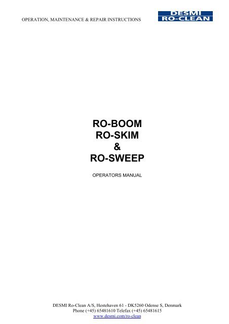
OPERATION, MAINTENANCE & REPAIR INSTRUCTIONS<strong>RO</strong>-<strong>BOOM</strong><strong>RO</strong>-<strong>SKIM</strong>&<strong>RO</strong>-<strong>SWEEP</strong>OPERATORS MANUALDESMI Ro-Clean A/S, Hestehaven 61 - DK5260 Odense S, DenmarkPhone (+45) 65481610 Telefax (+45) 65481615www.desmi.com/ro-clean
Contents1. Ro-Boom Page1.1 General description of Ro-Boom 21.2 Construction 21.3 Materials 21.4 Dimensions 31.5 Mechanical properties 41.6 General resistance 41.7 End connectors 41.8 Bracket 51.9 Eyelet 61.10 Ballast chain 61.11 Valve with cap 62. TOWING EQUIPMENT2.1 Towing equipment 72.2 Tow bars 82.3 Bridle 82.4 Tow rope 83. ACCESSORIES3.1 Winder 93.2 Tidal compensators 113.3 Ro-Skim 123.4 Ro-Sweep 144. USE OF THE SYSTEM4.1 Mounting of towing equipment 174.2 Hose connections 184.3 Deployment of the boom 184.4 Assembly of two sections 204.5 Towing of boom 214.6 Anchoring of boom 224.7 Recovery of boom 234.8 Boom formations 254.9 Weak link 284.9 Checking the system 284.10 Transport and storage 294.11 Forces 305. REPAIR5.1 Small repairs 315.2.1 Repair of leaky chamber 325.2.2 Repair of hole 335.2.3 Repair of cut 345.2.4 Repair of separated fabric layers 355.3 Repair of torn out eyelet 375.4 Repair of torn of hinge connector 395.5 Repair of defective or loose valve 435.6 Repair of broken fibre glass rod 462
1. <strong>RO</strong>-<strong>BOOM</strong>1.1 GENERAL DESCRIPTION OF <strong>RO</strong>-<strong>BOOM</strong>Ro-Boom is the toughest inflatable boom in the world. It is moulded in a composite of DuPont Hypalon® and Neoprene rubber and reinforced with two plies of polyester fabric.The air chambers are formed in a unique vulcanization process – there are neither seams norjoints that may leek or fail. Valve caps are smooth and protected by the valve seat.The Ro-Boom is rapidly filled using a high capacity air blower, and once deployed the boomwill remain inflated and afloat for month or even years. Mariners will recognize the value andintegrity of individual floatation compartments that are not linked.Ro-Boom will withstand the effects of sun, sea and oils. Attachments, such as eyelets andbrackets, are made from stainless steel.Ro-Boom can be supplied with a variety of section connectors. Ro-Boom lies completely flatwhen deflated allowing for easy cleaning and storage. A full range of reels, containers andmultipurpose power packs are available.1.2 CONSTRUCTIONThe boom is equipped with inflatable buoyancy chambers with separate air valves whichmean that in case of puncture only one chamber will lose air. Due to the rigidity and totalbuoyancy of the boom puncture of one chamber will not affect the function of the boom.Between the chambers the boom has a fibre glass rod. The rod is mounted in a ductcrosswise of the longitudinal direction of the boom between the two plies of fabric. The duct isin both ends closed by riveted brackets of stainless steel.The lower edge of the skirt is equipped with eyelets of stainless steel which are placedsymmetrically around the rods. These eyelets are used for mounting the ballast chain. Thelover part of the skirt is reinforced with a third layer of fabric vulcanized into the fabric on Ro-Boom 1500-3500.End connectors are mounted to the boom and ballast chain at the ends of each section. Thisenables easy assembly to either tow bar, further sections of boom or to carriages of tidalcompensator rails. The boom is black and standard marked with yellow stripes.1.3 MATERIALSThe boom is made from synthetic, oil and weather resistant rubber and has two inner plies ofpolyester/polyamide reinforcement fabric embedded in Du Pont Neoprene rubber. Thesurface cover is made from Du Pont Hypalon, chosen due to its optimum resistance to allkinds of weathering and UV light. All attachments, such as eyelets and reinforcementbrackets are made from stainless steel except the ASTM connectors which are made frommarine grade aluminium.3
The boom is resistant to sun, seawater and oil. The smooth, plane parallel surface of thedeflated boom makes cleaning after use easy (several types of oil do not stick to the boom atall). Cleaning can - when necessary – take place with solvent, high-pressure water ormechanically with scrapers.1.4 DIMENSIONSRo-Boom 1100-3500Ro-Boom 600-1000A : Boom width (deflated)B : Chamber section lengthC : Buoyancy chamber lengthD : FreeboardE : DraughtØ : Air chamber diameter1 : ASTM or Hinge type Connector2 : Valve3 : Bracket4 : Glass fibre strut5 : Chain6 : Eyelet7 : Handling string (only on RB 600-1000)Standard dimensionsRo-Boom-Unit 600 1000 1100 1300 1500 1800 2000 2200 3500A: Boom Width (Height) rolled up m 0,60 1,00 1,10 1,30 1,50 1,8 2,00 2,20 3,50Operational height inflated m 0,51 0,79 0,92 1,10 1,20 1,50 1,70 1,78 2,80B: Chamber section length m 2,13 3,13 3,13 3,3 4,9 4,9 4,9 6,48 7,0C: Buoyancy chamber length m 2,00 3,00 3,00 3,00 4,50 4,50 4,50 5,68 6,00D: Freeboard m 0,20 0,36 0,36 0,44 0,50 0,60 0,60 0,83 1,30E: Draught m 0,30 0,43 0,56 0,66 0,70 0,90 1,10 0,95 1,50Ø: Boom operational width m 0,18 - 0,38 0,38 - - 0,55 - -Standard section lengths m 15,25,50 25,50,100 50-300 (50 metre interval) 200Ballast chain mm 7 7 10 10 13 13 13 13 20Standard connector Hinge/ASTM A A A A A / H A / H H H HVolume of buoyancy chamber ltr 50 230 230 280 660 900 915 2100 5800Data are subject to be changed without notice4
1.5 MECHANICAL P<strong>RO</strong>PERTIESMechanical propertiesRo-Boom-Unit 600 1000 1100 1300 1500 1800 2000 2200 3500Weight per metre incl. chain Kg 4,0 5,4 7,0 8,0 10,5 12,5 13,5 15,5 35Buoyancy to weight ratio 7:1 11:1 10:1 14:1 17:1 18:1 20:1 22:1 23:1Tensile strength chain kN 50 50 90 90 200 200 200 200 400Tensile strength fabric (ISO 283) N/mm 250 250 250 250 315 315 315 315 400Tear resistance of eyelets kN 2 2 7 7 14 14 14 17 40Weir resistance of surface mm 3 150 (DIN 53516)Max. pressure in buoyancy ch. kPA 15 15 15 15 15 15 15 15 10Burst pressure of buoyancy ch. kPA 100 100 100 100 80 70 70 100 40Operational temperature -20 ºC to 70 ºCStorage temperature -40 ºC to 70 ºCElongation at a load of 80 N/mm % 4 4 4 4 4 4 4 4Efficient in waves up to m 2 2 2 3 3,5 3,5-4 4 4,5 6Stable in current up to Knots 3 3 3 3 3 3 3 3 3Deployment time 200 m Min 9 9 9 12 12 12 12 12 20Maximum in-line towing speed Knots 10 10 10 10 10 10 10 10 10Data are subject to be changed without notice1.6 GENERAL RESISTANCEResistance to oil (ASTM D 471): ASTM Oil No. 3 swell vol.
The ASTM connectors are mounted on the boom by means of stainless steel bolts. Foranchoring purposes they are mounted with an eye nut at the top and bottom.Lock pins for ASTM connectorASTM Connector. 1. Boom, 2. Back bar, 3. Stainless steelbolt, 4. ASTM Connector, 5. Hole for lock pin / boltHINGE type connectors are manufactured from stainless steel and mounted on the boomwith stainless steel pop rivets. For connection of one hinge connector to another, to a tow baror to the carriage of a tidal compensator a stainless steel rod is used.Ro-Boom 600 with Hinge connector and ballast chainHinge connector1.8 BRACKETStainless steel brackets are mounted above andbelow each glass fibre strut between thebuoyancy chambers. The hole in the bracket isconvenient to use for handling of the boom andfixing of lights, etc. Lifting in the brackets bymeans of crane or other machinery must beavoided as this may damage the Ro-Boom.Bracket on bottom of Ro-Boom 600Ballast chain mounted to eyelet on Ro-boom 1300by means of two chain links and shackleBracket on top of Ro-Boom 6006
1.9 EYELETThe lower edge of the skirt is equipped with eyelets of stainless steel which are placedsymmetrically around the rods by means of stainless steel pop rivets. These eyelets are usedfor mounting the ballast chain. On Ro-Boom 1500-3500 the area in which the eyelets areplaced is reinforced with a third layer of fabric vulcanised into the skirt.On Ro-boom 600-1000 the ballast chain is fixed direct to the eyelet with a shackle. On largersized booms two chain links are placed between the ballast chain and the shackle.1.10 BALLAST CHAINThe ballast chain is a hot galvanized high-alloy chain, which is mounted with stainless steelshackles equally spaced along the length of the chain. Chain connector links are mounted inboth ends of the chain. In these are mounted shackles meant for fixing to the tow bars orconnecting further lengths of chain.Ballast chain fixed to Hinge type tow bar.Ballast chain mounted to eyelet onRo-boom 600 with a shackle1.11 VALVE WITH CAPThe valve seats made from polyamide and moulded in rubber are vulcanized to eachbuoyancy chamber in such a way that the wall of the chamber forms a flap valve. This flapvalve temporarily shuts off the injected air when removing the filling probe. The valve coverwith rubber gasket is used for final sealing of the chamber.Removing the valve coverValve cover with rubber gasket7
2. TOWING EQUIPMENT2.1 TOWING EQUIPMENTTowing equipment for Ro-Boom 2000Towing equipment for Ro-Boom 15001: Tow Bar, 2: Shackle, 3: Bridle, 4: Tow rope, 5: Buoy8
2.2 TOW BARSRo-Boom can be delivered with two types of tow bars, the ASTM or the Hinge tow bar.The ASTM tow bar is an ASTM quick connector manufactured from aluminium profile. Ateach end are drilled two holes for mounting of the bridle.ASTM tow bar on Ro-Boom 1300The Hinge type tow bar is manufactured from heavy, threaded pipe, sealed at both ends bymeans of end covers with eyelets for mounting of chain, handling, etc. Along one side of thebar, tube stubs are mounted matching the hinge connectors of the boom. On the other side ofthe bar, heavy eyelets are welded to connect the bridle. The bar is hot dip galvanized.Hinge type tow bar for Ro-Boom 600 Hinge type tow bar for Ro-Boom 13002.3 BRIDLEThe bridle, consisting of polypropylene prongs with thimbles, is assembled with a ring at oneend.2.4 TOW <strong>RO</strong>PEThe tow rope is a polypropylene rope with spliced eyelets in one end and thimble in the other.The eyelet with the thimble has a class 1 shackle and is shackled to the oval ring of thebridle. The opposite end is shackled to a buoy by means of a shackle.9
3. ACCESSORIES3.1 WINDERThe Ro-Boom is typically delivered on a winder. The winder frame is used for storage,transportation and handling of the Ro-Boom. Various types of winders, tailor made for eachRo-Boom size and client specifications, are available.Containerised winderWinder frame for storage and hand crankedhandling of 100 metre Ro-Boom 1000Winder frame with hydraulic motor for storageand handling of Ro-Boom 1300Winder frame with hydraulic motor forstorage and handling of 200 m Ro-Boom1300Standard winder construction:The standard winder frame is manufactured from specially designed steel and standardprofiles.Two frames with bearing housings for a shaft are mounted on the bottom frame. On the shafta drum with end flanges is mounted. On one end of the shaft a sprocket wheel is mountedbetween the drum and the bearing housing. To rotate the drum a gearbox, with hydraulicmotor, is mounted on a bracket plate on the bottom frame. The rotating power to the drum is10
transferred by a roller chain. On hand cranked winders the gear box with crank is placed onthe side of the bearing frame.In order to secure the boom to the drum before winding, the drum is on each side equippedwith two eyes to which the two reeling wires are shackled.The bottom of the winder frame is equipped with two ISO forklift channels and in the cornersthere are four lifting brackets for strops for lifting by crane. The corners may have ISO cornerfittings suitable for fixing to a flat rack by ISO Twist locks.Lashing points are provided on the bearing frames by transverse pipes situated under thebearing base plate.Each winder may be delivered with a tarpaulin, which is mounted with rubber strops providedwith steel hooks.Surface treatment:The standard winder is abrasive-blasted to Sa 2½. After blasting, a coat of 40 microns ofHempel’s Hempadur Zinc 1536 has been applied. On top of the primer follows 100 micronsHempadur Hi-Build 4520. The finishing coat consists of 50 microns Hempathane Topcoat5521.Other surface treatment may be applied on request.11
3.2 TIDAL COMPENSATORSVarious types of tidal compensators are developed for Ro-Boom. The standard tidalcompensator set consists of:- two mounting brackets for fixing slide rail/pole to harbour wall or pole- slide rail or pole- slide bar mounted on the Ro-Boom end connector and sliding along the sliderail/pole with 2-3 slide brackets- sealing flaps for sealing area around tidal compensatorRo-Boom mounted on tidal compensators in Gravelines, France.Tidal compensator consisting of hinge bar mounted on floating slide bracket sliding up anddown the mooring post.Tidal compensator consisting of ASTM bar, with sealing flaps, sliding on slide pole by meansof 3 slide brackets.12
3.3 <strong>RO</strong>-<strong>SKIM</strong>The Ro-skim is constructed fromboom material, aluminiumplates/profiles and connectors forconnecting to the Ro-boom. In theboom material is cut an openingthrough which the oil can flow intoa funnel via an adjustable weir lip.Under the funnel is placed aDESMI DOP160/250Dual pump todischarge oil from the funnel.Buoyancy chambers are on some Ro-skim models build in to the boom wall and for additionalbuoyancy fenders are placed under the funnel. The height of the fenders can manually beadjusted by a string to suit the conditions at the recovery site.WEIR LIP and FUNNELIn the boom wall, a square hole is cut. Behind this hole the funnel is clamped on to the twoboom connectors. In between the boom wall and the funnel is mounted a hydraulicallyadjustable weir lip. On top of the weir lip are welded six pins which provide a rough grill toprevent big pieces of debris to enter the funnel. At the top of the funnel is a hinged lid whichgives access to cleaning.DIMENSIONS : Ro-Skim 2000 L x W x H: 2000 x 1100 x 650 mmRo-Skim 1500 L x W x H: 1500 x 1100 x 650 mmWeight: Ro-Skim 2000: Approximately 200kg incl. DOP 250 Dual pumpRo-Skim 1500: Approximately 175kg incl. DOP 250 Dual pump13
ASSEMBLY of <strong>BOOM</strong> SECTIONS (<strong>SWEEP</strong>) and <strong>RO</strong>-<strong>SKIM</strong>As the connector of the boom, of which the <strong>RO</strong>-<strong>SKIM</strong> has to be a part, comes approx. 5metres away from the winder, the boom is stopped off, and the <strong>RO</strong>-<strong>SKIM</strong> can now be pushedin to position and connected to the first Ro-Boom section, Refer section 4 “Use of thesystem".Before pushing the Ro-Skim into the water the ends of the hose set are connected to theconnectors on the pump/Ro-skim. The other ends of the hose set is kept onboard or droppedinto the water with a buoy for easy pick up later when oil pumping starts.The two connectors at the end of the first section and the beginning of the <strong>RO</strong>-<strong>SKIM</strong> sectionare assembled and the chains of the first section and the <strong>RO</strong>-<strong>SKIM</strong> section are assembled bytheir respective shackles. Thereafter the second Ro-boom section is assembled to the Roskim.<strong>RO</strong>-<strong>SKIM</strong> PUMPIn case the pump, for some reason, gets clogged up it is possible to reverse the hydraulicflow and thereby the rotation of the pump. The reverse flow is restricted to avoid reversingthe pump with full speed since the lay flat hose will collapse, and in the worst case theoffloading hose will turn inside out into the pump. The hydraulic drain hose has to have freeflow back into the oil tank to avoid spoiling the oil motor sealing.14
3.4 <strong>RO</strong>-<strong>SWEEP</strong>The <strong>RO</strong>-<strong>SWEEP</strong> is based on the Ro-Boom range ofoil containment booms with an outrigger with a floatmanufactured in robust galvanized steel or aluminium.<strong>RO</strong>-<strong>SWEEP</strong> can be supplied in any size of Ro-Boomwith different sweep widths to suit the vessel. The jibis available fitted with a floatation unit, alternatively thecrane of the vessel can support the jib. SpecializedRo-Boom Reels are available to store, deploy andrecover the boom wings.15
JIBThe jib is made of 1 or more sections of galvanisedsteel trellis mast or aluminium pipe.The outer jib section is furnished with eye plates forconnection of forestay, block with tow ropes for oilboom and top hanger wire for lifting of the jib bycrane.GOOSE NECK FITTINGThe jib is attached to the vessel by means of a hotgalvanized steel base plate with kingpin and gooseneck fitting allowing the jib to move both horizontallyand vertically.The goose neck fitting can be attached to the shipeither by welding or bolting.PONTOONAt the outer end of the jib a marine grade aluminium pontoon may be mounted. The pontoonis connected to the jib providing the necessary buoyancy when in use. When not in use thepontoon is removed and stored on the deck or any appropriate place.DEPLOYMENT OF SIDE <strong>SWEEP</strong>This is a general description of deployment of jib with side sweep. Before deploying the jibover the side of the vessel and fixing it to the goose neck, an aft and forward stay areshackled to the outer end of the jib, near the float. At the same time a pulley block is shackledto the outer end of the jib for pulling the boom in figuration.A fairly long tow rope of up to 20 mm diameter is threaded through the pulley block. The towrope has to be long enough, so that one end can reach a winch, preferably on the foredeck(anchor winch). The other end of the tow rope has to reach the deck, from where the sweepis deployed. Another tow rope is prepared so that it runs along ship from the winch on theforedeck, under the jib and its stays to the deck from where the sweep is deployed.When the first end of the boom side sweep comes on to the deck, a tow bar with bridle ismounted and the end of the tow rope from the pulley at the end of the jib is tied to the bridle.As the boom side sweep is deployed it is gradually pulled towards the outer end of the jib bymeans of the winch on the fore deck (or by hand). The tow bridle is pulled right up to thepulley of the jib (please note that tow bridles for side sweeps are usually shorter than boomtowing bridles).16
When the last end of the side sweep comes on to the deck, it is stopped off, and a tow set,with asymmetric bridle, is mounted and the remaining tow rope running along ship to theforedeck.Before releasing this “last” end of the side sweep from the stopper, it has to be ascertainedthat the tow rope is free to go into the sea with the boom, and that the opposite end of thetow rope is secured on the foredeck. Now the stopper can be released and the sweepentered into the sea, while it is being winched forward along the side of the vessel.Make sure that the side sweep is pulled sufficiently forward so that it cannot be pulled into thepropeller of the vessel, in case the shape of the vessel is unfavourable and suction frompropellers are excessive.17
4. USE OF THE SYSTEM4.1 MOUNTING OF TOWING EQUIPMENTThe towing equipment for the boom is mounted by winding off the boom so that the firstASTM/Hinge connector can be placed on deck or quay. The connection is easy with the twoparts of connector profiles. The ASTM connection is made safe by the lock pins fitted to theconnectors by the pin chain or bolts for long term deployment.The Hinge connection is made safe by locking the position of the steel rod between the hingeconnectors by means of a snap hook. The chain is secured to the tow bar with shackle andseizing wire.The bridle is mounted to the tow bar by shackles. Shackles have to be tightened with aspanner and even seized with seizing wire if in use for a prolonged period.18
Having mounted a buoy in the soft eye of the tow rope, the latter is thrown into the water, theopposite end of the towrope with thimble is shackled to the oval ring of the bridle. Ifdeployment is made from deck, the ship should preferably stand in such a way that currentand wind take buoy and tow rope away from the ship to facilitate the deployment and toprevent tow rope and bridle from fouling the propeller.4.2 HOSE CONNECTIONSThe air filling hose is connected to the pressure sideof the air blower. NOTE: The hoses for inflation anddeflation of the buoyancy chambers must NOT comein contact with water, sand or the like when mountedon the suction side as the blower will then bedamaged. Hoses must always be in hand whenblower is in operation. The outer gasket is dismantledduring emptying of the air chamber.4.3 DEPLOYMENT OF THE <strong>BOOM</strong>The easiest way to deploy a boom is from a boat. This is because the boat can be positionedwith its nose into the current. The boom will stream off the stern in a straight line. It is stronglyrecommended that the trailing end is first picked up once the whole length is deployed. If it isnecessary to do so beforehand, only a small boat should be used. This is for safety reasonsto prevent the boom being pulled sideways across the deck. In restricted spaces thedeploying boat can sail in a large circle at 1 to 1.5 knots, the forward motion helps ease theboom off the deck and into the water.Deploying from a fixed jetty or quay can be a little more difficult to control. The boomdeployment site should be chosen carefully to make use of currents. Deployment, and moreimportantly recovery, across the current can create considerable difficulties as the angle ofthe boom relative to the reel must be as little as possible. Anything that helps to reduce thedeflection from the ideal line should be utilised.All oil booms will only contain oil in a 'U' configuration at relatively low tow speeds. Beyondthis eddies created by the water passing under the boom will start to induce the oil tosubmerge and pass underneath.Ro-Boom can be towed in a straight line (i.e. when proceeding to spill location) at speeds upto 10 knots. Care should be taken to ensure sufficient length of tow line to avoid boom endlifting out of the water. Ro-Boom can be towed in 'U' or 'J' formation at speeds up to 3 knots.In the event excessive forces are applied to the boom, the towing line provided is designed topart to protect the boom.Ro-Boom is of very robust construction and will withstand dragging over concrete etc.However a roller at the quay's edge will ease operations and sharp objects in the deploymentpath should be avoided.19
Before deploying the boom ensure that you have:- A clear working space to allow inflation of two air chambers simultaneously. Deploymentsurface should be free of protrusions and sharp obstacles.- Secure anchoring for boom reel -you may weld the reel to the deck or secure with bolts orchains/wires.- Free access to water.- Towing boat(s).- Communication from deck to wheelhouse.It is essential that all those involved are briefed in the sequence of events. A team leadershould be appointed who will be responsible for:- Controlling speed of deployment.- Co-ordinating towing vessel(s).- Looking after safety of operators.This person holds the key to a safe and successful operation. Operators and Captain(s)should communicate with him only.SafetyIt is essential that safety of operators is given first consideration. Life vests, hard hats andsafety shoes should be worn at all times. The winder must be properly secured to the deck orquay before starting deployment.Deployment Hints- Check fuels/lubricants in power pack, keep an eye on hydraulic oil levels.- Position the power pack so the operator can see the whole working area.- Treat the deployment like a production line. With practice filling of chambers and placingcaps becomes a smooth continuous operation.- Place the yellow valve caps in a bucket of water with some detergent. This helps therubber gasket slide against the valve face.- Ensure the chain shackle is attached to the tow bar or to the chain of the next boomsection. Secure the shackle pins with seizing wire if rough sea conditions prevail.- The buoyancy chambers are inflated by means of the air probes on the air filling hose. Thechambers are inflated until they reach full shape. A valve cap is held ready and mounted inthe valve. Until the first few air chambers of the boom have been launched two of theoperators must jointly pull the boom over the edge of the ship or quay into the water.- When connecting sections together lay the hinge plates flat on the deck before trying toinsert pin. Always use the boom stopper wire to prevent the boom being pulled across thedeck whilst this operation is being conducted. Connecting pins should be secured with atie to the hinge connector.- The strops of the towing bridle are different lengths. They are colour-coded and should beattached to the tow bar in the right sequence, avoiding twists or tangles.- The last portion of boom to come off the reel will be attached by means of two wire strops.Secure boom with stopper wire prior to disconnecting boom from reel. Then attach towbar or additional boom section.NOTE: When boom sections with ASTM connectors are stored on the winder the ASTMconnectors are secured with bolts and not with lock pin. This is to avoid the lock pins fromdamaging the Ro-boom. If the bolts are removed during deployment they will have to bereplaced when the boom sections are recovered onto the winder.20
4.4 ASSEMBLY OF TWO SECTIONSAssembly of two or more sections can either be made by placing two winders behind eachother or by exchanging the empty winder for a full one.In the first case- the connector at the end of the deployed section is fastened by an auxiliary wire to its ownwinder- The hydraulic hoses are changed from the front winder to the one behind. Winding off ofthe second section take place over the first drum- The two connectors and chain ends at the end of the first section and the beginning of thesecond section are assembled.- Then the auxiliary wire is dismantled from the end of the first section and deployment ofthe next section can take place.21
Connection of boom to tow barConnection of two boom sectionsIn the other case, where hoisting equipment is available, the chain of the first section can befastened onboard or on the quay, and the empty winder can then be changed for a full one.The connectors and chain are assembled and deployment can continue. The advantage ofexchanging the winders is that more direct access to the second section is obtained and thatpulling the boom over the first drum is avoided.If more than two sections are to be deployed, it is recommended that the winder replacementmethod is adopted. However, up to four sections have been deployed by the “pull through”method.4.5 TOWING OF <strong>BOOM</strong>Towing of the boom in a straight line requires small power consumption and is advised inconnection with towing from deployment place to the place of use.With a view to towing in U-shape or encircling an oil slick, the first deployed tow rope isprovided with a buoy which can be easily picked up by an auxiliary vessel. The boom issymmetric and has as such no front or back side.22
4.6 ANCHORING OF <strong>BOOM</strong>The best way of anchoring the boom is to secure anchors to the tow rope, bridle or tow barwhich will distribute the forces on the boom in the best way.In order to connect an anchor to an ASTM connector between two sections, the nuts at thetop and bottom of the connector are replaced by eye nuts so that bridle and anchor rope canbe connected.End connector1 : Shackle2 : Bridle3 : Slip hook4 : Rope5 : Anchor buoy6 : Buoy7 : Tow rope for buoy8 : Anchor rope9 : Chain connection link10 : Anchor chain11 : AnchorAnchoring to the ballast chain of the boom is also possible. Here it must be remembered thatanchor points must be evenly distributed along the chain in order to distribute the load. Forspecial purpose anchoring, specially designed cross bars can be mounted between thebuoyancy chambers and connected to the anchors.Cross barEye nutBoomEye nut for bridleBoltRubber wear plateEye nutGlass fibre rodAluminiumU-Profile23
4.7 RECOVERY OF <strong>BOOM</strong>Recovery of Ro-Boom is a reversal of deployment. Firstly the auxiliary tow boat shouldrelease its tow line and allow the boom to drift line astern of the deployment vessel. Neverattempt to wind up the boom with the tow boat still attached! The deployment vessel maymaintain a slow forward speed to keep the boom directly astern and assist the recovery andre-winding operation.- Recovery of the boom is made by hauling in the tow rope and using the winder drum as acapstan. Ensure that the winder is properly secured.- Remember that recovery of the boom is started at the last deployed end with the floatationchambers turned towards the side where the sprocket wheel of the drum is placed. This isdone in order to secure that the valves of the floatation chambers are turning upwards andaway from the drum so that any possible remaining air is pressed out during the windingoperation.- When the tow bar and first end connector come to the winder frame the boom is fastenedby an auxiliary wire with chain hook or a rope, and the towing equipment is removed andreplaced by the connector/reeling wires.- Ro-Boom is deflated by placing air hose on suction side of blower. Do not wind up anychambers which are not completely empty as this may damage the chamber. Air probe willhold open non-return flap. Ensure once air chamber is evacuated non-return flap is notbent backwards.- Check that no remaining air is trapped in the buoyancy chamber. If air is trapped, it can bereleased by pressing the flap valve when the boom is reaching the winder drum.- Oil boom should be cleaned prior to storage utilising pressure washers or similar.- Spray rust inhibitor into air blower prior to storage.24
4.8 <strong>BOOM</strong> FORMATIONSThere are three possible boom formations depending on the number of vessels involved inthe formation:- Single vessel system deployed on one or both sides of the vessel.- Two vessel system, also called J-formation.- Three vessel system, also called U-formationSingle vessel formationSingle vessel formation Dual modeSingle vessels systems.The system normally consists of a Jib giving the fixed opening of the sweep system. Thelength of the Jib will normally be 6 – 15 meters and the boom length will normally be 3 timesthe length of the Jib, i.e. 18 – 45 meters.For keeping the Jib in the correct position tow lines are deployed from the outer end of the Jibto fore and aft of the vessel respectively.The end of the boom formation is normally called the “Apex”. The apex is where the oilconcentration is highest. This is where the skimmer should be placed to ensure that it is ableto collect the maximum amount of oil.Two vessel system.In a J-formation the opening of the boom system can be upto 200 meters. The maximum total boom length used isapprox. 500 meters.The procedure used when creating the J-formation is todeploy the boom from the main (lower) vessel, which willnormally be the larger of the two vessels being used. Oncethe entire boom length is deployed, the assisting (upper)vessel picks up the boom and proceeds to a position in frontof the main vessel to create the required J-formation.It is important to emphasize that it is the master on the mainvessel who is in charge of the operation. This means that themaster of the main vessel is also in charge of advising themaster of the assisting vessel as to where he should bepositioned.Two vessel J-formationWhen the assisting vessel is in position, the Apex is formed.The skimmer will then be deployed at the apex of the boom formation. As the hoses used foroperating the skimmer will normally not exceed 40 meters, it is important to ensure that theApex is fairly close to the main vessel (20 – 30 meters). Sometimes tow lines are connectedfrom the boom to the vessel close to the apex in order to keep an optimum shape of theboom formation. The tow ropes should be connected to the boom when it has beendeployed.25
This formation is by far the most complicated formation to create as the position of theassisting vessel is very important. If the assisting vessel is too high compared to the mainvessel, the oil will be guided to the side of the vessel. If the assisting vessel is too lowcompared to the main vessel the apex is moving downwards and the skimmer will not be incontact with the oil.Three vessel system.U-FormationOpen U-FormationWhen three vessels are involved in one boom formation it is called a U-formation. In aconventional U-formation the third vessel is placed at the apex of the system and a skimmeris deployed at the apex of the formation. This will normally require the third vessel to have thecapability to sail sideways.A variant of the U-formation is the Open U-formation where the apex is open and a funnelmade of boom guides the concentrated oil into a Single Vessel Sweep formation.The maximum length of boom which should be used in a U-formation is 800 meters and theopening of the system can be up to 350 meters.As the two vessels keeping the formation are side by side it is fairly easy to keep the correctshape of the formation. The vessel positioned at the apex will always be the main vesselgiving commands to the two other vessels.26
Deployment of open U-configurationTo form an open U-Configuration following is needed:- 2 Ro-Boom sections- 2 cross bars- 4 shackles- 4 x 8m wires to connect the 2 cross bars and 2 towbars at the end of the boom sections- The first 100m section is deployed until only the last twoair chambers are on deck. The tow bar is mounted tothe end of the boom and the ballast chain connectedand secured.- In the top and bottom of the tow bar the two 8 m wiresare mounted.- Between the third and second last chamber the firstcross bar is mounted around the fibre glass rod. Theends of the two 8 m wires are mounted to the eye boltson top and button of the cross bar.- The second 100 m section is deployed until only thelast two chambers are on deck. The tow bar is mountedto the end of the boom and the ballast chain connectedand secured.- The ends of the wires connected to the tow bar on thefirst section are mounted in the top and bottom of thetow bar of the second section.- Between the third and second last chamber the secondcross bar is mounted around the fibre glass rod. Theends of the wires connected to the cross bar of the firstboom section are mounted to the eye bolts on top andbutton of the second cross bar.Boom section1 - 2CrossbarsThe two boom sections can now be deployed.Cross barEye nutBoomEye nutBoltRubber wear plateEye nutGlass fibre rodAluminiumU-Profile27
4.9 WEAK LINKAs it can be difficult to control the forces on a system and avoid these forces from exceedingthe breaking strength in the system, it is vital to insert a “Weak Link”.In any Ro-Boom system the towing line has been calculated to have a lower breakingstrength than the boom.The philosophy is that it is much cheaper and simpler to replace a tow line than a boom. Ifthe tow line is replaced make sure it is not replaced with a tow-line with higher breakingstrength than the original.4.10 CHECKING THE SYSTEMAfter each deployment the boom is to be checked. If the boom has been used in connectionwith oil pollution, all equipment which is smeared in oil should either be cleaned with suitablecleaning equipment or transported to a special washing place with an oil separator. Theequipment can be washed down by means of a high-pressure cleaner with possible use of oilsolvents. However, do take care that these solvents do not prevent the oil separator fromfunctioning.For cleaning the boom with chemicals, the following guidelines can be given:- The oil boom is made from a material that normally makes it resistant to detergents onpetro-chemical basis.- Detergents with low contents of aromatics will be the most lenient for intensive treatment.- Detergents based on N-paraffin’s are recommended due to their environmental properties.The following type of detergent is recommended.Exxsol® D 80Chemex Products A/STel. +45-74629192Detergents containing methylene chloride, trichloroethylene, ketones, aldehydes or estersmust not be used. The boom itself repels many types of oil, but in case of heavy oiladherence, non-metallic scrapers can be used and/or high-pressure cleaning.Handling of the boom is easier if an empty winder is available at the washing place so thatthe boom can be wound up as the cleaning is progressing. However, it is also possible to foldthe boom manually and then wind it back on the winder.A special oil boom cleaning unit, <strong>RO</strong>-WASH, has been developed by DESMI Ro-Clean.Please enquire.28
Please check that the chain and the sprocket wheel of the winder are well greased with ballbearing grease after rinsing. Check that all thread holes of shackles, etc. are well greasedwith ball bearing grease.4.11 TRANSPORT AND STORAGEThe system is easily transported and stored on a winder with channels for fork lift at thebottom as well as bridles for lifting by crane.The outside the legs of the winder frames areprovided with a welded edge which makes itpossible to pull the frames on the deck withcapstan or winch. The winder frames mustalways be lashed down to the deck to preventthem from slipping, during operation.The boom can be stored for many years withoutdeterioration however there are factors that willprolong life of boom:- Store boom clean and devoid from oil.- Store boom correctly wound on reel withoutchain overlapping fabric- Store boom out of sunlight.- Limit temperature to -20ºC to +60ºC.The boom may be stored outdoors as well as indoors. In case of outdoor storage, pleasecheck that scratches on the surface of the equipment are repaired to prevent rust.Take care that the boom and nylon tow ropes are not exposed to unnecessary sunlightduring storage.29
4.12 FORCESCurrents*To estimate the approximate force Fc(kg) exerted on a boom with a sub-surfacearea As (m²) by a current with velocity Vc(knots) the following formula can be used:Fc = 26 x As x Vc²Thus, the force acting on a 100 m lengthof boom with a 0.6 m skirt placed at rightangles to a 0.5 knot water flow would beFc = 26 x (0.6 x 100) x (0.5)² = 390 kg(force)When a boom is towed, its velocitythrough the water should be entered as Vcin the above formula.It can be seen that doubling the currentvelocity or towing speed would entail afour-fold increase in load.Windage*The force (Fw) exerted by wind (Vw)directly on the freeboard (Af) of the boom,can also be considerable. A similarformula can be used to estimate windage:Fw = 26 x Af x (Vw/40)²For example, the force on a 100 metrelength of boom with a 0.5 metre freeboardin a 15 knot wind would be:Fw = 26 x (0,5 x 100) x (15/40)² = 183 kg(force)Combined Forces*In the above example the combined forces of current and wind would be 573 kg if they wereacting in the same direction on a rigid barrier. In fact booms are flexible and form a curve. Inaddition, the boom would be towed or moored at an angle to the flow. Both these factors leadto a reduction of the forces acting on the boom so that a considerable safety margin isincluded in the result of this calculation. Nevertheless, it provides a useful guide to themagnitude of such forces and can help in the selection of appropriate moorings or towingvessels.* By courtesy of the International Tankers Oil Pollution Federation30
5. REPAIR5.1 SMALL REPAIRSSmall repairs of the boom fabric can be made by means of a repair kit for cold vulcanizationof rubber (a repair set can be ordered from DESMI Ro-Clean, please enquire). Theprocedure is the same as when mending a bicycle puncture:- Degrease the patch and the damaged area- Raise the surface by sandpaper or rasp- Mix hardener with cement- Apply the mixture to the boom surface- Leave it to dry for ½-1 hour- Repeat the application and leave it to dry- Remove the protective film from the patch and apply the mixture- Leave it to dry until it is tacky- Press the two units together under as high pressure as possibleIn case of major repairs, e.g. when one or more buoyancy chambers have to be re-moved,please contact DESMI Ro-Clean who will decide whether repairs should be made by aspecialist at the place of storage or whether the boom should be shipped to the factory.If only one chamber has punctured the boom is still operational, i.e. the repair can wait till amore convenient time, if needed.31
5.2.1 REPAIR OF LEAKY CHAMBERMATERIALSRepair kit, repair patches, vulcanized rubber coated repair fabric, TIP TOP glue SC 4000 –Cold vulcanization cement (A) incl. Hardener (B), Dissolvent: Benzine, methylene chloride orthe like.The cement is delivered in sets, i.e. a bottle of hardener corresponds to a can of cement. Thewhole portion can be apportioned before mixing if only a little is needed, but care should betaken to use the correct proportions which are 1 part of B and 10 parts of A (scales). Aftermixing of A and B the cement should be used within 4 hours. During these 4 hours the canmust be kept closed when the mixture is not used, as otherwise the cement will become veryhard and unfit for use.The repair kit consists of a number ofpatches, similar to those used for mending ofautomobile tubes. The glue, however, has tobe purchased separately due to the fact thatit is considered as dangerous goods andtherefore must be sent according toregulations of such goods. These patchesare pre-treated and should be applied onlyonce.TOOLS- Disc. grinder- Grinding discs P50- Rubber hammer- Pressing roller- Brush (Ø30 m round and short bristles)- Knife / scissors- White oil chalkIf the buoyancy chamber has been cut, punctured, worn through or damaged in any otherway caused by outside conditions, the damage has to be fixed.Depending on the situation and the extent of the damage, the repair can either be madeimmediately on site or later when the damaged part has been brought to a workshop.However, should the situation require repair on site, the best solution will be to use the repairkit that is included in the standard tool box.32
5.2.2 Repair of hole1) Hole is recognized. 2) Hole and area nearby is grinded.3) Adequate Tip Top patch is found. 4) Cement is brushed onto the grinded area.5) Cement has to dry. 6) Patch is placed and rolled on with a roller7) Repair of the hole is finished.33
5.2.3 Repair of cutIf the damage is large the most suitable materials for patching will be vulcanized rubber coveredrepair fabric and cement TIP TOP SC 4000 as solution. The procedure is as follows:1) Cut a patch of repair fabric in a suitable size. 2) min. 100 mm to the damage.3) Degrease and raise the patch and the damaged area. The raising of the surfaces is mostefficiently done with a disc grinder on which a rubber back plate and a grinding roundel of gradeP50 have been mounted.4) Cement SC 4000 (J2268 A+B) can now be applied onthe surfaces. The cement is applied to both surfaces thathave to be joined. Use a shorthaired and round paintbrush and apply the cement in circular movements sothat the cement is almost rubbed into the fabric. Try toobtain an even and thin covering layer.After application the cement has to dry for ½-1 hour,depending on the ambient temperature, air humidity, etc.The cement must be completely dry.Repeat the above application and leave it to dry. Thecement must still seem adhesive (2-5 minutes dryingtime).5) The two units are then pressed together under as highpressure as possible. A rubber hammer is used forstraightening of possible blisters, and care is taken thatthe patch is affixed to the fabric everywhere. Rolling ofthe patch with a pressing roller would be ideal forobtaining optimal adhesive strength.The vulcanized patch will now have such an adhesivestrength that the chamber can be carefully inflated.34
5.2.4 Repair of separated fabric layersSeparation between the fabric layers of the over splash fin of the boom resulting in punctureof the chamber will normally be seen only if the boom has been mistreated or overloaded.This may happen if high pressure air is used (more that 0.5 bar) or if the air chamber issqueezed between e.g. the sides of two ships. If only one chamber has punctured the boomis still operational, i.e. the repair can wait till a more convenient time, if needed.MATERIALS and TOOLS (Refer section 8.1)Materials:- TIP TOP glue SC 4000: Cold vulcanization cement (A) incl. Hardener (B)- Dissolvent: Benzine, methylene chloride or the like.Tools:- Disc grinder- Grinding discs P50- Rubber hammer- Pressing roller- Brush (1” round and short bristles)- Screw clamps and boards, 20 mm thick- Curved knife- Coarse file1. If caused by overpressure in the chamber theseparation between the fabric layers of the finwill look as shown in drawing no. 1. However,making the repair from this point is ratherawkward. Therefore, the separation is widenedby means of a sharp knife, refer photo 1.Drawing 1Photo 1This results in an opening as shown in drawingNo. 2.Drawing 22. The area is washed off in benzine, methylenechloride or other suitable dissolvent.Photo 23. Both surfaces for the gluing must be raised with a grinder. This is a difficult process, butby putting plates upright in the opening, refer photo no. 3, it is possible to grind thecentral part of the fabric layers. The extreme parts of the opening where the fabric layersare still sticking together shall be finished by hand, either with a piece of sandpaper or35
with a coarse file as shown in photo No. 2. When the whole area has been raised cementcan be applied to the two surfaces, refer photo no. 3.Photo 3. Photo 4.The cement is delivered in sets, i.e. a bottle of hardener corresponds to a can of cement.The whole portion can be apportioned before mixing if only a little is needed, but careshould be taken to use the correct proportions which are 1 part of B and 10 parts of A(scales). After mixing of A and B the cement should be used within 4 hours. During these4 hours the can must be kept closed when the mixture is not used, as otherwise thecement will become very hard and unfit for use.4. The cement is applied to both surfaces which have to be joined. Use a shorthaired andround paint-brush and apply the cement in circular movements so that the cement isalmost rubbed into the fabric. Try to obtain an even and thin covering layer. Afterapplication the cement has to dry for ½-1 hour, depending on the ambient temperature,air humidity, etc. The cement must be completely dry.5. Repeat the application process and let it dry.6. Apply a third time. This time the cement must seem adhesive (2-5 minutes drying time).When the two surfaces are ready to be joined at least two persons should be present, asthe correct placement of the surfaces requires much accuracy and precision so that therewill be no folds in the joint. When the surfaces have been correctly joined they arehammered with a rubber hammer to squeeze out any air.7. After this operation it is recommended to put the joint under pressure for 8-10 hours. Bymeans of screw clamps a couple of boards are pressed on to either side of the joint referphoto no. 4. Or, if screw clamps are not available, something heavy may be placed onthe top board (100-200 kg).After the repair of the boom we recommend to wait for at least 24 hours before deploying theboom again.When using the above method of cold vulcanization it will not be possible to obtain theoriginal amount of ply adhesion between the fabric layers, so it is recommended to mark onthe damaged air chamber that it should be treated carefully, i.e. hard inflation should beavoided.36
5.3 Repair of torn out eyeletMaterials:- Eyelet- Pop rivets for eyelet- Pop rivets for bracket- Vulcanized rubber coated repair fabric- Tip Top SC 4000 cold vulcanization cement A incl. hardener B- Dissolvent: Benzine, methylene chloride or the like.Tools:Disc grinderGrinding discs P50Rubber hammerBrush (l", round and short bristles)Pop riveting pistolØ4 mm drift punchHammerDrilling machine (5 mm drill)Hollow punch 022Screw clamps boardsAfter tearing out of an eyelet the fabric of the boomwill always be damaged and therefore the first stepwill be to repair the fabric. In case the eyelet is stillattached to the fabric it must be removed by drillingout the rivets.In order to obtain the original strength, the damagedarea must be reinforced by a layer of rubber coatedfabric on both sides. This fabric must exceed thenearest damaged point by at least 100 mm in size.The following method of repair must be used:Photo 11. First, the area is washed off in benzine, methylene chloride or other suitable dissolvent.2. Then the area is raised with sandpaper, either by hand or by means of a disc grinder,refer photo 2, on which rubber back plate and grinding roundel have been mounted (takecare not to damage the fabric during grinding).3. Upon completion of the grinding the units are ready for application of cement. It isessential not to smudge the ground areas. Preferably they should not be touched.The cement is delivered in sets, i.e. a bottle of hardener corresponds to a can of cement.The whole portion can be apportioned before mixing if only a little is needed, but careshould be taken to use the correct proportions which are 1 part of B and 10 parts of A(scales). After mixing of A and B the cement should be used within 4 hours. During these4 hours the can must be kept closed when the mixture is not used, as otherwise thecement will become very hard and unfit for use. It is advised to use scales for theapportioning.The cement is applied to both surfaces. Use a shorthaired and round paint-brush andapply the cement in circular movements so that the cement is almost rubbed into thefabric. Obtain an even and thin, covering layer.37
After the application, the cement is to dry for ½-1 hour, dependent on the ambienttemperature, air humidity, etc. The cement must be completely dry.4. Put on a second coat of cement and let it dry completely again.5. Put on cement for the third time. This time the cement must still seem adhesive (2-5min.of drying). The two units are then pressed together under as high a pressure as possible.A rubber hammer is used for straightening of possible blisters, and care is taken that thepatch is affixed to the fabric everywhere. Rolling of the patch with a pressing roller wouldbe ideal for obtaining optimum adhesive strength. Photo 3. Already after a few minutes,the vulcanized patch will have such an adhesive strength that the next eyelet can bemounted.Photo 2 Photo 3Photo 4 Photo 56. The eyelet consists of two identical halves which are riveted around the rubber part. Ifthere is a clear mark of the big eyelet hole in the boom, this is used to re-establish thehole with a hollow punch (16 mm), thus defining the exact position of the eyelet plates. Ifit is impossible to see the mark of the old hole, you have to mark it yourself according tothe sketch with dimensions.When the hole has been punched, an eyelet is placed above this and used as a templatefor the 7 rivet holes (5 mm drill). An eyelet is placed on the opposite side and seven rivetsare hammered in with a hollow drift punch. The riveting can now be effected, and it mustbe checked that all rivets are expanded on the back of the eyelet, refer photo 5.Before the boom is deployed again, we recommend waiting 24 hours after the repair work toachieve full strength of the cold vulcanized patch.38
5.4 Repair of torn of hinge connectorMATERIALS and TOOLS (Refer section 8.1)Materials:- Hinge connector- Pop rivet Ø5 x 19- Pop rivet Ø5 x 16- SC 4000 Cold vulcanization cement A incl. hardener B- Dissolvent Benzine, methylene chloride or the like.Tools:Drilling machine (5 mm drill)Rubber hammerHollow punch (16 mm)Knife / scissorsTape 75 mmHacksawHollow drift punch (hollow for rivets)Ø4mm drift punchHammerPop riveting pistolBrush (1”, round and short bristles)Screw clampsGrinding discs (P50)Pressing rollerSquareDisc grinderIf a hinge connector is torn off or damaged in such way that replacement is necessary, awhole air chamber will normally have to be removed as there will not be sufficient space toremount the connector in front of the first chamber.The following method of repair must be used:1. Remove the fibre glass rod located between the first and the second air chamber bydemounting the bracket plates which close the ends of the fibre glass channel. Then pullout the rod of the opened fibre glass channel. In order to loosen the rod from the walls ofthe channel you may need to beat slightly with a rubber hammer on one end of the rodthrough the wall of the channel. Take care not to damage the fabric of the channel wallwhen doing this.2. After the fibre glass rod has been removed, the boom must be shortened in the correctdistance from air chamber No. 2. The distance from the closest point of the air chamberto the cutting line is for all Ro-Boom models 660 mm, refer drawing 1.3. An area of the whole width of the boom from thecutting line and 440 mm inwards must beprepared for vulcanization. Wash the area withbenzine, methylene chloride or other suitabledissolvent. Raise the surface with a disc grinder(rubber back plate with P50 grade sandpaper).See to it that the fabric is not damaged and do notsmudge the prepared area. Photo 1.4. Now mark the area on which should be appliedcement. 440 mm from the cut end mark a crossPhoto 1.line over the boom (use silver ball pen or waxcrayon). 220 mm from the cut end you put crosswise a piece of 75 mm tape, in order notto apply cement in this area, refer drawing 1.39
220 mmVulcanized areaTolerance +/- 5mm660mm440mm183mm75mm tapeOld channelDrawing no. 15. The end of the boom is now ready for application of cement SC-4000. The cement isdelivered in sets, i.e. a bottle of hardener corresponds to a can of cement. The wholeportion can be apportioned before mixing if only a little is needed, but care should betaken to use the correct proportions which are 1 part of B and 10 parts of A (scales). Aftermixing of A and B the cement should be used within 4 hours. During these 4 hours thecan must be kept closed when the mixture is not used, as otherwise the cement willbecome very hard and unfit for use. It is advised to use scales for the apportioning.The cement is applied to both surfaces. Use a shorthaired and round paint-brush andapply the cement in circular movements so that the cement is almost rubbed into thefabric. Obtain an even and thin, covering layer of cement. After the application, let the40
cement dry for ½ - 1 hour (dependent on the ambient temperature, air humidity, etc.). Letthe cement dry completely.Put on a second coat of cement and let it dry completely again.Put on a third coat of cement. This time the cement must still seem adhesive (2-5 min. ofdrying).Photo 2 Photo 36. Fold the prepared end of the boom around the 75 mm wide piece of tape. To do this twopersons are needed because you have to be very precise about positioning the twosurfaces. Once the two surfaces are in contact with each other, you will not be able toseparate and to reposition them without damaging the adhesion ability of the twosurfaces.First you put the two surfaces together at the middle and then you work your way out tothe sides in order to avoid undesired folds of the surfaces during the joining operation.Next you hammer thoroughly with a rubber hammer and you press it hard with a pressingroller. Use two pieces of min. 20mm thick board as close as possible at each side of thefolded "channel" in order to ease the later installing of the hinge connector, refer Photo 3.The boards are pressed together with 5-6 screw clamps for about 30 min.7. Punching of the two large holes in the "fold" for the hinge connector. Put the hingeconnector in correct position on top of the "folded" area and use the two Ø16 mm holesfor marking with a silver ball pen or white wax crayon on the rubber. After you haveremoved the hinge connector you punch the holes with a hollow punch Ø22 mm.8. Then you put the folded area into the hingeconnector. You put on the hinge connectorsideways, and to ease this operation you can usesoap water to lubricate. See to it that the ends of thehinge connectors are aligned with the top andbottom of the boom and that the channel of the foldreaches the bottom of the hinge connector so thatthe connector rod can be inserted easily afterwards,refer photo 4.9. When the connector is in its right position, thePhoto 4.riveting can begin. By means of the screw clampsavailable (minimum 2), the two flaps of the connector are fastened around the rubber41
part. Where the connector is completely close to the boom, the holes prepared in theconnector are drilled with a 5 mm drill. You will see that in rows the holes of theconnector have been countersunk from the two sides respectively. The riveting is madeby inserting the rivet from the opposite side of the countersinking. This means that thetwo rows are to be riveted from one side and the third row from the other side. Rivets arethen put into the holes by using a hollow drift punch. When an adequate number of rivets,corresponding to the part of hinge flaps which is squeezed by the screw clamps, havebeen put in you can rivet them by using the pop riveting pistol, refer photo 5. Care istaken that all rivets are completely riveted. The screw clamps can now be removed, andthe next section of the connector can be riveted.Photo 5 Photo 610. After completion of the riveting, the connector is to be cut free along the rubber flaps. Cutalong these with a hacksaw. Photo 6. Then use a knife to cut across the folded rubberpart. You will now have a small rectangular rubber flap on each side. Only the one row ofthese flaps is cut away. The frayed ends along the edges of the metal patches are burntor ground away to ease the joining with a hinge connector from another boom section.42
5.5 Repair of defective or loose valveMATERIALS and TOOLS (Refer section 8.1)Materials:- C-0121 Valve (rubber part with valve seat)- Tip Top SC 4000 Cold vulcanization cement A incl. hardener B- Dissolvent Benzine, methylene chloride or the like.Tools:Disc grinderGrinding discs P50Pressing rollerBrush (1”, round and short bristles)Knife, curved knifeSpecial clamping tools, available from DESMI Ro-CleanIf a valve has been damaged to such an extent that replacement is necessary, the first taskwill be to remove the remainder of the valve. This may be difficult as you should avoiddamaging the underlying rubber layer (the cover of the boom). If the valve is already loose inpart of the periphery, this will be the obvious "point of attack" for the removal. With a screwdriver you may loosen the valve further, but normally this will not be possible.1 In most cases, the best method will be to cutfree the valve. To this you use a sharppointedcurved knife and by permanentlylifting the loose part of the valve, it is possibleto cut exactly in the joint. However, it will bebetter to cut in the rubber of the valve than inthat of the boom, refer photo 1.2 After removal of the valve, the area should becleaned with a grinder. Once again take carenot to damage the coating. Avoid grinding inthe underlying fabric, Photo 2.Photo 1Photo 23 Vulcanization of the new valve may be done in several ways. One is to use cement TipTop SC-4000 for cold vulcanization. The following procedure should be used. The areaon the boom as well as the underside of the valve must be thoroughly cleaned with adissolvent and raised with a grinder. Then Tip Top SC-4000 is applied to both surfaces.43
The cement is delivered in sets, i.e. a bottle of hardener corresponds to a can of cement. Thewhole portion can be apportioned before mixing if only a little is needed, but care should betaken to use the correct proportions which are 1 part of B and 10 parts of A (scales). Aftermixing of A and B the cement should be used within 4 hours. During these 4 hours the canmust be kept closed when the mixture is not used, as otherwise the cement will become veryhard and unfit for use. It is advised to use scales for the apportioning.4 The cement is applied to both surfaces. Use a shorthaired and round paint-brush andapply the cement in circular movements so that the cement is almost rubbed into thefabric. Obtain an even and thin, covering layer of cement. After the application, let thecement dry for ½ - 1 hour (dependent on the ambient temperature, air humidity, etc.). Letthe cement dry completely.5 This process is repeated6 Finally the cement is applied for the third time. This time the cement is to dry for only afew minutes (2-5 min.) so that the cement is somewhat adhesive on the touch of a finger.Photo 3 Photo 47 Then the valve is to be affixed to the boom wall. It is of course essential that it is placedright on top of the counter valve flap. In order to ensure this you may put a cross on thecounter valve flap and use this as target. As the cement is very adhesive, you must makesure that it is correctly placed at the first attempt.Having been affixed the valve must be fastened with a rubber hammer. Rolling with apressing roller is now necessary to obtain optimum results and full tightness of the valve.The boom must not be deployed for the following 24 hours.Another method of affixing the valve is the use of cyanoacrylate glue, the so-calledsuperglue. Various brands can be used, however, a brand recommended by the supplier forgluing of rubber should be chosen. The advantage of using this type of glue is the very shorttime of de-hardening -normally just a few seconds. However, it requires much precision whenconnecting the units as the glue joint must be squeezed to minimum thickness in order toobtain the high strength of the glue. This necessitates a high and equal pressure on the valvesurface, which may be difficult to obtain owing to the bulging shape of the valve. However, ifthis operation can be made, the repair will be quickly completed and be very strong.The preparation of the gluing is the same as for application of SC-4000, i.e. degreasing andraising. After this the glue is to be applied. Application of half the wall will be sufficient. Forreasons of handling, this will normally be the boom wall. The boom wall is placed oncompletely plain and equal bedding. The glue is applied around the counter-valve opening in44
3 or 4 concentric circles. The circle nearest to the centre must not be closer than 30 mm tothe valve flap and the extreme circle minimum 10-15 mm from the valve periphery. Pleasenote that the glue is very thin and is easily led astray. After application of the glue, the valveis placed in its right position and is given a high, equal pressure, i.e. 2-300 kg, equally on thevalve surface, refer Photo 4. The pressure is maintained for minimum 2 minutes, followingwhich the gluing is completed and the boom can be deployed again.45
5.6 Repair of broken fibre glass rodMaterials:- Fibre glass rod- Bracket for fibre glass rod- Pop rivetsTools:- Pop riveting pistol- Hollow drift punch- Drilling machine- 5 mm drill- Rubber hammerThe broken fibre glass rod is removed by demounting the brackets at the bottom of the boom.If the fibre glass rod cannot be removed from the bottom by means of a pair of pliers, theupper bracket must be removed as well. The pop rivets are drilled out, refer Photo 1.In order to remove the rod it may be necessary to beat carefully with a rubber hammer on theopposite side of the rod. Take care not to damage the fabric wall, refer Photo 2.Photo 1 Photo 2The new fibre glass rod is placed and the brackets are remounted.The brackets must be completely pressed together with a screw clamp before riveting. Therivets are put in with a hollow drift punch. Then you can rivet with the pop riveting pistol, referphoto 3.Photo 346
OPERATION, MAINTENANCE & REPAIR INSTRUCTIONSDESMI Ro-Clean A/S, Hestehaven 61 - DK5260 Odense S, DenmarkPhone (+45) 65481610 Telefax (+45) 65481615www.desmi.com/ro-clean