Date Planning Department Review Cover Sheet TO: FOR ... - Varian
Date Planning Department Review Cover Sheet TO: FOR ... - Varian
Date Planning Department Review Cover Sheet TO: FOR ... - Varian

Create successful ePaper yourself
Turn your PDF publications into a flip-book with our unique Google optimized e-Paper software.
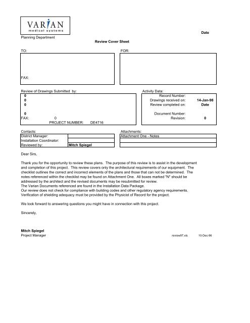
<strong>Planning</strong> <strong>Department</strong><br />
<strong>Review</strong> <strong>Cover</strong> <strong>Sheet</strong><br />
<strong>TO</strong>: <strong>FOR</strong>:<br />
FAX:<br />
<strong>Review</strong> of Drawings Submitted by: Activity Data:<br />
0 Record Number:<br />
0 Drawings received on: 14-Jan-98<br />
0 <strong>Review</strong> completed on: <strong>Date</strong><br />
0 Document Number:<br />
FAX: 0 Revision: 0<br />
PROJECT NUMBER: DE4716<br />
Contacts: Attachments:<br />
District Manager: Attachment One - Notes<br />
Installation Coordinator:<br />
<strong>Review</strong>ed by: Mitch Spiegel<br />
Dear Sirs,<br />
Thank you for the opportunity to review these plans. The purpose of this review is to assist in the development<br />
and completion of this project. This review covers only the architectural requirements of our equipment. The<br />
checklist outlines the correct and incorrect elements of the plans and those that can not be determined. The<br />
notes referenced within the checklist may be found on Attachment One. All boxes marked "N" should be<br />
addressed by the architect and the revised documents may be resubmitted for review.<br />
The <strong>Varian</strong> Documents referenced are found in the Installation Data Package.<br />
Our review does not check for compliance with building codes and other regulatory agency requirements.<br />
Verification of shielding adequacy must be provided by the Physicist of Record for the project.<br />
We look forward to answering questions you might have in connection with this project.<br />
Sincerely,<br />
Mitch Spiegel<br />
Project Manager review97.xls 10-Dec-96<br />
<strong>Date</strong>
<strong>Varian</strong>-Supplied Equipment:<br />
Silhouette<br />
Corresponding Checklist:<br />
CKLSTEX_S<br />
Submitted Documents description:<br />
<strong>Sheet</strong> # <strong>Date</strong> <strong>Sheet</strong> # <strong>Date</strong> <strong>Sheet</strong> # <strong>Date</strong> <strong>Sheet</strong> # <strong>Date</strong><br />
Previous <strong>Planning</strong> <strong>Department</strong> Activity<br />
Description Document # Addressed to: <strong>Date</strong>
varian<br />
<strong>Review</strong> Checklist - Appendix One<br />
item comments<br />
Silhouette Edition Clinac <strong>Review</strong> Notes<br />
1 IN<strong>FOR</strong>MATION COULD NOT BE FOUND ON CONSTRUCTION DOCUMENTS<br />
2 IN<strong>FOR</strong>MATION WAS "SHOWN" BUT NOT DIMENSIONED AND/OR SPECIFIED <strong>FOR</strong> LOCATION<br />
OR CONSTRUCTION.<br />
3 VERIFY ALL SHIELDING AND ROOM PENETRATIONS WITH THE PHYSICIST OF RECORD.<br />
4 VERIFY RIGGING PATH FROM UNLOADING POINT <strong>TO</strong> TREATMENT ROOMS.<br />
5 NEED A NOTE<br />
6 LOCATE ALL INSLAB PULLBOXES AND CONDUIT STUB-UPS<br />
7 SHOW CONTROL EQUIPMENT<br />
8 SHOW LOCATION DETAIL<br />
9 SHOW INTERCONNECTION WIRING DIAGRAM<br />
10<br />
11<br />
12<br />
review97.xls 10-Dec-96
<strong>Varian</strong> <strong>Planning</strong> <strong>Department</strong> Project Drawing <strong>Review</strong><br />
cklstex-s.xls 26-Apr-01<br />
Silhouette Edition Clinac Customer <strong>Varian</strong><br />
Refer to Installation Data Package Notes: Drawing Doc No.<br />
Vault Configuration Section Seven FOC = Face of Concrete Attach. 1 Location [Page No.]<br />
Couch rotation clearance<br />
Recommended 9'-6" clear or 10'-0" FOC 1102305<br />
Acceptable couch has obstruction OR load/unload not optimum [7.25.0]<br />
Unacceptable less than 5'-10" clear 1102303<br />
Cannot be determined [7.23.0]<br />
Gantry ceiling clearance<br />
Recommended at least 9'-0" clear 1102306<br />
Acceptable 8'-8" clear [7.26.0]<br />
Unacceptable less than 8'-8"clear 1102303<br />
Cannot be determined [7.23.0]<br />
Isocenter to back wall distance<br />
Recommended 9'-6" to Face of Concrete 1102305<br />
Acceptable 9'-5" to Face of Concrete [7.25.0<br />
Unacceptable less than 9'-5" clear 1102303<br />
Cannot be determined [7.23.0]<br />
Service clearances at Silhouette Cabinet<br />
Recommended 1102305<br />
Acceptable [7.25.0]<br />
Unacceptable 1102306<br />
[7.26.0]<br />
Entrance Door & Maze<br />
Recommended 48" by 84" net opening - 72" net width passage 1102303<br />
Acceptable 46" by 84" passage - accepted by <strong>Varian</strong> [7.23.0]<br />
Unacceptable inadequate for rigging 1102304<br />
Cannot be determined [7.24.0]<br />
Console Area<br />
Recommended adequate counter area 1102307<br />
Acceptable less than recommended [7.27.0]<br />
Unacceptable inadequate working area 1102308<br />
Cannot be determined [7.28.0]<br />
Isocenter Y N<br />
Isocenter height identified - 4'-3" or 4'-1" 1102306<br />
Isocenter located from two inside walls [7.26.0]<br />
1102303<br />
Silhouette Edition Clinac Page 1 of 5
<strong>Varian</strong> <strong>Planning</strong> <strong>Department</strong> Project Drawing <strong>Review</strong><br />
Customer <strong>Varian</strong><br />
Drawing Doc No.<br />
Treatment Room Location [Page No.]<br />
Accessories and Supplies casework Notes Y N<br />
Space for <strong>Varian</strong>-supplied Applicators 1102310<br />
Space for <strong>Varian</strong>-supplied Wedges [7.30.0]<br />
Space for <strong>Varian</strong>-supplied FFDA's 1102311<br />
Space for Blocks [7.31.0]<br />
Adequate linen/misc. storage space 1102302<br />
Sink and counter [7.22.0]<br />
Console<br />
Control area casework Notes Y N<br />
Counter Height 3'-0" - 3'-4" 1102307<br />
38" deep counter [7.27.0]<br />
Counter length for: 3' Clinac 2' OBI 4' 4DTIC/ Gating<br />
Control Cabinets are spaced with in 15 feet of each other.<br />
Control monitors located with 8 feet of Control / Electronics cabinet<br />
Dedicated four plex outlets 6 Clinac Control Equipment<br />
Clinac Electronics Cabinet Located to the left of the Control Cabinets<br />
Adequate clearance for Clinac Cabinet cooling<br />
Grommets for cables<br />
File or chart storage/Paper & supplies/Personal property<br />
Shielding - <strong>Review</strong> with Physicist Y N<br />
Physicist report included with drawings<br />
Experimental/Physics Access Notes Y N<br />
Routing restricts secondary radiation 1102316<br />
Location verified with Physicist [7.36.0]<br />
Primary beam shielding counterweight Notes Y N<br />
Proper alignment with isocenter no requirements 1102303<br />
12" wider than beam at each side no requirements 1100728<br />
Secondary shielding Notes Y N<br />
location and placement of penetrations restrict secondary radiation 1102303<br />
Door shielding corresponds to Physicist report 1100728<br />
Wall and ceiling shielding correspond to Physicist report [7.23.0]<br />
Pit Configuration<br />
General Notes Y N<br />
isocenter referenced to sides of pit 1102314<br />
Note: "Maintain level floor in 6'-0" radius of isocenter" [7.34.]<br />
Note: "Maintain level floor under Silhouette Cabinet (1/8" in 6'-0")<br />
Rebar shown to avoid anchors<br />
Pit construction Notes Y N<br />
Pit size: 12'-2"LX5'6"WX12"D 1102314<br />
Slab thickness: 8" for anchors [7.34.0]<br />
Seismic details (if required)<br />
Utility valves located and dimensioned at Clinac<br />
Silhouette Edition Clinac Page 2 of 5
<strong>Varian</strong> <strong>Planning</strong> <strong>Department</strong> Project Drawing <strong>Review</strong><br />
Customer <strong>Varian</strong><br />
Drawing Doc No.<br />
Mechanical Location [Page No.]<br />
H.V.A.C. Notes Y N<br />
Ventilation at room for gantry and Silhouette cabinet 1102319<br />
Ventilation at console [7.39.0]<br />
Cooling water Closed Loop system One-Pass Notes Y N<br />
Shut-off Valve in secondary loop 1102319<br />
Domestic water back-up option primary source [7.39.0]<br />
Waste return back-up option primary source<br />
Optional flow gauges on supply/return lines located near Clinac<br />
1" pipe at Clinac utility connection<br />
Valve at Clinac connection<br />
Compressed Air House System New Compressor Notes Y N<br />
1/2" pipe to Clinac 1102319<br />
Air dryer indicated (Instrument Quality Air) [7.39.0]<br />
Oil filter indicated (Instrument Quality Air)<br />
Valve at Clinac utility connection<br />
Final Connections<br />
Plumbing By Customer By <strong>Varian</strong> Notes Y N<br />
"Compressed air connections: Responsibility note" 1102319<br />
"Cooling water connections": Responsibility note [7.39.0]<br />
Electrical<br />
Power supply - Clinac Notes Y N<br />
208VAC three phase- 60Hz(US) 1102318<br />
45 KVA supply capacity [7.38.0]<br />
ground shown at supply transformer or power conditioner<br />
Power Conditioner if required<br />
Power supply - OBI/Trilogy Notes Y N<br />
480VAC three phase- 60Hz(US) 1102318<br />
60 KVA supply capacity [7.38.0]<br />
ground shown at supply transformer or power conditioner<br />
Power Conditioner if required<br />
Power panel - Clinac Notes Y N<br />
Circuit breaker - GE # 2100CBB150A(US) 1102318<br />
UVR - GE 24VDC # TEDUXVERS Included if above is used [7.38.0]<br />
Start button Included if above is used<br />
Bridge rectifier (24VDC, 0.5 amp) Included if above is used<br />
115/24v (US) control transformer Included if above is used<br />
1 amp fuse(US) Included if above is used<br />
Main Circuit Breaker Located within 10 feet of console<br />
Note indicating 8 lin. ft of conductor to be coiled at Silhouette Cabinet<br />
O /<br />
Silhouette Edition Clinac Page 3 of 5
<strong>Varian</strong> <strong>Planning</strong> <strong>Department</strong> Project Drawing <strong>Review</strong><br />
Customer <strong>Varian</strong><br />
Drawing Doc No.<br />
Location [Page No.]<br />
Pull boxes Notes Y N<br />
Access Method bottom side top 1102316<br />
W L D W L D [7.36.0]<br />
Base Frame 12" 24" 10" 12" 24" 22" 1102315<br />
Console 18" 12" 6" 18" 12" 6" [7.35.0]<br />
Conduit Notes Y N<br />
Base to Console three each 4" dia. 1102316<br />
[7.36.0]<br />
Facility Connections<br />
Relay Junction Box (12"x12"x6") 1102316<br />
Two 2" conduits from Relay Junction box to Silhouette Cabinet [7.36.0]<br />
One 1/2" conduit from Relay Junction box to On Board Imager Warning lights<br />
2" conduit from power panel to Silhouette Cabinet<br />
2" conduit from OBI/Trilogy power panel to Silhouette Cabinet<br />
In Room Monitor Notes Y N<br />
2" Conduit with outlet boxes from control area to treatment room 1102313<br />
Bracket/Mounting detail for In Room Monitor<br />
[7.33.0]<br />
Operating and Safety Devices<br />
Conduit routing for required devices Notes Y N<br />
Warning lights to Silhouette Cabinet via relay junction box. C-Series<br />
Door interlocks to Silhouette Cabinet via relay junction box 1102318<br />
Emergency-off switches to Silhouette Cabinet via relay junction box [7.38.0]<br />
Room lights to relay junction box<br />
Laser positioning lights to relay junction box<br />
Control relay Notes Y N<br />
Potter Brumfield - PRD11DG0 - in relay junction box 1102318<br />
Room lights controlled by relay [7.38.0]<br />
Lasers controlled by relay<br />
On Board Imager warning lights controlled by relay<br />
Device locations Notes Y N<br />
Warning light over entrance door 1102317<br />
Warning lights visible from all points in room [7.37.0]<br />
12 volt and 120 volt Door interlocks 1102302<br />
Door activators, if required [7.22.0]<br />
Emergency-off type: Manual reset - normally closed<br />
Emergency-off located outside of primary beam path 1102318<br />
Convenience outlet for each laser positioning light [7.38.0]<br />
Radiation Monitor and Detector (Customer option)<br />
Adequate quantity and location of Room lights<br />
Setup lights located on both sides of couch<br />
Setup lights dimmable and independent of room lights<br />
Silhouette Edition Clinac Page 4 of 5
<strong>Varian</strong> <strong>Planning</strong> <strong>Department</strong> Project Drawing <strong>Review</strong><br />
Lasers supplied by <strong>Varian</strong> supplied by Customer Notes Y N<br />
Overhead laser beam port at Isocenter<br />
Side lasers beam port shown at Isocenter height<br />
Adequate clearance in laser recesses<br />
Side lasers protected from bumping, if not recessed<br />
7'-6" minimum height to sagittal laser beam port<br />
Customer <strong>Varian</strong><br />
Drawing Doc No.<br />
Location [Page No.]<br />
Service provisions Notes Y N<br />
Duplex outlet near Silhouette Cabinet 1102317<br />
[7.37.0]<br />
Console convenience items Notes Y N<br />
Remote Diagnostics phone outlet 1102307<br />
VARiS Network data outlet [7.27.0]<br />
MLC Network data outlet<br />
Telephone outlet<br />
Dimmable console area lighting<br />
Patient intercom provisions by <strong>Varian</strong> (option) Notes Y N<br />
Microphone located near couch 1102317<br />
Signal cable conduit to console [7.37.0]<br />
CCTV provisions camera(s) by <strong>Varian</strong> (option) Notes Y N<br />
Proper location of camera(s) 1102312<br />
Power outlets for camera(s) (120v system only) [7.32.0]<br />
Video cable conduit to console 1102317<br />
Final Connections<br />
Electrical By Customer By <strong>Varian</strong> Notes Y N<br />
"Power connection made:" Responsibility note 1,5 1102318<br />
"Signal connections made:" Responsibility note 1,5 [7.38.0]<br />
"<strong>Varian</strong>-supplied cables pulled:" Responsibility note 1,5<br />
Finishes<br />
Floor Notes Y N<br />
"Install finished floor after equipment is rigged" note 1,5 1102314<br />
Anti-static floor covering specified control console 1,5 [7.34.1]<br />
Anti-static floor covering specified treatment room 1,5<br />
Rigging By Customer By <strong>Varian</strong> Notes Y N<br />
Proper clearances from unloading area to treatment room 1,4 1102304<br />
Rigging clearances require 4-piece breakdown of Clinac 1,4 [7.24.0]<br />
"Install finished floor after equipment is rigged" note 1,4<br />
150 sq. feet secure storage area available during installation note 1,4<br />
Silhouette Edition Clinac Page 5 of 5
<strong>Varian</strong> <strong>Planning</strong> <strong>Department</strong> Project Drawing <strong>Review</strong> cklstgating.xls 12/5/02<br />
]<br />
Respitory Gating Customer <strong>Varian</strong><br />
Refer to Installation Data Package Notes: Drawing Doc No.<br />
Treatment Room Gating Section FOC = Face of Concrete Attach. 1 Location [Page No.]<br />
Camera Position Notes Y N<br />
30 degrees right or left of Isocenter (Plan) G1.0<br />
40 degrees up from Isocenter<br />
Camera positioned between 6 and 14 feet from Isocenter<br />
Camera bracket Wall Ceiling Mounted G7.0<br />
Camera bracket construction detailed<br />
Electrical Notes Y N<br />
1" conduit from camera power supply to Gating Equipment Console G1.0<br />
Standard computer signal cable outlet at each end of conduit<br />
Note: Conduit length not to exceed 75'-0" G7.1<br />
Power Notes Y N<br />
Grounded 120V. 60HZ. Power receptical for Camera power supply G1.0<br />
Power receptical located with in 12" of Camera power supply<br />
Standard wall switch for camera power supply receptical G7.1<br />
Console<br />
Control area casework Notes Y N<br />
Gating Workstation located on Control counter G1.0<br />
20 Amp dedicated quad receptical<br />
Grommets for cables G2.0<br />
Notes Notes Y N<br />
Mounting of Camera power supply by Customer/Contractor G1.0<br />
Mounting of Camera support Bracket by Customer/Contractor<br />
"<strong>Varian</strong>-supplied cables pulled:" Responsibility note G2.0<br />
CT Simulator Notes Y N<br />
Customer supplied wall mount for Gating camera Support Assembly 1.5.0<br />
Customer supplied Curtain rail for Gating Camera cable support<br />
CL2300C/D, 2100C, 2000C/R, 21EX, 23EX Page 1 of 1


![[MSDS 126] Dow Corning 200 Fluid, 5 CST Part Number ... - Varian](https://img.yumpu.com/5104917/1/190x245/msds-126-dow-corning-200-fluid-5-cst-part-number-varian.jpg?quality=85)