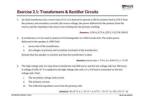
Exercise 2.1: Transformers & Rectifier Circuits
Exercise 2.1: Transformers & Rectifier Circuits
Exercise 2.1: Transformers & Rectifier Circuits

Create successful ePaper yourself
Turn your PDF publications into a flip-book with our unique Google optimized e-Paper software.
<strong>Exercise</strong> <strong>2.1</strong> (cont.)6. i. A voltage source V S is connected to a resistive load R L = 10 Ω by a transmission line having a resistanceR line = 10 Ω, as shown in Figure Q6.1. Determine the power delivered by the source, power lost in the lineresistance, power delivered to the load and the efficiency (expressed as the power delivered to the load asa percentage of power supplied by the source).Figure Q6.1ii. This power transmission system is now modified to include two transformers. A transformer of turnsratio 1:10 is used to step up the source voltage at one end of the transmission line (sending end), andanother transformer of turns ratio 10:1 is used to step down the voltage to 100V at the load (receivingend) as shown in Figure Q6.2. Calculate the power delivered by the source, power lostinthelinethe lineresistance, power delivered to the load and the efficiency in this case, and compare with the valuesobtained in (i) above. What conclusions can you draw from this?Figure Q6.2EG1108 PART 2EXERCISES ~ PAGE 3Answers: i. Efficiency = 50%; ii. Efficiency = 99.01%BEN M. CHEN, NUS ECE
<strong>Exercise</strong> <strong>2.1</strong> (cont.)7. The rectifier supply shown in Figure Q7 is used as part of an electronic circuit. The input voltage issinusoidal with a peak amplitude of 50V, and 10 kHz frequency. The transformer primary to secondaryratio = 1:3. The load resistance is 10kΩ. Neglect diode conduction voltage drops. Also, assume idealoperation of the transformer neglecting leakage, losses etc.i. Determine the output DC voltage. What is the peak‐to‐peak ripple in the output voltage? What isthe percentage ripple?ii.iii.Sketch waveforms for v 1 , v 2 , v 3 , v YX , v o , i o , i 2 , i 3 , v D2 . Mark the diode conduction intervals.What is the maximum reverse voltage applied across the diodes? When do they occur?Figure Q7EG1108 PART 2EXERCISES ~ PAGE 4Answers: i. 47.75 V, 157%; iii. 150VBEN M. CHEN, NUS ECE
<strong>Exercise</strong> <strong>2.1</strong> (cont.)8. A DC power supply consists of a transformer feeding a half‐wave rectifier together with a capacitor filter.It supplies a DC current of 1A at 12V DC to an electronic equipment. The AC input source is 230V (rms)at 50Hz. The output side filter capacitor used is 50000μF.i. Draw the circuit diagram of the supply arrangement.ii.iii.iv.Determine a suitable winding ratio for the transformer. Treat the operation of the power supplyas ideal (i.e., neglect voltage drop in the diode d and assume that t the transformer is ideal).What is the peak‐to‐peak ripple in the output voltage? What is the ripple frequency? What is thepercentage ripple?Sketch the following waveforms: AC input voltage, secondary AC voltage, rectifier output voltage.Mark the interval when the diode conducts.Answers: (ii) 27:1; (iii) % ripple = 3.33%EG1108 PART 2EXERCISES ~ PAGE 5BEN M. CHEN, NUS ECE
<strong>Exercise</strong> 2.2 (cont.)3. The truth table below shows the relationship between inputs A, B and C, and the output Z.i. Find Z in terms of A, B and C using Sum‐of‐products (SOP) form.ii.Use Karnaugh map to simplify the SOP expression derived above.A B C Z0 0 0 10 0 1 10 1 0 00 1 1 11 0 0 01 0 1 11 1 0 01 1 1 0Answers: SOP Expression:Z ABC ABC ABC ABCZ ABBC AC4. Use Karnaugh map to simplify the following Boolean function:F ABCD ABCD ABCD ABCD ABCDAnswer: F AD ABCDEG1108 PART 2EXERCISES ~ PAGE 7BEN M. CHEN, NUS ECE
<strong>Exercise</strong> 2.2 (cont.)5. A Boolean expression is given below:F ABC ABCD ACD ABCD ABCD i. Use rules of Boolean Algebra to simplify this Boolean function.ii.Use Karnaugh map to simplify the Boolean function.Answer:F B C AD6. Use only NOR gates with 2 inputs to find a way to implement the exclusive OR functionZ AB7. From the table shown below, find Z in terms of A, B and C using Product‐of‐sums (POS) form. UseKarnaugh map to simplify the resulting expression.A B C Z0 0 0 10 0 1 00 1 0 00 1 1 11 0 0 01 0 1 11 1 0 01 1 1 0Answer:Z ( AB) ( BC) ( AC) ( ABC)EG1108 PART 2EXERCISES ~ PAGE 8BEN M. CHEN, NUS ECE
<strong>Exercise</strong> 2.2 (cont.)8. Design a logic circuit to control electrical power to the engine ignition of a speed boat.Logic output I is to become high if ignition power is to be applied and remain low otherwise. Gasoline fumesin the engine compartment present a serious hazard of explosion. A sensor provides a logic input F that is highif fumes are present. Ignition power should not be applied if fumes are present. To help prevent accidents,ignition power should not be applied while the outdrive is in gear. Logic signal G is high if the outdrive is ingear and is low otherwise.A blower is provided to clear fumes from the engine compartment and is to be operated for five minutes beforeapplying ignition power. Logic signal B becomes high after the blower has been in operation for five minutes.Finally, an emergency override signal E is provided so that the operator can choose to apply ignition powereven if the blower has not operated for five minutes and if the outdrive is in gear, but not if gasoline fumes arepresent.i. Prepare a truth table listing all combinations of the input signals B, E, F and G. Also show thedesired output I for each row in the table.ii. Using the sum‐of‐products approach, write a Boolean expression for I.iii.Minimize this expression using Karnaugh map.Answer: I EF BFGiv.Implement the logic circuit with the least number of gates (you can assume that AND, OR andNOT gates are available).EG1108 PART 2EXERCISES ~ PAGE 9BEN M. CHEN, NUS ECE