Epsiwall External Wall Insulation System - Wetherby Building Systems
Epsiwall External Wall Insulation System - Wetherby Building Systems
Epsiwall External Wall Insulation System - Wetherby Building Systems

Create successful ePaper yourself
Turn your PDF publications into a flip-book with our unique Google optimized e-Paper software.
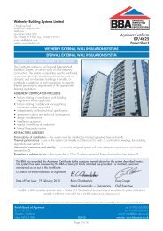
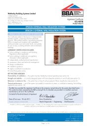
<strong>Wetherby</strong> <strong>Building</strong> <strong>System</strong>s Limited1 Kidglove RoadGolborne Enterprise ParkGolborneGreater Manchester WA3 3GSTel: 01942 717100 Fax: 01942 71710e-mail: info@wbs-ltd.co.ukwebsite: www.wbs-ltd.co.ukAPPROVALINSPECTIONTESTINGCERTIFICATIONTECHNICAL APPROVALS FOR CONSTRUCTIONAgrément Certificate09/4625Product Sheet 2This Agrément Certificate Product Sheet (1) relates to the<strong>Epsiwall</strong> <strong>External</strong> <strong>Wall</strong> <strong>Insulation</strong> <strong>System</strong>, comprisingmechanically-fixed phenolic or enhanced expandedpolystyrene (EPS) boards with specific glassfibrereinforced render finish coats, and suitable for use onnew or existing domestic and non-domestic buildings.(1) Hereinafter referred to as ‘Certificate’.CERTIFICATION INCLUDES:• factors relating to compliance with <strong>Building</strong>Regulations where applicable• factors relating to additional non-regulatoryinformation where applicable• independently verified technical specification• assessment criteria and technical investigations• design considerations• installation guidance• regular surveillance of production• formal three-yearly review.WETHERBY EXTERNAL WALL INSULATION SYSTEMSEPSIWALL EXTERNAL WALL INSULATION SYSTEMKEY FACTORS ASSESSEDThermal performance — use of the system can enable a construction to meet, or contribute to meeting, the buildingregulations (see section 6).Strength and stability — a correctly designed system will have adequate resistance to wind loads (see section 7).Behaviour in relation to fire — the system has a Class 0 surface spread of flame classification (see section 8).Risk of condensation — the system can contribute to limiting the risk of interstitial and surface condensation(see section 11).Durability — with appropriate care, the system will remain effective for at least 30 years (see section 13).The BBA has awarded this Certificate to the company named above for the system described herein. This systemhas been assessed by the BBA as being fit for its intended use provided it is installed, used and maintained as setout in this Certificate.On behalf of the British Board of AgrémentDate of Second issue: 31 July 2013 John Albon — Head of Approvals Claire Curtis-ThomasOriginally certificated on 19 February 2010 Energy and Ventilation Chief ExecutiveThe BBA is a UKAS accredited certification body — Number 113. The schedule of the current scope of accreditation for product certification isavailable in pdf format via the UKAS link on the BBA website at www.bbacerts.co.ukReaders are advised to check the validity and latest issue number of this Agrément Certificate by either referring to the BBA website or contacting the BBA direct.British Board of Agrément tel: 01923 665300Bucknalls Lane fax: 01923 665301Watforde-mail: mail@bba.star.co.ukHerts WD25 9BA©2013website: www.bbacerts.co.ukPage 1 of 16
Regulation: 28(b) Resistance to moisture and weatherComment:The system provides a degree of protection against rain ingress. See sections 4.6 and 10.1 of thisCertificate.Regulation: 29 CondensationComment:The system contributes to minimising the risk of interstitial and surface condensation. See sections 11.2 and11.4 of this Certificate.Regulation: 30 StabilityComment:The system can sustain and transmit wind loads to the substrate wall. See section 7.4 of this Certificate.Regulation: 36(a) <strong>External</strong> fire spreadComment:The system can meet or contribute to meeting this Regulation. See sections 8.1 to 8.3 and 8.6 of thisCertificate.Regulations: 39(a)(i) Conservation measures40 Target carbon dioxide emission rateComment:The system can contribute to satisfying the requirements of these Regulations. See sections 6.2 and 6.3 ofthis Certificate.Construction (Design and Management) Regulations 2007Construction (Design and Management) Regulations (Northern Ireland) 2007Information in this Certificate may assist the client, CDM co-ordinator, designer and contractors to address theirobligations under these Regulations.See section:3 Delivery and site handling (3.1) of this Certificate.Additional InformationNHBC Standards 2013NHBC accepts the use of the <strong>Epsiwall</strong> <strong>External</strong> <strong>Wall</strong> <strong>Insulation</strong> <strong>System</strong>, provided it is installed, used and maintainedin accordance with this Certificate, in relation to NHBC Standards, Chapter 6.9 Curtain walling and cladding.Technical Specification1 Description1.1 The <strong>Epsiwall</strong> <strong>External</strong> <strong>Wall</strong> <strong>Insulation</strong> <strong>System</strong> (see Figure 1) consists of one of two types of insulation which aremechanically fixed to the substrate wall with the reinforcing scrim, cement based basecoat and render finish.1.2 The system (see Figure 1) comprises:• insulation:— phenolic insulation boards — 1200 mm by 600 mm in a range of thicknesses between 20 mm and 130 mm,with a nominal density of 40 kg·m –3 and a minimum compressive strength of 150 kN·m –2 . Boards of 20 mmthickness are also available for use in window reveals.— Epsitherm 70E and 90E — enhanced expanded polystyrene (EPS) 70 and 90 insulation boards — 1200 mmby 600 mm in a range of thicknesses between 40 mm and 240 mm. The boards are manufactured to complywith the requirements for EPS 70, Class E material to BS EN 13163 : 2012 and have a minimum compressivestrength of 70 kN·m –2 and 90 kN·m –2 respectively.• mechanical fixings — proprietary external wall insulation fixings of adequate length to suit the substrate andinsulation thickness, with a minimum 60 mm washer diameter and minimum plate stiffness of 0.6 kN·mm –1 , ETAapproved and supplied by the Certificate holder. Examples include:— Ejotherm NS U— Ejotherm NTK U— SPIT ISO 10— Koelner TFix-8M— Koelner TFix-8S/8ST— Termoz 8U/8UZ— Termoz CN 8.• Heck K+A Basecoat — a cement-based, ready-mixed render conforming to BS EN 13139 : 2002, supplied as apowder to which clean water is added• reinforcing scrim — a multi-stranded, alkali-resistant glassfibre, 4 mm by 4 mm mesh with a polymer coating and anominal weight of 160 gm –2• Heck Universalgrundierung primer — an emulsion used as a bonding agent and precoat• Heck Siliconharputz K and Heck Siliconharputz R render topcoats — silicon ready-mixed pastes available withaggregate sizes from 1.5 mm to 3 mm and 1.5 mm to 2 mm respectively.Page 3 of 16
Figure 1 <strong>Epsiwall</strong> <strong>External</strong> <strong>Wall</strong> <strong>Insulation</strong> <strong>System</strong>1.3 Ancillary items supplied with the system but outside the scope of this Certificate:• profiles — a range of standard profiles, aluminium starter track, stop ends, corner beads, and expansion joint.Profiles are available in stainless or organic polyester powder-coated galvanized steel and are provided to thespecifier’s requirements• profile fixings — hammer screws with plastic expansion• sealant — silicone mastic• end stops• sill extenders• roof verge extenders.Figure 2 Typical section at base levelPage 4 of 16
2 Manufacture2.1 As part of the assessment and ongoing surveillance of product quality, the BBA has:• agreed with the manufacturer the quality control procedures and product testing to be undertaken• assessed and agreed the quality control operated over batches of incoming materials• monitored the production process and verified that it is in accordance with the documented process• evaluated the process for management of nonconformities• checked that equipment has been properly tested and calibrated• undertaken to carry out the above measures on a regular basis through a surveillance process, to verify that thespecifications and quality control operated by the manufacturer are being maintained.2.2 The management system of <strong>Wetherby</strong> <strong>Building</strong> <strong>System</strong>s Limited has been assessed and registered asmeeting the requirements of BS EN ISO 9001 : 2008 and/or BS EN ISO 14001 : 2004 by Bureau Veritas(Certificate UK 9000006).3 Delivery and site handling3.1 Each package carries the product identification, manufacturer’s batch number and the BBA logo incorporating thenumber of this Certificate. The components are delivered to site in the packaging and quantities listed in Table 1.Table 1 Component supply detailsComponent<strong>Insulation</strong>Reinforcing scrimMechanical fixingsBasecoatsPrimer/finish coatQuantity and packagingpolythene wrapped1 metre wide rolls, 50 metre lengthboxed by manufacturer25 kg bag25 kg tub3.2 The insulation must be stored on a firm, clean, level base, off the ground, protected from weather/frost, dry andunder cover until required for use. Care must be taken during handling to avoid damage.3.3 The insulation should be protected from prolonged exposure to sunlight and contact with solvent and bitumen. Theboards must not be exposed to open flame or other ignition sources.3.4 The basecoat must be stored in dry conditions within 5ºC and 30ºC, off the ground and protected from moisture.Contaminated material must be discarded.3.5 The primer and finish coat should be stored in a safe area, under cover, and protected from excessive heat andfrost at all times.Assessment and Technical InvestigationsThe following is a summary of the assessment and technical investigations carried out on the <strong>Epsiwall</strong> <strong>External</strong> <strong>Wall</strong><strong>Insulation</strong> <strong>System</strong>.Design Considerations4 General4.1 The <strong>Epsiwall</strong> <strong>External</strong> <strong>Wall</strong> <strong>Insulation</strong> <strong>System</strong> is effective in reducing the thermal transmittance (U value) of the wallsin new and existing buildings. It is essential that the detailing techniques specified in this Certificate are carried out toa high standard if the ingress of water into the insulation is to be avoided and the full thermal benefit obtained from thesystem.4.2 The system is applied to the outside of external walls of masonry and dense or no-fines concrete constructionand is suitable for use on new or existing domestic or non-domestic buildings up to 18 m in height. Application andmaintenance must be carried out strictly in accordance with this Certificate and the Certificate holder’s instructions, byinstallers trained and approved by the Certificate holder.4.3 The system will improve the weather resistance of a wall and provide a decorative finish. However, it may onlybe installed where other routes for moisture penetration have been dealt with separately and where there are no signsof dampness on the inner surface of the wall, other than those caused solely by condensation.4.4 The insulation system covered by this Certificate does not have provision for movement at joints. The possibleeffects of thermal expansion and differential movement between elements of the substrate, and any consequentprovision for movement joints, should be considered when choosing a suitable insulation system for a particularconstruction.4.5 Existing buildings should have exterior wall surfaces in accordance with section 14 of this Certificate.Page 5 of 16
4.6 New walls subject to the national <strong>Building</strong> Regulations should be constructed in accordance with therelevant recommendations of:• BS EN 1996-1-1 : 2005, BS EN 1996-1-2 : 2005, BS EN 1996-2 : 2006 and BS EN 1996-3 : 2006• BS 5628-3 : 2005, with particular reference to Clause 5.5 Exclusion of water• BS 8000-3 : 2001.4.7 Other walls not subject to regulatory requirements should also be built in accordance with section 4.5.4.8 The fixing of rainwater goods, satellite dishes, clothes lines, hanging baskets and similar items is outside the scopeof this Certificate.4.9 The effect of the installation of the insulation system on the acoustic performance of a construction is also outsidethe scope of this Certificate.4.10 It is essential that the insulation system is installed and maintained in accordance with the conditions set out inthis Certificate.5 Practicability of installationThe system should only be installed by specialised contractors who have successfully undergone training andregistration by the Certificate holder (see section 15).Note: The BBA operates a UKAS Accredited Approved Installer Scheme for external wall insulation; details of installercompanies approved are included on the BBA’s website (www.bbacerts.co.uk).6 Thermal performance6.1 Calculations of thermal transmittance (U value) should be carried out in accordance with BS EN ISO 6946 : 2007and BRE Report BR 443 : 2006, using the declared thermal conductivity of the insulation ( 90/90) as given in Table 2.Table 2 Thermal conductivity values<strong>Insulation</strong> Thickness (mm) 90/90value (W·m –1·K–1 )Epsitherm 70 40 — 240 0.032Epsitherm 90 40 — 240 0.030Phenolic board 40 — 45≥ 450.0210.0206.2 The U value of a completed wall will depend on the selected insulation thickness, the fixing method, andthe insulating value of the substrate masonry and its internal finish. Calculated U values for example constructionsare given in Table 3.Table 3 Thickness of insulation required to achieve typical design values (1)(2)U value (1)(W·m –2·K –1 )0.190.190.19<strong>Insulation</strong> typeEpsitherm 70Epsitherm 90Phenolic<strong>Insulation</strong> thickness requirement(mm) (3)Brickwork, = 0.56 (W·m –1·K–1 ) Dense blockwork, = 1.75 W·m –1·K–1170 mm160 mm110 mm180 mm170 mm110 mm0.260.260.26Epsitherm 70Epsitherm 90Phenolic120 mm110 mm80 mm130 mm120 mm80 mm0.280.280.28Epsitherm 70Epsitherm 90Phenolic110 mm100 mm70 mm120 mm110 mm70 mm0.300.300.30Epsitherm 70Epsitherm 90Phenolic100 mm90 mm60 mm110 mm100 mm70 mm(1) The following values for other elements of the construction were used:• external boundary resistance (R se) — 0.04 m2·W·K –1• render— = 1.0 (W·m –1·K–1 )• 215 mm brickwork (protected) — = 0.56 (W·m –1·K–1 ) (µ = 10) or 200 mm blockwork, = 1.75 (W·m –1·K–1 ) (µ = 100) and 6.7%mortar — = 0.88 (W·m –1·K–1 )• plaster (13 mm) — = 0.57 (W·m –1·K–1 ), µ = 10• internal boundary resistance (R si) — 0.13 m 2·W·K –1 .(2) Fixing regime 5 fixings per board with a point thermal transmittance = 0.003 W·K –1 .(3) Based upon incremental insulation thickness of 10 mm.Page 6 of 16
6.3 The system can contribute to maintaining continuity of thermal insulation at junctions between elements andopenings. Details shown in Figure 2 will allow use of the default psi values for Accredited Construction Details inEmission Rate calculations to SAP 2009 or the Simplified <strong>Building</strong> Energy Model (SBEM). Guidance on limitingheat loss at junctions can be found in:England and Wales — Approved Documents to Part L and for new thermal elements to existing buildings, AccreditedConstruction Details (version 1.0). See also SAP 2009 Appendix K and the iSBEM User Manual for new buildScotland — Accredited Construction Details (Scotland)Northern Ireland — Accredited Construction Details (version 1.0).7 Strength and stability7.1 When installed on suitable walls, the system can adequately transfer to the wall the self-weight and negative(suction) and positive (pressure) wind loads normally experienced in the United Kingdom.7.2 Positive wind load is transferred to the substrate wall directly via bearing and compression of the render andinsulation.7.3 Negative wind pressure (suction) is resisted by the bond between each component. The insulation boards areretained by the external wall insulation system anchors.7.4 The wind loads on the wall should be calculated in accordance with BS EN 1991-1-4 : 2005 and its UKNational Annex. Special consideration should be given to locations with high wind-load pressure coefficients asadditional fixings may be necessary. In accordance with BS EN 1990 : 2002 and UK National Annex, it isrecommended that a load factor of 1.5 is used to determine the ultimate wind load to be resisted by the system.7.5 Assessment of structural performance for individual buildings must be carried out by a suitably qualified andexperienced individual to confirm that:• the substrate wall has adequate strength to resist additional loads that may be applied as a result of installing thesystem, ignoring any contribution that may occur from system• the proposed system and associated fixing layout provides adequate resistance to negative wind loads based onthe results of the site investigation and test results• an appropriate number of site-specific pull-out tests have been conducted on the substrate of the building todetermine the minimum resistance to failure of the fixings. The characteristic pull-out resistance should be determinedin accordance with the guidance given in ETAG 014 : 2002, Annex D.7.6 The number and centres of fixings should be determined by the system designer. Provided the substrate wall issuitable and an appropriate fixing is selected, the mechanical fixings will adequately support and transfer the weight ofthe render insulation system to the substrate wall.7.7 Typical characteristic pull-out strengths for the fixings taken from the corresponding European Technical Approval(ETA) are given in Table 4; however, these values are dependent on the substrate and the fixing must be selected tosuit the loads and substrate concerned.Table 4 Fixings — Typical characteristic pull-out strengthsFixing typePolyethylene with metal centre pin (Ejotherm NT-U and NK-U)Polyethylene with metal centre screw (Ejotherm STR-U and STR-K)Typical pull-out strength (1) (N)12001500(1) Values are determined in accordance with ETAG 014 : 2002 and are dependent on the substrate.7.8 The pull-through resistances determined by BBA from tests are given in Table 5.Table 5 Pull-through resistancesFactor (unit)<strong>Insulation</strong> thickness (mm)Plate diameter of anchor (mm)Characteristic pull-through resistance (1) (per anchor) (N)Factor of safetyDesign pull-through resistance (2) (N)Epsitherm70/9040908332.5333Phenolic50608022.5321(1) Characteristic value in accordance with BS EN 1990 : 2002, Annex D7.2.(2) The safety factor of 2.5 is applied and based on the assumption that all insulation slabs are qualitycontrol tested to establish tensile strength perpendicular to the face of the slab.Impact resistance7.9 Hard body impact tests were carried out and the system is suitable for use in all Use categories (1) .(1) The U se categories are defined in ETAG 004 : 2011 as:• Use category I — a zone readily accessible at ground level to the public and vulnerable to hard body impacts but not subjected toabnormally rough use• Use category II — a zone liable to impacts from thrown or kicked objects, but in public locations where the height of the system will limit thesize of the impact; or at lower levels where access to the building is primarily to those with some incentive to exercise care• Use category III — a zone not likely to be damaged by normal impacts caused by people or by thrown or kicked objects.Page 7 of 16
8 Behaviour in relation to fire8.1 The external surfaces of the system are classified as Class 0 or ‘low risk’ as defined in the national <strong>Building</strong>Regulations.8.2 The phenolic and enhanced EPS insulation materials are not classified as non-combustible.8.3 The system is considered suitable for use on or at any distance from the boundary and restricted for use inbuildings less than 18 m in height.8.4 The system is classified as ‘low risk’ materials and must not be used within 1 m of the boundary and arerestricted for use in buildings less than 18 m in height.8.5 The system is not classified as ‘non-combustible’; therefore, calculations for unprotected areas apply with someminor exceptions.8.6 In all cases, application of the system to second storey walls and above should include at least one stainlesssteel mechanical fixing per square metre and fire barriers installed in line with compartment walls and floors (seeFigure 3). For installation of fire barriers and steel fixings refer to the guidance in BRE Report BR 135 : 2013.Figure 3 Fire break details9 Proximity of flues and appliancesWhen the system is installed in close proximity to certain flue pipes the relevant provisions of the national <strong>Building</strong>Regulations should be met:England and Wales — Approved Document JScotland — Mandatory Standard 3.19, clause 3.19.4 (1)(2)(1) Technical Handbook (Domestic).(2) Technical Handbook (Non-Domestic).Northern Ireland — Technical Booklet L.10 Weathertightness10.1 The system will provide a degree of protection against rain ingress. However, care should be taken toensure that walls are adequately weathertight prior to its application. The insulation system must only be installedwhere there are no signs of dampness on the inner surface of the substrate other than those caused solely bycondensation.10.2 Designers and installers should take particular care in detailing around openings, penetrations and movementjoints to minimise the risk of rain ingress.10.3 Guidance given in BRE Report BR 262 : 2002 should be followed in connection with the weathertightness ofsolid wall constructions. The designer should select a construction appropriate to the local wind-driven index, payingdue regard to the design detailing, workmanship and materials to be used.Page 8 of 16
10.4 At the tops of walls, the system should be protected by an adequate overhang or other detail designed for usewith this type of system.11 Risk of condensation11.1 Designers must ensure that an appropriate condensation risk analysis has been carried out for all parts ofa construction, including at junctions, openings and penetrations to minimise the risk of condensation. Therecommendation of BS 5250 : 2011 should be followed.Surface condensation11.2 <strong>Wall</strong>s will limit the risk of surface condensation adequately when the thermal transmittance (U value) doesnot exceed 0.7 W·m –2·K–1 at any point and the junctions with other elements are designed in accordance withthe relevant requirements of the publications referred to in section 4 of this Certificate.11.3 <strong>Wall</strong>s will adequately limit the risk of surface condensation when the thermal transmittance (U value) doesnot exceed 1.2 W·m –2·K –1 at any point. Guidance may be obtained from BS 5250 : 2011 (Section 4 andAnnex G) and BRE Report BR 262 : 2002.Interstitial condensation11.4 <strong>Wall</strong>s incorporating the system will adequately limit the risk of interstitial condensation when they aredesigned and constructed in accordance with BS 5250 : 2011 (Section 4, Annexes D and G).11.5 The render used with the system has an equivalent air layer thickness (S d) ≤ 1.0 m. This corresponds to a waterresistance factor (µ value) of ≤ 125 for a render thickness of 8 mm.11.6 The water resistance factors (µ value) is 50 for the phenolic (1) and 60 for the enhanced EPS insulation boards, astaken from BS EN 12524 : 2000.(1) The phenolic insulation is faced with glassfibre tissue; this increases the water vapour resistance factor.12 Maintenance and repair12.1 Regular checks should be made on the installed system, including:• visual inspection of the render for signs of damage. Cracks in the render exceeding 0.2 mm must be repaired• examination of the sealant around openings and service entry points• visual inspection of architectural details designed to shed water to confirm that they are performing properly• visual inspection to ensure that water is not leaking from external downpipes or gutters; such leakage couldpenetrate the rendering• necessary repairs effected immediately and the sealant joints at window and door frames replaced at regularintervals• maintenance schedules, which should include the replacement and resealing of joints, for example between theinsulation system and window and door frame.12.2 Damaged areas must be repaired using the appropriate components and the procedures detailed in theCertificate holder’s installation instructions.12.3 Textured finishes may become soiled in time, the rate depending on locality and original colour. Theappearance may be restored by a suitable powerwash or, if required, by the application of a compatible paint.However, great care should be taken not to adversely affect the water vapour or fire resistance characteristics of thesystem. If necessary, the advice of the Certificate holder should be sought.13 Durability13.1 The system should remain effective for at least 30 years, provided any damage to the surface finish isrepaired immediately, and regular maintenance is undertaken as described in section 12.13.2 Any render containing Portland cement may be subject to lime bloom. The occurrence of this may be reducedby avoiding application in adverse weather conditions. The effect is transient and is less noticeable on lighter colours.13.3 The render may become discoloured with time, the rate depending on the initial colour, the degree of exposureand atmospheric pollution, as well as the design and detailing of the wall. In common with traditional renders,discoloration by algae and lichens may occur in wet areas. The appearance may be restored by a suitable powerwash or, if required, by over coating.13.4 To maintain a high quality aesthetic appearance, it may be necessary to periodically overcoat the building usinga suitable masonry coating (ie one covered by a valid BBA Certificate for this purpose). Care should be taken not toadversely affect the water vapour transmission or fire characteristics of the system. The advice of the Certificate holdershould be sought as to the suitability of a particular product.Page 9 of 16
Installation14 Site survey and preliminary work14.1 Before application of the <strong>Epsiwall</strong> <strong>External</strong> <strong>Wall</strong> <strong>Insulation</strong> <strong>System</strong>, a pre-installation survey of the propertyis carried out to determine whether repairs are required to the substrate wall. A specification is prepared for eachelevation of the building indicating, for example:• position of starter tracks and render beads• position and amount of reinforcing scrim and corner mesh• necessity for additional reinforcing scrim at corners of openings• detailing around windows, doors and at eaves• any alterations to external plumbing• dpc level• location and type of weather seals to be used• areas where suitable silicone sealants must be used• position of fire barriers.14.2 Surfaces should be sound, clean, and free from loose material. The flatness of surfaces must be checked; thismay be achieved by using a straight-edge spanning the storey height. Excessive irregularities, ie greater than 10 mm,must be made good prior to installation to ensure that the insulation boards or slabs are installed with a smooth, in-planefinished surface.14.3 A series of tests should be carried out to determine the resistance to pull-out of the proposed fixings (see section 7.8).14.4 On existing buildings, purpose-made sills must be fitted to extend beyond the finished face of the system. Newbuildings should incorporate suitably deep sills.14.5 Internal wet work, eg screeding or plastering, should be completed and allowed to dry prior to the applicationof a system.14.6 Where surfaces are covered with an existing rendering it is essential that the bond between the background andthe render is adequate. All loose areas must be hacked off and reinstated.14.7 In multi-storey at least one fixing per square meter should be of a non-combustible type to provide the increasedstability that may be required in a fire (see section 8.6).14.8 Where mechanical fixings are used to secure the system, trial tests should be conducted on the wall by theCertificate holder to determine the pull-out resistance of the proposed mechanical fixings.14.9 All modifications, such as provision for fire barriers (see section 8.6) and necessary repairs to the building mustbe completed before installation commences.14.10 It is recommended that external plumbing be removed before installation, and any necessary alterations madeto underground drainage to accommodate repositioning of the plumbing on the finished face of the system.15 Approved installersApplication of the system, within the context of this Certificate, must be carried out by approved installers recommendedor recognised by the Certificate holder. Such an installer is a company:• employing operatives who have been trained and approved by the Certificate holder to install the system• which has undertaken to comply with the Certificate holder’s application procedure, containing the requirement foreach application team to include at least one member operative trained by the Certificate holder• subject to at least one inspection per annum by the Certificate holder to ensure suitable site practices are beingemployed. This may include unannounced site inspections.16 ProcedureGeneral16.1 Installation of the system should be carried out in accordance with the Certificate holder’s current installationinstructions.16.2 Application of coating materials must not be carried out at temperatures below 5°C or above 30°C, or ifexposure to frost is likely, and the coating must be protected from rapid drying. Weather conditions, therefore, shouldbe monitored to ensure correct curing conditions.16.3 All rendering should be in accordance with the relevant recommendations of BS EN 13914-1 : 2005 andBS EN 13914-2 : 2005.16.4 Before installation takes place, the building designer must confirm where items such as rainwater goods,satellite dishes, clothes lines and hanging baskets will be placed. The fixing points for these items must be specificallydesignated and built into the system as the insulation is installed. This is outside the scope of this Certificate.Page 10 of 16
Positioning and securing insulation boards16.5 The base profile is secured to the external wall above the damp-proof course (dpc) using the approved profilefixings at approximately 300 mm centres.16.6 The first run of insulation boards is positioned on the base profile. Holes are drilled into the substrate to a minimumrequired depth through each board and layout, as shown in the project specification and drawings (see Figure 4).Figure 4 Typical fixing pattern16.7 The mechanical fixings are inserted and tapped firmly into place securing the insulation board to the substrate.Subsequent rows of boards are positioned so that the joints are staggered and overlapped at the building corners (seeFigure 5).Figure 5 Arrangement of insulation boardsPage 11 of 16
Figure 6 Typical corner detail16.8 Care must be taken to ensure that all insulation board edges are butted tightly together, and alignment ischecked as work proceeds. The surface of the boards should be smooth without high spots or irregularities.16.9 To fit around details such as doors and windows, insulation boards may be cut with a sharp knife or a fine-toothsaw. If required, purpose-made window sills are fitted. They are designed to prevent water ingress and incorporatedrips to shed water clear of the system.16.10 Installation continues until the substrate is completely covered including, where appropriate, the building soffits.Figure 7 Typical opening detailPage 12 of 16
Movement joints16.11 The insulation system covered by this Certificate does not have provision for movement joints (see section 4.4).16.12 Angle beads are fixed to all building corners and to door and window heads and jambs where required.16.13 Stop beads are positioned vertically, eg at party wall positions where the adjoining house does not requiretreatment.Reinforcing, rendering and finishing16.14 The Heck K+A basecoat render is prepared by mixing the contents of each 25 kg bag with approximately 4 to5 litres of cold, clean water, using a paddle mixer. Mixing should continue at least five minutes after the addition of thelast bag of render to allow an even dispersion of the resins.16.15 The mixed basecoat render is trowel-applied to the surface of dry insulation boards to a minimum thickness of4 mm. The reinforcing scrim is bedded into the render with 100 mm laps at joints. Additional reinforcement patchesshould be fitted at corners of windows and doors and similar openings as shown in Figure 8.Figure 8 Corner reinforcement200 x 200 mm glassfibrereinforced mesh scrimwindow opening16.16 Surface mounted PVC render beads are fixed with firtree fixings and bedded in scrim adhesive.16.17 A second coat of Heck K+A Basecoat adhesive is applied to a thickness of between 2 mm and 4 mm andfinished smooth to receive the silicone texture coat.16.18 Continuous surfaces should be completed without a break.16.19 In multi-storey buildings, holes are drilled at 1 m centres for additional fixings before the basecoat hardens,and stainless steel fixings are inserted through the scrim, insulation and into the substrate wall.16.20 Fixings are inserted at 1 m centres through the wet scrim adhesive.16.21 The drying period of any render will depend on weather conditions; however, once applied, the basecoat mustbe left to harden for at least one day before application of the topcoat. When the basecoat render is dry a primer coatis applied. The topcoat is supplied pre-mixed in a tub and is trowel-applied to a thickness of approximately 1.5 mm to3 mm.16.22 The silicone texture render is lightly mixed and applied in an even thickness to the grain size. Prior to setting,the render is polished with a plastic float to give uniform even texture and remove all trowel lines. Elevations should becompleted in one application and finished to natural breaks in render, ie beads or building corners. Texture should bechecked to ensure same batches are applied to each elevation. Where necessary drums can be batch mixed to ensurecolour consistency.16.23 Prior to the render coat, the relevant seals are positioned and installed at all openings (eg windows anddoors), overhanging eaves, gas and electric meter boxes, wall vents or where the render abuts any other buildingmaterial or surface. This helps to reduce the risk of water ingress into the structure.16.24 Care should be taken in the detailing of the system around features such as openings, projections and at eaves(see Figure 9) to ensure adequate protection against water ingress and to limit the risk of water penetrating the system.Page 13 of 16
Figure 9 Typical roof eaves detail — installation on existing buildings17 TestsAn examination was made of data relating to:• resistance to freeze/thaw• heat/spray cycling• impact resistance• water vapour permeability• fire performance• durability of finish coatings• bond strength between basecoat and insulation• pull-through resistance.18 Investigations18.1 The manufacturing process, the methods adopted for quality control of manufactured and bought-in components,and details of the quality and composition of the materials used were examined.18.2 An assessment of the risk of interstitial condensation was undertaken.18.3 The adequacy of fixings and durability of finish was checked.18.4 The practicability of installation and the effectiveness of detailing techniques were examined.Page 14 of 16
BibliographyBS 5250 : 2011 Code of practice for control of condensation in buildingsBS 5628-3 : 2005 Code of practice for the use of masonry — Materials and components, design and workmanshipBS 8000-3 : 2001 Workmanship on building sites — Code of practice for masonryBS 8200 : 1985 Code of practice for design of non-loadbearing external vertical enclosures of buildingsBS EN 1990 : 2002 Eurocode — Basis of structural designNA to BS EN 1990 : 2002 UK National Annex for Eurocode. Basis of structural designBS EN 1996-1-1 : 2005 Eurocode 6 : Design of masonry structures — General rules for reinforced and unreinforcedmasonry structuresBS EN 1996-1-2 : 2005 Eurocode 6 : Design of masonry structures — General rules — Structural fire designBS EN 1996-2 : 2006 Eurocode 6 : Design of masonry structures — Design considerations, selection of materials andexecution of masonryBS EN 1996-3 : 2006 Eurocode 6 : Design of masonry structures : Simplified calculation methods for unreinforcedmasonry structuresBS EN 12524 : 2000 <strong>Building</strong> materials and products — Hygrothermal properties — Tabulated design valuesBS EN 13139 : 2002 Aggregates for mortarBS EN 13163 : 2001 Thermal insulation products for buildings — Factory made products of expanded polystyrene(EPS) — SpecificationBS EN 13914-1 : 2005 Design, preparation and application of external rendering and internal plastering — <strong>External</strong>renderingBS EN 13914-2 : 2005 Design, preparation and application of external rendering and internal plastering — Designconsiderations and essential principles for internal plasteringBS EN ISO 6946 : 2007 <strong>Building</strong> components and building elements — Thermal resistance and thermal transmittance— Calculation methodBS EN ISO 9001 : 2008 Quality management systems — RequirementsBS EN ISO 14001 : 2004 Environmental Management systems — Requirements with guidance for useBRE Report (BR 135 : 2003 ) Fire Performance of <strong>External</strong> <strong>Insulation</strong> For <strong>Wall</strong>s of Multi-Storey <strong>Building</strong>sBRE Report (BR 262 : 2002 ) Thermal insulation: avoiding risksBRE Report (BR 443 : 2006) Conventions for U-value calculationsETAG 004 : 2011 Guideline for European Technical Approval of <strong>External</strong> Thermal <strong>Insulation</strong> Composite <strong>System</strong>s withRenderingETAG 014 : 2002 Guideline for European Technical Approval of Plastic Anchors for fixing of <strong>External</strong> Thermal<strong>Insulation</strong> Composite <strong>System</strong>s with RenderingPage 15 of 16
Conditions of Certification19 Conditions19.1 This Certificate:• relates only to the product/system that is named and described on the front page• is issued only to the company, firm, organisation or person named on the front page — no other company, firm,organisation or person may hold or claim that this Certificate has been issued to them• is valid only within the UK• has to be read, considered and used as a whole document — it may be misleading and will be incomplete to beselective• is copyright of the BBA• is subject to English Law.19.2 Publications, documents, specifications, legislation, regulations, standards and the like referenced in this Certificateare those that were current and/or deemed relevant by the BBA at the date of issue or reissue of this Certificate.19.3 This Certificate will remain valid for an unlimited period provided that the product/system and its manufactureand/or fabrication, including all related and relevant parts and processes thereof:• are maintained at or above the levels which have been assessed and found to be satisfactory by the BBA• continue to be checked as and when deemed appropriate by the BBA under arrangements that it will determine• are reviewed by the BBA as and when it considers appropriate.19.4 The BBA has used due skill, care and diligence in preparing this Certificate, but no warranty is provided.19.5 In issuing this Certificate, the BBA is not responsible and is excluded from any liability to any company, firm,organisation or person, for any matters arising directly or indirectly from:• the presence or absence of any patent, intellectual property or similar rights subsisting in the product/system or anyother product/system• the right of the Certificate holder to manufacture, supply, install, maintain or market the product/system• actual installations of the product/system, including their nature, design, methods, performance, workmanship andmaintenance• any works and constructions in which the product/system is installed, including their nature, design, methods,performance, workmanship and maintenance• any loss or damage, including personal injury, howsoever caused by the product/system, including its manufacture,supply, installation, use, maintenance and removal• any claims by the manufacturer relating to CE marking.19.6 Any information relating to the manufacture, supply, installation, use, maintenance and removal of this product/system which is contained or referred to in this Certificate is the minimum required to be met when the product/systemis manufactured, supplied, installed, used, maintained and removed. It does not purport in any way to restate therequirements of the Health and Safety at Work etc. Act 1974, or of any other statutory, common law or other dutywhich may exist at the date of issue or reissue of this Certificate; nor is conformity with such information to be taken assatisfying the requirements of the 1974 Act or of any statutory, common law or other duty of care.British Board of Agrément tel: 01923 665300Bucknalls Lane fax: 01923 665301Watforde-mail: mail@bba.star.co.ukHerts WD25 9BA©2013website: www.bbacerts.co.ukPage 16 of 16