Epsiwall External Wall Insulation System - British Board of Agrement
Epsiwall External Wall Insulation System - British Board of Agrement
Epsiwall External Wall Insulation System - British Board of Agrement

You also want an ePaper? Increase the reach of your titles
YUMPU automatically turns print PDFs into web optimized ePapers that Google loves.
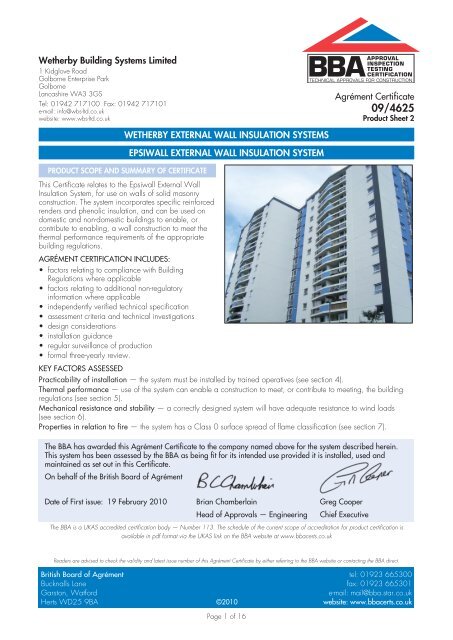
Wetherby Building <strong>System</strong>s Limited1 Kidglove RoadGolborne Enterprise ParkGolborneLancashire WA3 3GSTel: 01942 717100 Fax: 01942 717101e-mail: info@wbs-ltd.co.ukwebsite: www.wbs-ltd.co.ukAPPROVALINSPECTIONTESTINGCERTIFICATIONTECHNICAL APPROVALS FOR CONSTRUCTIONAgrément Certificate09/4625Product Sheet 2WETHERBY EXTERNAL WALL INSULATION SYSTEMSEPSIWALL EXTERNAL WALL INSULATION SYSTEMPRODUCT SCOPE AND SUMMARY OF CERTIFICATEThis Certificate relates to the <strong>Epsiwall</strong> <strong>External</strong> <strong>Wall</strong><strong>Insulation</strong> <strong>System</strong>, for use on walls <strong>of</strong> solid masonryconstruction. The system incorporates specific reinforcedrenders and phenolic insulation, and can be used ondomestic and non-domestic buildings to enable, orcontribute to enabling, a wall construction to meet thethermal performance requirements <strong>of</strong> the appropriatebuilding regulations.AGRÉMENT CERTIFICATION INCLUDES:• factors relating to compliance with BuildingRegulations where applicable• factors relating to additional non-regulatoryinformation where applicable• independently verified technical specification• assessment criteria and technical investigations• design considerations• installation guidance• regular surveillance <strong>of</strong> production• formal three-yearly review.KEY FACTORS ASSESSEDPracticability <strong>of</strong> installation — the system must be installed by trained operatives (see section 4).Thermal performance — use <strong>of</strong> the system can enable a construction to meet, or contribute to meeting, the buildingregulations (see section 5).Mechanical resistance and stability — a correctly designed system will have adequate resistance to wind loads(see section 6).Properties in relation to fire — the system has a Class 0 surface spread <strong>of</strong> flame classification (see section 7).The BBA has awarded this Agrément Certificate to the company named above for the system described herein.This system has been assessed by the BBA as being fit for its intended use provided it is installed, used andmaintained as set out in this Certificate.On behalf <strong>of</strong> the <strong>British</strong> <strong>Board</strong> <strong>of</strong> AgrémentDate <strong>of</strong> First issue: 19 February 2010 Brian Chamberlain Greg CooperHead <strong>of</strong> Approvals — Engineering Chief ExecutiveThe BBA is a UKAS accredited certification body — Number 113. The schedule <strong>of</strong> the current scope <strong>of</strong> accreditation for product certification isavailable in pdf format via the UKAS link on the BBA website at www.bbacerts.co.ukReaders are advised to check the validity and latest issue number <strong>of</strong> this Agrément Certificate by either referring to the BBA website or contacting the BBA direct.<strong>British</strong> <strong>Board</strong> <strong>of</strong> Agrément tel: 01923 665300Bucknalls Lane fax: 01923 665301Garston, Watforde-mail: mail@bba.star.co.ukHerts WD25 9BA©2010website: www.bbacerts.co.ukPage 1 <strong>of</strong> 16
RegulationsIn the opinion <strong>of</strong> the BBA, the <strong>Epsiwall</strong> <strong>External</strong> <strong>Wall</strong> <strong>Insulation</strong> <strong>System</strong>, if used in accordance with the provisions <strong>of</strong>this Certificate, will meet or contribute to meeting the relevant requirements <strong>of</strong> the following Building Regulations:The Building Regulations 2000 (as amended) (England and Wales)Requirement: A1Comment:Requirement: B4(1)Comment:Requirement: C2(b)(c)Comment:Requirement: L1(a)(i)Comment:Requirement: Regulation 7Comment:LoadingThe system can sustain and transmit wind loads to the substrate wall. See sections 6.4 and 6.8 <strong>of</strong> thisCertificate.<strong>External</strong> fire spreadThe system is classified Class 0 and can, therefore, meet this Requirement. See sections 7.1 to 7.4, and7.6 <strong>of</strong> this Certificate.Resistance to moisture<strong>Wall</strong>s incorporating the system can meet this Requirement. See section 9.3 <strong>of</strong> this Certificate.Conservation <strong>of</strong> fuel and powerThe system can enable or contribute to enabling a construction to meet the Target Emission Rate. Seesections 5.3 and 5.4 <strong>of</strong> this Certificate.Materials and workmanshipThe system is acceptable. See section 12.1 and the Installation part <strong>of</strong> this Certificate.The Building (Scotland) Regulations 2004 (as amended)Regulation: 8(1)(2) Fitness and durability <strong>of</strong> materials and workmanshipComment:The use <strong>of</strong> the system satisfies the requirements <strong>of</strong> this Regulation. See sections 11.1 and 12.1 and theInstallation part <strong>of</strong> this Certificate.Regulation: 9 Building standards — constructionStandard 1.1 StructureComment:The system can sustain and transmit wind loads to the substrate wall. See sections 6.4 and 6.8 <strong>of</strong> thisCertificate.Standard: 2.6 Spread to neighbouring buildingsComment:The system has a ‘low risk’ surface classification. The system incorporates materials which would not beclassed as ‘non-combustible’. Completed walls, therefore, would be regarded as unprotected areas asdefined in this Standard, with reference to clauses 2.6.1 (1)(2) , 2.6.2 (1)(2) , 2.6.4 (1)(2) , 2.6.5 (1) and 2.6.6 (2) .See sections 7.1 to 7.4, and 7.6 <strong>of</strong> this Certificate.Standard: 2.7 Spread on external wallsComment:The system incorporates materials which would not be classed as ‘non-combustible’ as defined in thisStandard under clauses 2.7.1 (1)(2) and 2.7.2 (2) and should not, therefore, be used on walls one metre orless from a boundary. See sections 7.1 to 7.4, and 7.6 <strong>of</strong> this Certificate.Standard: 3.10 PrecipitationComment:<strong>Wall</strong>s insulated with the system can satisfy this Standard, with reference to clauses 3.10.1 (1)(2) and3.10.6 (1)(2) . See section 9.3 <strong>of</strong> this Certificate.Standard: 3.15 CondensationComment:<strong>Wall</strong>s insulated with the system can satisfy the requirements <strong>of</strong> this Standard, with reference to clauses3.15.1 (1) , 3.15.4 (1) and 3.15.5 (1) . See sections 10.4 and 10.5 <strong>of</strong> this Certificate.Standards: 6.1(b) Carbon dioxide emissions6.2 Building insulation envelopeComment: The system can contribute to satisfying these Standards, with reference to clauses (or parts <strong>of</strong>) 6.1.1 (1) ,6.1.2 (1)(2) , 6.1.3 (2) , 6.1.5 (2) , 6.1.6 (1) , 6.2.1 (1) , 6.2.3 (1) , 6.2.4 (1) , 6.2.5 (1)(2) and 6.2.10 (2) . See sections5.3 and 5.4 <strong>of</strong> this Certificate.(1) Technical Handbook (Domestic).(2) Technical Handbook (Non-Domestic).The Building Regulations (Northern Ireland) 2000 (as amended)Regulation: B2 Fitness <strong>of</strong> materials and workmanshipComment:The system is acceptable. See section 12.1 and the Installation part <strong>of</strong> this Certificate.Regulation: B3(2) Suitability <strong>of</strong> certain materialsComment:The system is acceptable. See section 11.1 <strong>of</strong> this Certificate.Regulation: C4(b) Resistance to ground moisture and weatherComment:<strong>Wall</strong>s insulated with the system can satisfy this Regulation. See section 9.3 <strong>of</strong> this Certificate.Regulation: C5 CondensationComment:<strong>Wall</strong>s insulated with the system can satisfy the requirements <strong>of</strong> this Regulation. See sections 10.4 and10.5 <strong>of</strong> this Certificate.Regulation: D1 StabilityComment:The system can sustain and transmit wind loads to the substrate wall. See sections 6.4 and 6.8 <strong>of</strong> thisCertificate.Page 2 <strong>of</strong> 16
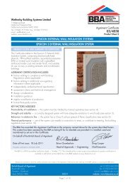
Regulation: E5(a) <strong>External</strong> fire spreadComment: The system has a Class 0 classification surface and can satisfy this Regulation. See sections 7.1 to 7.4,and 7.6 <strong>of</strong> this CertificateRegulations: F2(a)(i) Conservation measuresF3(2)Target carbon dioxide Emissions RateComment:The system can enable a construction to meet the requirements <strong>of</strong> these Regulations. See sections 5.3 and5.4 <strong>of</strong> this Certificate.Construction (Design and Management) Regulations 2007Construction (Design and Management) Regulations (Northern Ireland) 2007Information in this Certificate may assist the client, CDM co-ordinator, designer and contractors to address theirobligations under these Regulations.See section: 2 Delivery and site handling (2.1).Non-regulatory InformationNHBC Standards 2008NHBC accepts the use <strong>of</strong> the <strong>Epsiwall</strong> <strong>External</strong> <strong>Wall</strong> <strong>Insulation</strong> <strong>System</strong> for masonry walls, when installed and used inaccordance with this Certificate, in relation to NHBC Standards, Chapter 6.9 Curtain walling and cladding.GeneralThis Certificate relates to the <strong>Epsiwall</strong> <strong>External</strong> <strong>Wall</strong> <strong>Insulation</strong> <strong>System</strong> for use on external walls <strong>of</strong> masonry construction.The system incorporates specific reinforced renders and phenolic insulation, and can be used on new and existingdomestic and non-domestic buildings.Technical Specification1 Description1.1 The insulation system is for use on external walls <strong>of</strong> masonry construction. It is mechanically fixed using anchorsthat have been approved by the Certificate holder.1.2 The insulation systems covered by this Certificate do not have provision for movement at joints. The possibleeffects <strong>of</strong> thermal expansion and differential movement between elements <strong>of</strong> the substrate and any consequent provisionfor movement at joints should be considered when choosing a suitable insulation system for a particular construction.1.3 The effect <strong>of</strong> the installation <strong>of</strong> the system on the acoustic performance <strong>of</strong> a construction is outside the scope <strong>of</strong> thisCertificate.1.4 The components <strong>of</strong> the basic wall system (see Figures 1 and 2) from outer to inner comprise:• Heck Siliconharputz K and Heck Siliconharputz R render topcoats — silicon ready-mixed pastes available withaggregate sizes from 1.5 mm to 3 mm and 1.5 mm to 2 mm respectively• Heck Universalgrundierung primer — an emulsion used as a bonding agent and precoat• Heck K+A Basecoat — a cement-based, ready-mixed render conforming to BS EN 13139 : 2002, supplied as apowder to which clean water is added• reinforcing scrim — a multi-stranded, alkali-resistant, glassfibre, 4 mm by 4 mm mesh, with a polymer coating and anominal weight <strong>of</strong> 160 g·m –2• mechanical fixing — an anchor <strong>of</strong> adequate length to suit the insulation thickness and incorporating a 60 mmdiameter plate• Kingspan Kooltherm K5EWB insulation – phenolic insulation boards faced with a glassfibre tissue, size 1200 mmby 600 mm, in thicknesses ranging from 40 mm to 90 mm, with a density <strong>of</strong> 50 kg·m –3 and a conductivity <strong>of</strong>between 0.021 and 0.020 W·m –1·K–1 .Page 3 <strong>of</strong> 16
Figure 1 <strong>Epsiwall</strong> external wall insulation system for masonrywalls — typical section at base levelFigure 2 Typical fixing patternPage 4 <strong>of</strong> 16
1.5 Ancillary items supplied by the Certificate holder for use in particular locations/forms <strong>of</strong> construction include:• starter tracks (to suit each insulation thickness)• end stops• sill extenders• ro<strong>of</strong> verge extenders.1.6 Ancillary items which are outside the scope <strong>of</strong> this Certificate and not supplied by the Certificate holder, but whichmay be required to ensure the completed construction complies with the building regulations and is fit for purpose,include:• sealant • fire stops • cavity stops (where required, see section 7.6).2 Delivery and site handling2.1 Components are delivered in the packaging and quantities listed in Table 1. Each basecoat bag carries theproduct identification and manufacturer’s batch number.Table 1 Component supply detailsComponent<strong>Insulation</strong>Reinforcing scrimBasecoatsPrimerFinish coatMechanical fixingsQuantity and packagingpolythene wrapped1 metre wide rolls, 50 metre length25 kg bag15 kg tub25 kg tubboxed by manufacturer2.2 The insulation must be protected from prolonged exposure to sunlight either by storing opened packs under coveror re-covering with opaque sheeting. In addition, the insulation should be stored on a firm, clean, level base, <strong>of</strong>f theground and under cover until required for use. Care must be taken when handling the insulation boards to avoidboth damage and contact with solvents or bitumen products. The boards must not be exposed to open flame or otherignition sources.2.3 The basecoat must be stored in dry conditions, <strong>of</strong>f the ground, and protected from moisture and frost.Assessment and Technical InvestigationsThe following is a summary <strong>of</strong> the assessment and technical investigations carried out on the <strong>Epsiwall</strong> <strong>External</strong> <strong>Wall</strong><strong>Insulation</strong> <strong>System</strong>.Design Considerations3 General3.1 The <strong>Epsiwall</strong> <strong>External</strong> <strong>Wall</strong> <strong>Insulation</strong> <strong>System</strong> comprises the system components described in section 1.3.2 The system is effective in reducing the thermal transmittance (U value) <strong>of</strong> the walls in new and existing buildings. Itis essential that the detailing techniques specified in this Certificate are carried out to a high standard if the ingress <strong>of</strong>water into the insulation is to be avoided and the full thermal benefit obtained from the system.3.3 The system will improve the weather resistance <strong>of</strong> a wall and provide a decorative finish. However, it may onlybe installed where other potential sources <strong>of</strong> moisture penetration have been dealt with separately and where there areno signs <strong>of</strong> dampness on the inner surface <strong>of</strong> the wall, other than those caused solely by condensation. The system canbe used to overcome condensation occurring on an internal wall surface.3.4 Existing buildings, subject to national Building Regulations, should have exterior wall surfaces in accordance withsection 13 Site survey and preliminary work in the Installation part <strong>of</strong> this Certificate.3.5 New walls subject to national Building Regulations should be constructed in accordance with the relevantrecommendations <strong>of</strong>:• BS 5628-3 : 2005 (in particular, clause 5.5.2 Rain penetration <strong>of</strong> the Code <strong>of</strong> Practice, should be followed in thatthe designer should select a construction appropriate to the local wind-driven rain index, paying due regard to thedesign detailing, workmanship and materials to be used)• BS 8000-3 : 2001.3.6 Other walls not subject to regulatory requirements should also be built in accordance with section 3.4.3.7 When using the system, the recommendations <strong>of</strong> BS 5250 : 2002 should be followed and consideration given tothe overall design to minimise the risk <strong>of</strong> condensation.Page 5 <strong>of</strong> 16
4 Practicability <strong>of</strong> installationThe system should only be installed by contractors trained and approved by the Certificate holder and in accordancewith the Certificate holder’s Installation Manual (see section 14).5 Thermal performance5.1 Calculations <strong>of</strong> thermal transmittance (U value) should be carried out in accordance with BS EN ISO 6946 :2007 and BRE report (BR 443 : 2006) Conventions for U-value calculations, using the declared thermal conductivity <strong>of</strong>the insulation (λ 90/90 ) as given in Table 2.5.2 The U value <strong>of</strong> a completed wall will depend on the selected insulation thickness, the fixing method, and the insulatingvalue <strong>of</strong> the substrate masonry and its internal finish. Calculated U values for example constructions are given in Table 3.5.3 When considering insulation requirements, designers should refer to the detailed guidance contained in thedocuments supporting the national Building Regulations. The U values shown in Table 4 indicate that the product canenable a wall to achieve typical design U values referred to in those supporting documents (see Tables 4 and 5).New buildings5.4 <strong>Wall</strong>s with U values lower than (or the same as, for dwellings in Scotland) the relevant ‘notional’ valuespecified in Tables 4 or 5 will contribute to a building meeting its Target Emission Rate. <strong>Wall</strong>s with higherU values will require additional energy saving measures in the building envelope and/or services.5.5 The system can maintain, or contribute to maintaining, continuity <strong>of</strong> thermal insulation around openings and atjunctions between external walls and other building elements.5.6 For existing buildings, extensions and conversions, walls will be acceptable where they do not exceed therelevant U value in Tables 4 or 5 and junctions and openings comply with section 5.5 or BRE report (BR 262 : 2002)Thermal insulation: avoiding risks.Table 2 Thermal conductivity values<strong>Insulation</strong> Thickness (mm) λ 90/90value (W·m –1·K –1 )Phenolic board (40 kg·m –3 density) 40–45≥450.0210.020Table 3 Example wall U value (W·m –2·K –1 ) (1)<strong>Insulation</strong> thickness (mm)5060708090200 mm <strong>of</strong> dense concrete( = 1.75 W·m –1·K –1 )13 mm <strong>of</strong> dense plaster( = 0.57 W·m –1·K –1 )0.480.360.300.250.22220 mm <strong>of</strong> brickwork( = 0.56 W·m –1·K –1 )13 mm <strong>of</strong> dense plaster( = 0.57 W·m –1·K –1 )0.420.330.270.240.21(1) Including eight steel fixings <strong>of</strong> 5.5 mm diameter per metre, steel= 50 W·m –1·K –1 .Table 4 Typical design values for walls — England, Wales and Northern IrelandU value(W·m –2·K –1 )0.300.350.350.70Construction typeMean for new extensions‘notional’ mean in SAP and SBEM and limit mean for new-buildLimit mean for replacement (1) , renovation (1) and retained (1) wallsIndividual limit for new-build and flexible approaches(1) Details <strong>of</strong> alternative/flexible approaches are given in relevant document supporting the national Building Regulations.Table 5 Typical design U values for walls — ScotlandU value(W·m –2·K –1 )0.200.250.270.300.70Construction type‘notional’ mean for dwellings in SAP and the ‘simplified’ approach:— solid fuel, package 6— other fuels, packages 1 to 5Limit mean for new extensions, conversions (1) , alterations (1) and reconstructions (1)‘notional’ mean for non-domestic buildings in SBEM and limit mean for new-buildIndividual limit for new-build, new extensions, conversions, alterations and reconstructions(1) Details <strong>of</strong> alternative/flexible approaches are given in relevant document supporting the national Building Regulations.Page 6 <strong>of</strong> 16
6 Mechanical resistance and stabilityGeneral6.1 Installations incorporating the insulation system can be designed to provide adequate resistance to design loadsapplicable to some areas <strong>of</strong> the UK.6.2 Positive wind load (pressure) is transferred to the substrate wall directly via bearing and compression <strong>of</strong> the render,insulation and adhesive.6.3 Negative wind pressure (suction) is resisted by the bond between each component; the insulation boards areretained by the ETICS anchor and secured to the wall with the appropriate fixing screws.6.4 The wind loads on the wall should be calculated in accordance with BS EN 1991-1-4 : 2005 orBS 6399-2 : 1997. Special consideration should be given to locations with high wind-load pressure coefficientsas additional fixings may be necessary. In accordance with BS EN 1990 : 2002, it is recommended that aload factor <strong>of</strong> 1.5 is used to determine the ultimate wind load to be resisted by the system.6.5 Assessment <strong>of</strong> structural performance for individual buildings should be carried out by a suitably qualified engineeror other appropriately qualified person to confirm that:• the substrate wall has adequate strength to resist additional loads that may be applied as a result <strong>of</strong> installing thesystem, ignoring any contribution from the insulation system• the proposed system and associated fixing layout provides adequate resistance to negative wind loads (based onthe results <strong>of</strong> the site investigation) (see section 6.7).6.6 Provided the substrate wall is suitable and an appropriate fixing is used, the mechanical fixings and starter trackat the base will transfer the weight <strong>of</strong> the render insulation system to the substrate wall. The number <strong>of</strong> fixings and thespan between fixings should be determined by the system designer. The fixing must be selected to give adequatesupport to the weight <strong>of</strong> the system at the minimum spacing given in this Certificate.6.7 Tests carried out by the BBA indicate that a fixing with a 60 mm diameter anchor plate <strong>of</strong> adequate stiffness willhave an ultimate pull-over resistance <strong>of</strong> 550 N. An example wind loading calculation relating to the fixing patterndetailed in Figure 2 can be seen in Table 6. Site-specific tests should be conducted on the substrate walls <strong>of</strong> thebuilding to determine the actual pull-out resistance <strong>of</strong> the fixings. This should be the required minimum <strong>of</strong> five testsdivided by a factor <strong>of</strong> safety <strong>of</strong> 3.Table 6 <strong>Epsiwall</strong> example wind loading calculation (1)Factor Actual resistance force Required resistance forceCalculated wind load (Pa) (2)750Ultimate wind load (Pa) (3)1125Anchor pull-over resistance (N) (4)550Panel design pull-over resistance (N) (5)183.33Approximate anchor pull out resistance (N) (6)1000Anchor design pull out resistance (7)333.3Limiting resistance (N) (8)183.33Resistance force (N) (9)916.67Resistance force required (N) (10) 810.00666999550183.331000333.3183.33916.67719.28(1) The calculation is based on an insulation board measuring 1200 mm x 600 mm (total area 0.72 m 2 ) attached by five fixings.(2) See section 6.4.(3) Calculated wind load x wind load factor <strong>of</strong> 1.5.(4) Pull resistance <strong>of</strong> the insulation over the head <strong>of</strong> a fixing (see section 6.7).(5) Pull-over resistance/EWIS safety factor <strong>of</strong> 3.(6) See section 6.7.(7) Anchor pull-out resistance/EWIS safety factor <strong>of</strong> 3.(8) This is the lesser <strong>of</strong> the panel design pull-over resistance and the anchor design pull-out resistance.(9) This is based upon the limiting resistance, in this case 183.33 x 5.(10) This is the ultimate wind load x panel area.Impact loading6.8 Hard body impact tests were carried out generally in accordance with MOAT No 22 : 1988. It isrecommended that the use <strong>of</strong> the system is restricted to category E (1) as defined in BS 8200 : 1985,Table 2.(1) 1.5 m to 6 m above pedestrian or floor level in location categories A and B defined as follows:• Category A — readily accessible to the public and others with little incentive to exercise care; prone to vandalism and abnormally roughuse, eg external walls <strong>of</strong> housing and public buildings in vandal prone areas• Category B — readily accessible to the public and others with little incentive to exercise care; risk <strong>of</strong> accidents occurring and <strong>of</strong> misuse,eg walls adjacent to pedestrian thoroughfares or playing fields when not in category A.Page 7 <strong>of</strong> 16
7 Properties in relation to fire7.1 The white external surfaces <strong>of</strong> the system are classified as Class 0 or ‘low risk’ as defined in the documentssupporting the national Building Regulations. The system, therefore, may be used in accordance with theprovisions <strong>of</strong>:England and Wales — Approved Document B, Volume 1, paragraph 8.4, and Volume 2, paragraph 12.6 (see alsoApproved Document B, Volume 2, Diagram 40).Scotland — Mandatory Standards 2.6 and 2.7, clauses 2.6.1 (1)(2) to 2.6.5 (1)(2) , 2.6.6 (2) , 2.6.7 (2) , 2.7.1 (1)(2) and2.7.2 (2) respectively, and Annexes 2.C (1) and 2.E (2)(1) Technical Handbook (Domestic).(2) Technical Handbook (Non-Domestic).Northern Ireland — Technical Booklet E, paragraph 4.3 (see also Diagram 4.1).7.2 The classifications stated in section 7.1 were achieved on light-coloured render (further details can be obtainedfrom the Certificate holder). However, the classification <strong>of</strong> darker colours should be confirmed by:England and Wales — test or assessment in accordance with Approved Document B, Appendix A, Clause 1Scotland — test to conform with Regulation 9, Annex 2.C (1) , Table, and Annex 2.E (2)(1) Technical Handbook (Domestic).(2) Technical Handbook (Non-Domestic).Northern Ireland — test or assessment by a UKAS accredited laboratory or an independent consultant withappropriate experience.7.3 The documents listed in section 5.1 give full details <strong>of</strong> permissible heights and boundary conditions <strong>of</strong> domesticand non-domestic buildings and the relevant guidance with regard to external wall claddings <strong>of</strong> external wall insulationsystems with render surfaces. However, the following information is <strong>of</strong>fered for guidance purposes:England and Wales• for buildings one metre or more from a boundary, the systems are acceptable• for buildings less than one metre from a boundary, the systems can be acceptable provided the wall meets the fireresistance requirements in Tables A1 and A2, from both sides• the systems can be acceptable, subject to the aforementioned conditions, for use on a building which has a floor upto and over 18 m above the ground level.Scotland• domestic and non-domestic use – for buildings more than one metre from a boundary, up to 18 m above groundlevel, the systems can be acceptable. The systems are not classified as non-combustible, therefore calculations forunprotected areas apply (1) .(1) Combustible cladding need not be included in the calculation for unprotected areas where it is attached to the structure <strong>of</strong> the building and theexternal wall does not contain openings other than the small openings described in Mandatory Standard 2.6.2, clause 2.6.2b, and the wallbehind the cladding has the appropriate fire-resistance duration from the inside. In Mandatory Standard 2.6, clause 2.6.2b, an unprotectedarea is defined as an area <strong>of</strong> not more than 0.1 m –2 which is at least 1.5 m from any other unprotected area in the same wall.Northern Ireland• for buildings one metre or more from a boundary, the systems are acceptable• for buildings less than one metre from a boundary, the systems can be acceptable provided the wall meets the fireresistance requirements given in Tables 3.1 and 3.2, from both sides• the systems are acceptable, subject to the aforementioned conditions, for use on a building which has a storey thefloor <strong>of</strong> which is up to 18 m above the ground level. For a building which has a storey the floor <strong>of</strong> which is 18 m ormore above the ground level, there is an additional requirement for the insulation component to be <strong>of</strong> a material <strong>of</strong>limited combustibility.7.4 To limit the risk <strong>of</strong> fire spread between floors cavity barriers should be installed at each floor level above thefirst floor (ie starting with the second storey) as detailed in BRE report (BR 135 : 2003) Fire Performance <strong>of</strong> <strong>External</strong><strong>Insulation</strong> for <strong>Wall</strong>s <strong>of</strong> Multi-storey Buildings (see Figure 3). Vertical cavity barriers should also be installed in line withcompartment walls.Page 8 <strong>of</strong> 16
Figure 3 Cavity barrier7.5 In buildings not subject to the Building Regulations, it is recommended that designers should consider the use <strong>of</strong>the guidance given in section 6.2.7.6 Any cavities present within the system, such as those formed between the external wall insulation systemand the substrate, must have an appropriate fire stop or cavity barrier in accordance with the relevant clauses orsections <strong>of</strong>:England and Wales — Approved Document B, Volume 1, Section 6, and Volume 2, Section 9Scotland — Mandatory Standards 2.4, 2.6 and 2.7, clauses 2.1.4 (1)(2) , 2.4.2 (1)(2) , 2.4.7 (1) , 2.4.9 (2) , 2.6.1 (1)(2) to2.6.5 (1)(2) , 2.6.6 (2) , 2.6.7 (2) , 2.7.1 (1)(2) and 2.7.2 (2) respectively, and Annex 2.A (1)(1) Technical Handbook (Domestic).(2) Technical Handbook (Non-Domestic).Northern Ireland — Technical Booklet E, Section 3, paragraphs 3.35 to 3.39, and Section 4.8 Proximity <strong>of</strong> flues and appliancesWhen the system is installed in close proximity to certain flue pipes the relevant provisions <strong>of</strong> the national BuildingRegulations should be met:England and Wales — Approved Document JScotland — Mandatory Standard 3.19, clause 3.19.4 (1)(2)(1) Technical Handbook (Domestic).(2) Technical Handbook (Non-Domestic).Northern Ireland — Technical Booklet L.9 Rain penetration9.1 The system will provide a degree <strong>of</strong> protection against rain ingress. However, care should be taken to ensurethat walls are adequately weathertight prior to the application <strong>of</strong> the system. The system may only be installed wheredampness (other than that caused solely by condensation) is not evident on the inner surface <strong>of</strong> the substrate.9.2 Designers and installers should take particular care over detailing around openings, penetrations and movementjoints, to minimise the risk <strong>of</strong> rain ingress.9.3 Guidance in BS 5628-3 : 2005, Table 11, indicates that externally insulated single-leaf masonry walls(minimum 90 mm thick) are acceptable in exposure categories up to ‘severe’. Additional guidance can befound in:England and Wales — Approved Document C, Section 5Scotland — Mandatory Standard 3.10 (1)(2)(1) Technical Handbook (Domestic).(2) Technical Handbook (Non-Domestic).Northern Ireland — Technical Booklet C, Section 2.9.4 At the tops <strong>of</strong> walls, the system should be protected by an adequate overhang or other detail designed for usewith this type <strong>of</strong> system (see section 15.20).9.5 The fixing <strong>of</strong> rainwater goods, satellite dishes, clothes lines, hanging baskets and similar items is outside the scope<strong>of</strong> this Certificate.9.6 It is essential that the system is installed and maintained in accordance with the conditions set out in this Certificate.10 Condensation10.1 Designers should ensure that an appropriate condensation risk analysis has been carried out for all parts <strong>of</strong> aconstruction, including openings and penetrations, to ensure condensation does not occur.Page 9 <strong>of</strong> 16
Surface condensation10.2 <strong>Wall</strong>s will limit the risk <strong>of</strong> surface condensation adequately when the thermal transmittance (U value) does notexceed 0.7 W·m –2·K–1 at any point and the junctions with other elements and openings comply with section 5.5.10.3 <strong>Wall</strong>s will adequately limit the risk <strong>of</strong> surface condensation when the thermal transmittance (U value) does notexceed 1.2 W·m –2·K–1 at any point. Guidance may be obtained from BS 5250 : 2002, Section 8, and BRE report(BR 262 : 2002) Thermal insulation : avoiding risks.Interstitial condensation10.4 The components <strong>of</strong> the system have a water vapour resistance such that, under the types <strong>of</strong> conditionswhich may occur in dwellings in the United Kingdom, interstitial condensation should not occur within theinsulation.10.5 If a system is to be used on the external walls <strong>of</strong> rooms expected to have continuous high humidities, care must betaken in the design <strong>of</strong> the rooms to avoid possible problems from the formation <strong>of</strong> interstitial condensation in the wall.10.6 <strong>Wall</strong>s incorporating the systems will adequately limit the risk <strong>of</strong> interstitial condensation when designed andconstructed in accordance with BS 5250 : 2002 (Section 8 and Annex D).10.7 The render used with the systems has an equivalent air layer thickness (S d) ≤ 1 m. This corresponds to a waterresistance factor (µ value) <strong>of</strong> ≤ 125 for a render thickness <strong>of</strong> 8 mm.10.8 The water resistance factor (µ value) for the insulation boards, as taken from BS EN 12524 : 2000, is 50.11 Maintenance11.1 As part <strong>of</strong> a maintenance programme, regular inspections should be made on the installed system toensure that ingress <strong>of</strong> water does not occur. Such programmes should include the replacement and resealing <strong>of</strong>joints, eg those between the insulation system and window and door frames. The interval between inspectionsshould be considered on a building-by-building basis taking into consideration, for example, such factors as thebuilding location and height. Any necessary repairs should be put into effect immediately.11.2 The designer should ensure appropriate provision for access is available to enable maintenance inspections totake place safely.11.3 Damaged areas must be repaired using the appropriate components; the Certificate holder should be contactedfor further information.12 Durability12.1 The results <strong>of</strong> accelerated ageing tests in accordance with MOAT No 22 : 1988 indicate that the systemis durable. The system should remain effective for at least 30 years, provided any damage to the surface finish isrepaired immediately, and regular maintenance is undertaken (see section 11). This includes checks on joints inthe systems and on penetrations to enable corrective action to be taken to rectify the defects.12.2 The finish may become discoloured with time. The rate at which this occurs will depend on the initial colour,the degree <strong>of</strong> exposure, the level <strong>of</strong> atmospheric pollution and the design and detailing <strong>of</strong> the wall. In common withtraditional renders, discoloration by algae and lichens may occur in wet areas.Installation13 Site survey and preliminary work13.1 Before application <strong>of</strong> the <strong>Epsiwall</strong> <strong>External</strong> <strong>Wall</strong> <strong>Insulation</strong> <strong>System</strong>, a pre-installation survey <strong>of</strong> the propertyis carried out to determine whether repairs are required to the substrate wall. A specification is prepared for eachelevation <strong>of</strong> the building indicating, for example:• position <strong>of</strong> starter tracks and render beads• position and amount <strong>of</strong> reinforcing scrim and corner mesh• necessity for additional reinforcing scrim at corners <strong>of</strong> openings• detailing around windows, doors and at eaves• any alterations to external plumbing• dpc level• location and type <strong>of</strong> weather seals to be used• areas where suitable silicone sealants must be used• position <strong>of</strong> fire barriers.13.2 Surfaces should be sound, clean, and free from loose material. The flatness <strong>of</strong> surfaces must be checked; thismay be achieved by using a straight-edge spanning the storey height. Excessive irregularities, ie greater than 10 mm,must be made good prior to installation to ensure that the insulation boards or slabs are installed with a smooth,in-plane finished surface.Page 10 <strong>of</strong> 16
13.3 On existing buildings, purpose-made sills must be fitted to extend beyond the finished face <strong>of</strong> the system. Newbuildings should incorporate suitably deep sills.13.4 Internal wet work, eg screeding or plastering, should be completed and allowed to dry prior to the application<strong>of</strong> a system.13.5 Where surfaces are covered with an existing rendering it is essential that the bond between the background andthe render is adequate. All loose areas must be hacked <strong>of</strong>f and reinstated.13.6 In buildings <strong>of</strong> more than two storeys at least one fixing per insulation board should be <strong>of</strong> a non-combustibletype to provide the increased stability that may be required in a fire (see section 15.11).13.7 Where mechanical fixings are to be used to secure the system, trial tests should be conducted on the wall bythe Certificate holder or their approved applicators (see section 14) to determine the pull-out resistance <strong>of</strong> the proposedmechanical fixings.13.8 All modifications, such as provision for cavity barriers and fire stopping (see section 7) and necessary repairs tothe building must be completed before installation commences.13.9 It is recommended that external plumbing be removed before installation, and any necessary alterations made tounderground drainage to accommodate repositioning <strong>of</strong> the plumbing on the finished face <strong>of</strong> the system.14 Approved installersApplication <strong>of</strong> the systems, within the context <strong>of</strong> this Certificate, must be carried out by installers approved by theCertificate holder. A Certificate-holder approved installer is a company which:• employs operatives who have been trained and approved by the Certificate holder to install the systems and who,upon completion <strong>of</strong> their training, have been issued with an appropriate identification card by the Certificate holder• has undertaken to comply with the Certificate holder’s installation procedure, including the requirement for eachinstallation team to include at least one member with an identification card• agrees to be subject to supervision and site inspections by the Certificate holder.15 ProcedureGeneral15.1 Installation <strong>of</strong> the system should be carried out in accordance with the Certificate holder’s current installationinstructions.15.2 Application <strong>of</strong> coating materials must not be carried out at temperatures below 5°C or above 30°C, or ifexposure to frost is likely, and the coating must be protected from rapid drying. Weather conditions, therefore, shouldbe monitored to ensure correct curing conditions.15.3 All rendering should be in accordance with the relevant recommendations <strong>of</strong> BS EN 13914-1 : 2005 andBS EN 13914-2 : 2005.15.4 Before installation takes place, the building designer must confirm where items such as rainwater goods,satellite dishes, clothes lines and hanging baskets will be placed. The fixing points for these items must be specificallydesignated and built into the system as the insulation is installed. This is outside the scope <strong>of</strong> this Certificate.15.5 The base pr<strong>of</strong>ile is secured to the external wall above the damp pro<strong>of</strong> course using mechanical fixings at aminimum <strong>of</strong> 300 mm centres.Positioning and securing insulation boards15.6 The first insulation board is positioned on the starter track and secured into the substrate wall using a mechanicalfixing. Subsequent boards are positioned so that the joints are staggered and overlapped at the building corners (seeFigures 4 and 5). Care must be taken to ensure the fixings are not overdriven.Figure 4 Arrangement <strong>of</strong> insulation boards and typical fixing patternPage 11 <strong>of</strong> 16
Figure 5 Typical corner detail15.7 Care must be taken to ensure that all insulation board edges are butted tightly together, and alignment ischecked as work proceeds. The surface <strong>of</strong> the boards should be smooth without high spots or irregularities.15.8 To fit around details such as doors and windows, insulation boards may be cut with a sharp knife or a fine-toothsaw. Purpose-made window sills, seals and deflection channels, designed to prevent or manage water ingress andallow water to be shed clear <strong>of</strong> items bridging the cavity, should be fitted (see Figure 6).Figure 6 Typical opening detailinsulation boardapproved mechanicalfixingsmasonry substratemasonry substrateapprovedmechanicalfixinginsulationboardPVC corner bead beddedon adhesive mortarframe seal or siliconesealant at abutmentPVC corner bead beddedon adhesive mortarconjectured line <strong>of</strong> windowframe seal or siliconesealant at abutmentreduced thickness <strong>of</strong> insulationboard mechanically fixed tomasonry substrate. Detail subjectto site constraints and window details.conjectured line <strong>of</strong> existing window15.9 Installation continues until the substrate is completely covered including, where appropriate, the building s<strong>of</strong>fits.Movement joints15.10 The insulation systems covered by this Certificate do not have provision for movement joints (see section 1.2).Page 12 <strong>of</strong> 16
Reinforcing15.11 In buildings <strong>of</strong> more than two storeys, holes are drilled at 1 m centres for additional fixings before the basecoathardens, and stainless steel fixings are inserted through the scrim, insulation and into the substrate wall.15.12 Fixings are inserted into the centre <strong>of</strong> each board through the wet scrim adhesive.Rendering and finishing15.13 Prior to the render coat, the relevant seals are positioned and installed at all openings (eg windows anddoors), overhanging eaves, gas and electric meter boxes, wall vents or where the render abuts any other buildingmaterial or surface. This helps to reduce the risk <strong>of</strong> water ingress into the structure.15.14 The Heck K+A basecoat render is prepared by mixing the contents <strong>of</strong> each 25 kg bag with approximately 4to 5 litres <strong>of</strong> cold, clean water, using a paddle mixer. Mixing should continue at least five minutes after the addition <strong>of</strong>the last bag <strong>of</strong> render to allow an even dispersion <strong>of</strong> the resins.15.15 The mixed basecoat render is trowel-applied to the surface <strong>of</strong> dry insulation boards to a minimum thickness <strong>of</strong>4 mm. The scrim is bedded into the render with 100 mm laps at joints. Additional reinforcement should be applied atcorners <strong>of</strong> windows and doors as shown in Figure 7.Figure 7 Corner reinforcement15.16 The drying period <strong>of</strong> any render will depend on weather conditions; however, once applied, the basecoatmust be left to harden for at least one day before application <strong>of</strong> the topcoat. The topcoat is supplied pre-mixed in a tuband is trowel-applied to a thickness <strong>of</strong> approximately 2 to 4 mm.15.17 Surface mounted PVC render beads are fixed with firtree fixings and bedded in scrim adhesive.15.18 A second coat <strong>of</strong> Heck K+A Basecoat adhesive is applied to a thickness <strong>of</strong> between 2 mm and 4 mm andfinished smooth to receive the silicone texture coat.15.19 When the basecoat render is dry a primer coat is applied.15.20 Care should be taken in the detailing <strong>of</strong> the system around features such as openings, projections and at eaves(see Figure 8) to ensure adequate protection against water ingress and to limit the risk <strong>of</strong> water penetrating the system.Page 13 <strong>of</strong> 16
Figure 8 Typical ro<strong>of</strong> eaves detail — installation on existing building15.21 The silicone texture render is lightly mixed and applied in an even thickness to the grain size. Prior to setting,the render is polished with a plastic float to give uniform even texture and remove all trowel lines. Elevations should becompleted in one application and finished to natural breaks in render, ie beads or building corners. Texture should bechecked to ensure same batches are applied to each elevation. Where necessary drums can be batch mixed to ensurecolour consistency.Technical Investigations16 Tests16.1 Tests were carried out in accordance with MOAT No 22 : 1988 to determine:• heat/spray cycling• resistance to freeze/thaw• impact resistance.16.2 An examination was made <strong>of</strong> data relating to:• adequacy <strong>of</strong> the fixing system• durability <strong>of</strong> finish.16.3 The practicability <strong>of</strong> installation and the effectiveness <strong>of</strong> typical details were examined.17 InvestigationsAn examination was made <strong>of</strong> the manufacturing process, the methods adopted for quality control <strong>of</strong> manufacture andbought-in components, and details <strong>of</strong> the quality and composition <strong>of</strong> the materials usedPage 14 <strong>of</strong> 16
BibliographyBS 5250 : 2002 Code <strong>of</strong> practice for control <strong>of</strong> condensation in buildingsBS 5628-3 : 2005 Code <strong>of</strong> practice for the use <strong>of</strong> masonry — Materials and components, design and workmanshipBS 6399-2 : 1997 Loading for buildings — Code <strong>of</strong> practice for wind loadsBS 8000-3 : 2001 Workmanship on building sites — Code <strong>of</strong> practice for masonryBS 8200 : 1985 Code <strong>of</strong> practice for design <strong>of</strong> non-loadbearing external vertical enclosures <strong>of</strong> buildingsBS EN 1990 : 2002 Eurocode. Basis <strong>of</strong> structural designBS EN 1991-1-4 : 2005 Eurocode 1 : Actions on structures — General actions — Wind actionsBS EN 12524 : 2000 Building materials and products — Hygrothermal properties — Tabulated design valuesBS EN 13139 : 2002 Aggregates for mortarBS EN 13914-1 : 2005 Design, preparation and application <strong>of</strong> external rendering and internal plastering — <strong>External</strong>renderingBS EN 13914-2 : 2005 Design, preparation and application <strong>of</strong> external rendering and internal plastering — Designconsiderations and essential principles for internal plasteringBS EN ISO 6946 : 2007 Building components and building elements — Thermal resistance and thermal transmittance— Calculation methodMOAT No 22 : 1988 UEAtc Directives for the Assessment <strong>of</strong> <strong>External</strong> <strong>Insulation</strong> <strong>System</strong>s for <strong>Wall</strong>s (ExpandedPolystyrene <strong>Insulation</strong> Faced with a Thin Rendering)Page 15 <strong>of</strong> 16
Conditions <strong>of</strong> Certification18 Conditions18.1 This Certificate:• relates only to the product/system that is named and described on the front page• is granted only to the company, firm or person named on the front page — no other company, firm or person mayhold or claim any entitlement to this Certificate• is valid only within the UK• has to be read, considered and used as a whole document — it may be misleading and will be incomplete to beselective• is copyright <strong>of</strong> the BBA• is subject to English law.18.2 Publications and documents referred to in this Certificate are those that the BBA deems to be relevant at the date<strong>of</strong> issue or re-issue <strong>of</strong> this Certificate and include any: Act <strong>of</strong> Parliament; Statutory Instrument; Directive; Regulation;<strong>British</strong>, European or International Standard; Code <strong>of</strong> Practice; manufacturers’ instructions; or any other publication ordocument similar or related to the aforementioned.18.3 This Certificate will remain valid for an unlimited period provided that the product/system and the manufactureand/or fabrication including all related and relevant processes there<strong>of</strong>:• are maintained at or above the levels which have been assessed and found to be satisfactory by the BBA• continue to be checked as and when deemed appropriate by the BBA under arrangements that it will determine• are reviewed by the BBA as and when it considers appropriate.18.4 In granting this Certificate, the BBA is not responsible for:• the presence or absence <strong>of</strong> any patent, intellectual property or similar rights subsisting in the product/system or anyother product/system• the right <strong>of</strong> the Certificate holder to manufacture, supply, install, maintain or market the product/system• individual installations <strong>of</strong> the product/system, including the nature, design, methods and workmanship <strong>of</strong> or relatedto the installation• the actual works in which the product/system is installed, used and maintained, including the nature, design,methods and workmanship <strong>of</strong> such works.18.5 Any information relating to the manufacture, supply, installation, use and maintenance <strong>of</strong> this product/systemwhich is contained or referred to in this Certificate is the minimum required to be met when the product/system ismanufactured, supplied, installed, used and maintained. It does not purport in any way to restate the requirements<strong>of</strong> the Health & Safety at Work etc Act 1974, or <strong>of</strong> any other statutory, common law or other duty which may existat the date <strong>of</strong> this Certificate; nor is conformity with such information to be taken as satisfying the requirements <strong>of</strong> the1974 Act or <strong>of</strong> any statutory, common law or other duty <strong>of</strong> care. In granting this Certificate, the BBA does not acceptresponsibility to any person or body for any loss or damage, including personal injury, arising as a direct or indirectresult <strong>of</strong> the manufacture, supply, installation, use and maintenance <strong>of</strong> this product/system.<strong>British</strong> <strong>Board</strong> <strong>of</strong> Agrément tel: 01923 665300Bucknalls Lane fax: 01923 665301Garston, Watforde-mail: mail@bba.star.co.ukHerts WD25 9BA©2010website: www.bbacerts.co.ukPage 16 <strong>of</strong> 16