ZL180 Z SERIES - Came UK
ZL180 Z SERIES - Came UK
ZL180 Z SERIES - Came UK

You also want an ePaper? Increase the reach of your titles
YUMPU automatically turns print PDFs into web optimized ePapers that Google loves.
CONTROL PANEL FOR 24V OPERATORSZ <strong>SERIES</strong>INSTALLATION MANUAL<strong>ZL180</strong>
“IMPORTANT INSTALLATION, SAFETY INSTRUCTIONS”“CAUTION: IMPROPER INSTALLATION MAY CAUSE SERIOUS DAMAGE, FOLLOW ALL INSTALLATION INSTRUCTIONS CAREFULLY”“THIS MANUAL IS ONLY FOR PROFESSIONAL INSTALLERS OR QUALIFIED PERSONS”1 Legend of symbolsENGLISHThis symbol indicates sections to be read with particular care.This symbol indicates sections concerning safetyThis symbol indicates notes to communicate to users.2 Intended use and application2.1 Intended useThe <strong>ZL180</strong> control panel is designed to control the F7024N, A3024N and A5024N swing gate operators.The use of this product for purposes other than as described above and installation executed in a manner other thanas instructed in this technical manual are prohibited.2.2 ApplicationMake sure you respect the distances and cable diameters as shown in “cable types and minimal thicknesses” table.The overall power of the motors must not exceed 300W.3 Reference StandardsFor its quality processes management <strong>Came</strong> Cancelli Automatici is ISO 9001:2000 certified, and for its environmentalmanagement it is ISO 14001 certified. <strong>Came</strong> designs and manufactures entirely in Italy.This product complies with the following standards: see chapter 12 - Conformity declaration - pag. 13.4 DescriptionThis product is engineered and manufactured by CAME cancelliautomatici s.p.a. and complies with current safety regulations.Guaranteed24 months if not tampered with.The control panel works on 230V a.c. of power, through theterminals L-N, 50/60Hz frequency.Both command and control devices and accessories are 24Vpowered.Warning! Accessories must not exceed 34 W overall.The control unit is fi tted with an amperometric device whichconstantly regulates the motor’s drive coefficient.When the gate runs into an obstacle, the amperometric sensorimmediately detects an overcharge in the drive and redirectsthe gate’s direction of movement, and:opens it if it is closing (1) ;closes it if it is opening.(1) Warning!: in this case, after 3 consecutive obstacledetections, the gate will stop open excluding the automaticclosing function; for movement to start again press thecommand button or use the remote control.All connections are protected by quick fuses, see table.The card provides and controls the following functions:- automatic closing after an open-command;- pre-fl ashing by the motion indicator;- obstacle detection when gate is still in any position;- continual monitoring of photocell operation.The following command modes are possible:- open/close;- open/close and maintained action;- partially open;- complete stop.2After detecting an obstacle, the photocells will:- reopen the gate if it is closing;- partially stop it if it is opening.Apposite trimmers regulate:- the automatic closing run time;- the second gate leaf’s motion time difference;- the amperometric device’s detection sensitivity, inseparately in terms of normal opening and closing andbraking.TECHNICAL FEATURESPower supplymax. rated powerPower draw when idlingMax power of 24V accessoriesInsulation ratingMaterialProtection ratingoperating temperatureFUSESprotectionMotor/sElectronic board (power supply line)AccessoriesControl devices230V - 50/60Hz300W85mA34WIIABSIP54-20 / +55°Cfuse type5A-F1A-F1.6A-F630mA-FThe data and information in this catalogue may change without prior notice from CAME cancelli automatici s.p.a.
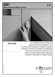
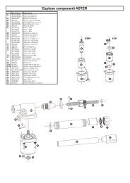
4.1 Dimensions, spans and anchoring holesENGLISH (mm)4.2 Main components1 - Transformer2 - Control unit fuse13 - Trimmers (see page 9)The data and information in this catalogue may change without prior notice from CAME cancelli automatici s.p.a.4 - Buttons for memorising the radio code5 - Plug for the remote control frequencycard6 - Terminal board for connecting the antenna7 - Terminal board for connecting accessoriesand control devices8 - Terminal board for connecting the gearmotors9 - Terminal board for 230V a.c. power grid10 - Line fuse11 - M1 motor fuse12 - M2 motor fuse13 - Accessories fuse14 - Fucntions selector15 - Control and signalling LED unitWarning! Before acting on themachinery, cut off the main power supplyand disconnect any emergency batteries.WhiteBlack9VioletOrangeGrey10 11 12 138RedBlueBrown15142YellowYellow357 643
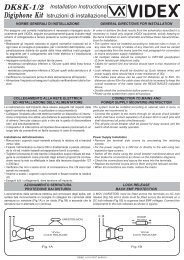
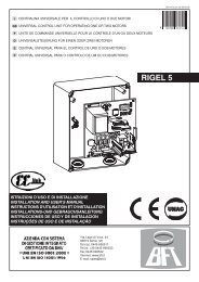
5 Installation5.1 Preliminary checksENGLISHBefore installing do the following:• Check that the panel’s anchoring point is protected from possible blows, and that the anchoring surface is solid. Also checkthat the anchoring is done using the appropriate bolts, screws etc.• Make sure you have a suitable omnipolar cut-off device with contacts more than 3 mm apart, and independent (sectionedoff) power supply.• Make sure that any connections inside the case (that provide continuance to the protective circuit) are fitted with extrainsulation as compared to the other conductive parts inside;• Make sure you have suitable tubing and conduits for the electrical cables to pass through and be protected againstmechanical damage.5.2 Tools and materialsMake sure you have all the tools and materials you will need for the installation at hand to work in total safety andcompliance with the current standards and regulations. The following figure illustrates the minimum equipment needed bythe installer.5.3 Fixing and mounting the box2154Fix the base of the panel in a protected area; we suggestusing round top Phillips recessed head screws of max.6mm in diameter.Perforate the pre-punched holes and insert the cableglands with the corrugated tubing for the electrical cablesto travel throughN.B.: the pre-punched holes have the following diameters:23m 29 and 37 mm.Assemble the pressure hinges.295!!The data and information in this catalogue may change without prior notice from CAME cancelli automatici s.p.a.
Insert the pressure hinges into the box (onthe left or right as you wish) and set themusing the provided screws and washers15 mm~They must slide in order to turnENGLISHSnap the cover into place onto the hinges. Close it and fix it using theprovided screwsThe data and information in this catalogue may change without prior notice from CAME cancelli automatici s.p.a.After the adjustments and settings, fix the cover using theprovided screws.6 Electrical connections6.1 Cable list and minimum thicknessesConnectionsControl panel power supply 230VTypeof cableLength of cable1 < 10 mLength of cable10 < 20 mLength of cable20 < 30 m3G x 1,5 mm 2 3G x 2,5 mm 2 3G x 4 mm 2Motor power supply 24V 2 x 1 mm 2 2 x 1,5 mm 2 2 x 2,5 mm 2flashing lamp FROR CEI 2 x 0,5 mm 2 2 x 1 mm 2 2 x 1,5 mm 220-22Transmitter photocells 2 x 0,5 mm 2 2 x 0.5 mm 2 2 x 0,5 mm 2CEI ENReceiver photocells 4 x 0,5 mm50267-2-14 x 0,5 mm 2 4 x 0,5 mm 2Power supply to accessories 2 x 0,5 mm 2 2 x 0,5 mm 2 2 x 1 mm 2Control and safety devices 2 x 0,5 mm 2 2 x 0,5 mm 2 2 x 0,5 mm 2Antenna connection RG58 max. 10 mN.B.: If the cable length differs from that specified in the table, then you must determine the proper cable diameter based onthe actual power draw from the connected devices and according to the CEI EN 60204-1 standards.For connections that require several, sequential loads, the sizes given on the table must be re-evaluated based on actualpower draw and distances.When connecting products that are not specified in this manual, please follow the documentation provided with saidproducts.5
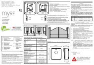
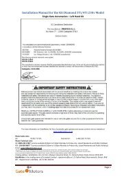
GearmotorClosing-speedreduction microswitch24V d.c. gearmotor featuringdelayed action on opening24V d.c. gearmotor featuringdelayed action on closingENGLISHOpening-speedblocker microswitchWhiteRedWhiteRedBlackRedWhiteRedWhiteRedRedBlack6Power supply to accessoriesTerminals for powering the following accessories:- 24V a.c. (normally alternated power)- 24V a.c. (continuous power) when the emergency batteries arein operation.Overall power allowed: 34WPower supply230V (a.c.) 50/60 HzSignalling and Lighting devicesSignal Flasher (socket rating: 24V - 25W max.)Flashes during opening and closing phasesOpen gate indicator-light (socket rating: 24V - 3W max.).Turns on when the gate is ajar or open.It turns off when the gate is closed.+-The data and information in this catalogue may change without prior notice from CAME cancelli automatici s.p.a.
Safety devicesRXDIR photocellsTX“partial stop” (N.C.) socket- input for safety devices such as photocells, sensitiveedges and other EN 12978-compliant devices. Haltsmoving gate leaves and causes them to automaticallycloseENGLISHRXDIR photocellsTX“Open during closing” (N.C.) socket- Input for safety devices such as photocells, sensitiveedges and other EN 12978 compliant devices.When gate leaves are closing, opening the contactcauses reversal until total opening is obtained.The data and information in this catalogue may change without prior notice from CAME cancelli automatici s.p.a.“Partial Stop” (N.C.) socket“Open during closing” (N.C.) socketRXTX RXDOC photocellsDOC photocellsTX 7
Command devicesPulsante Stop button (N.C. socket)- PulsanteButton to stop gate while excluding the automatic closingcycle. For movement to resume you must press the commandbutton or transmitter button.ENGLISHKey selector and/or partial opening button (N.O. socket)- Opening of one gate leaf to allow pedestrian passage.Key selector and/or commands button (N.O. contact)- Gate closing and opening contacts, by pressing the button orturning the selector key, the gate movement is inverted or halteddepending on which selection was just made. (see selectingfunctions, dips 2 and 3).86.2 Electrical connection for the photocells functions test(DOC) (DIR) At each opening and closing command, the control board assessesthe effi ciency status of the control devices (photocells). Any anomalyfound is signalled with the fl ashing of the (PROG) LED on the controlpanel. Consequently it cancels any commands coming from the remotecontrol or the button.Electrical connection to enable the photocell safety test:- the transmitter and the receiver, must be connected as per the diagram;- set DIP switch 9 to ON to activate test operation.IMPORTANT:when running the safety test function, the N.C. contacts, if unused, should be excluded on the relative DIP switches (seechapter 7 “selecting functions”). The data and information in this catalogue may change without prior notice from CAME cancelli automatici s.p.a.
7 Selecting functionsDIP-SWITCHONDefault settingThe data and information in this catalogue may change without prior notice from CAME cancelli automatici s.p.a.1 ON - Automatic closing - the automatic closing timer is activated when on opening the gate leaf has reached the full openstroke. The time is preset and adjustable, and is subject to the action of any safety devices. It does not activate aftera total safety “stop” or during a power outage;2 ON - “Open-stop-close-stop” function with button [2-7] and remote control (with built-in radiofrequency card);2 OFF - “Open-close” function with button [2-7] and remote control (with built-in radiofrequency card);3 ON - “Open only” function with remote control (featuring built-in radiofrequency card);OFF 4 ON - Pre-Flashing during opening and closing - Following an opening or closing command, the flasher connected to [10-E],flashes for 5 seconds before initiating the operation;5 ON - Obstacle detection - When motor is idle (gate closed, open or after a total stop command), it prevents any motion ifthe safety devices (e.g. photocells) detect any obstacle;6 ON - Maintained action - the gate works by keeping the button pressed (one button [2-3P] for opening, and one button[2-7] for closing);7 OFF - Reopening during closing - if the photocells detect an obstacle during gate closing, the gate motion is inverted untiltotal opening is reached; connect the safety device to terminals [2-C1); sif not used, set DIP switch to ON;8 OFF - Partial stop – stops gate when an obstacle is detected by the safety devices; once the obstacle is cleared, the gateremains still or closes if the automatic closing function is enabled. Connect the safety devices to terminal [2-C3); sifnot used, set DIP switch to ON.9 ON - Operation of the photocells safety test - this allows the card to assess the efficiency of the safety devices (photocells)after each opening and closing command;10 OFF - Reaction time – Increases to 2” the running time of the movement inversion function, controlled by the amperometricsensor.8 Adjustments- «SPEED SENS.» Adjusts the amperometric sensitivity which controls the power developed by the motor during motion; ifthe power exceeds the adjusted level, the system sets in motion to invert the direction of motion.- «SLOW.SENS.» Adjusts the amperometric sensitivity which controls the power developed by the motor during slowingdowns; if the power exceeds the adjusted level, the system sets in motion to invert the direction ofmotion.- «DELAY 2M» Adjustes the waiting time of the second motor during each closing run. The waiting time can be adjustedanywhere between 1 and 17 seconds.- «AUTOM. CLOSING» Adjusts the waiting time when gate is open. Once this time has elapsed, the gate closes automatically.The waiting time can be adjusted anywhere between 1 and 150 seconds.9ENGLISH
9 Signal LEDENGLISHLIST OF CONTROL LED SIGNALS OF THE COMMAND AND SAFETY DEVICES:- «ALIM» Green LED. Normally on, because it signals the cards proper power rate.- «PROG» Red LED. Normally off.During the remote control’s activation procedure, it turns on and blinks.It blinks faster when combined with LEDs C1/C3/ST- «C1» Yellow LED. Normally off.When it is on and with the PROG LED blinking it warns of objects detected by the photocells (connected to REO-PEN DURING CLOSING) or non-operation of the same.- «C3» Yellow LED. Normally off.When it is on and with the PROG LED blinking it warns of objects detected by the photocells (connected to PAR-TIAL STOP) or non-operation of the same.- «ST» Yellow LED. Normally off.When it is on and with the PROG LED blinking it means the TOTAL STOP button has been pushed, or non-operationof the same.10 Activating the remote control10AntennaRadiofrequency cardOnly for cards shown on the table:- place the jumper as shown depending on the series of transmitters used.TOPTAMConnect the antenna’s RG58 cable tothe apposite terminals.Frequency/MHz Possible output of the radio receiver’ssecond channel (N.O. socket).Socket rating: 5A-24V (d.c.).radiofrequencycardSeries oftransmittersFM 26.995 AF130 TFMFM 30.900 AF150 TFMAM 26.995 AF26 TOPAM 30.900 AF30 TOPAM 433.92 AF43S / AF43SM TAM / TOPAM 433.92 AF43SR ATOMOAM 40.685 AF40 TOUCHThe data and information in this catalogue may change without prior notice from CAME cancelli automatici s.p.a.
Lock the radiofrequency card into the electronic card AFTER CUTTING OFF THE POWER SUPPLY (or after disconnecting thebatteries).N.B.: the electronic card only recognises the radiofrequency card when the power is on.AF cardENGLISHTransmittersCAMECAMECAMEATOMOAT01 • AT02AT04See instructions attached to AF43SR radiofrequency cardThe data and information in this catalogue may change without prior notice from CAME cancelli automatici s.p.a.TOUCHTCH 4024 • TCH 4048TOPTOP-432A • TOP-434ACAMETAMT432 • T434 • T438TAM-432SACAMECAMECAMECAMESee attached instructionsTOPTOP-432NA • TOP-434NATOP-432STOPTOP-302A • TOP-304ACAMECAMECAMECAMECAMECAMETFMT132 • T134 • T138T152 • T154 • T158CAMECAME11
MemorisationCH1 = Channel for direct command to a function of the the gearmotor’s card, (“open only / “open-close-invert” or “open-stopclose-stop”command, depending on the choice made on DIP switches 2 and 3).CH2 = Channel for direct command an accessory device connected to B1-B2.ENGLISH1) Keep the CH1 button on the electronic card pressed. The LED fl ashes.CH1LED flashing2) Press the transmitter button you wish to memorise. The LED will stay on to show memorisation has been successful.LED onT13) Repeat the points 1 and 2 procedures for the “CH2” button associating this to another button on the transmitter.CH2T212The data and information in this catalogue may change without prior notice from CAME cancelli automatici s.p.a.
11 Phasing out and disposalOur products are made with different types of materials. The majority of these (aluminium, plastic, iron and electricalcables) are part of the solid urban waste category. They can be recycled through licensed waste disposal plants.Other components (electronic cards, remote control batteries, etc.) constitute hazardous waste. Thus, they are to beremoved and delivered to licensed firms that specialise in their proper disposal.12 Conformity declarationMANUFACTURER’S DECLARATION OF CONFORMITYPursuant to annex II B of the Machinery Directive 98/37/ECENGLISHCAME Cancelli Automatici S.p.A.via Martiri della Libertà, 1531030 Dosson di Casier - Treviso - ITALYtel (+39) 0422 4940 - fax (+39) 0422 4941internet: www.came.it - e-mail: info@came.itDeclares under its own responsibility that the equipments for automatic garage doors andgates listed below:<strong>ZL180</strong>… comply with the National Law related to the following European Directives and to theapplicable parts of the following Standards.--- STANDARDS ---EN 13241-1 EN 12635 EN 61000-6-2EN 12453 EN 12978 EN 61000-6-3EN 12445 EN 60335-1IMPORTANT WARNING!Do not use the equipment specifi ed here above, before completing the full installationIn full compliance with the Machinery Directive 98/37/EC--- DIRECTIVES ---98/37/CE - 98/79/CE98/336/CEE - 92/31/CEE73/23/CEE - 93/68/CE89/106/CEEMACHINERY DIRECTIVEELECTROMAGNETIC COMPATIBILITY DIRECTIVELOW VOLTAGE DIRECTIVECONSTRUCTION PRODUCTS DIRECTIVEMANAGING DIRECTORMr. Andrea MenuzzoThe data and information in this catalogue may change without prior notice from CAME cancelli automatici s.p.a.Reference code to request a true copy of the original: DDF B EN A001D13
CAME UNITED KINGDOM LTDUNIT 3, ORCHARD BUSINESS PARKTOWN STREET, SANDIACRENOTTINGHAM - NG10 5BP - U.K.Tel - 0044 115 9210430Fax - 0044 115 9210431Cod. 319U17 ver. 0.1 12/06 © CAME cancelli automatici s.p.a.