You also want an ePaper? Increase the reach of your titles
YUMPU automatically turns print PDFs into web optimized ePapers that Google loves.
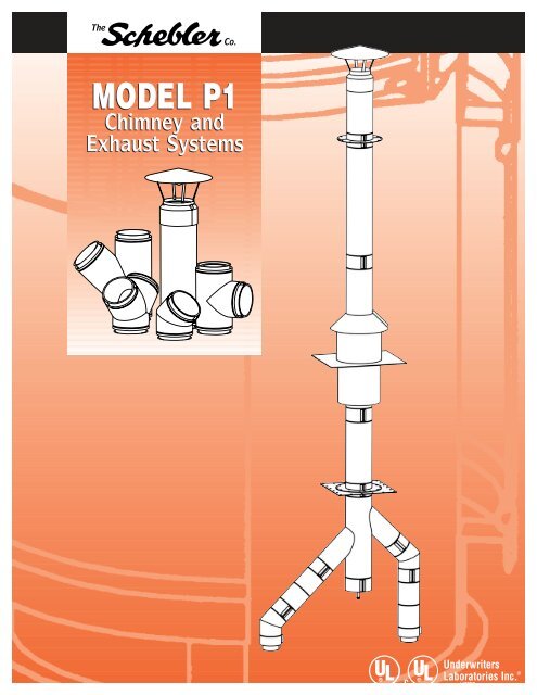
MODEL <strong>P1</strong>Chimney andExhaust SystemsULUL ®Underwriters®cLaboratories Inc. ®LISTED
LISTINGSThe Schebler Model <strong>P1</strong> chimney and exhaust system is listed byUnderwriters Laboratories Inc. (UL) under file number MH17739 foruse as a 1400°F Chimney, a 1000°F Building Heating ApplianceChimney for positive pressures to 60"WC and for Grease Duct. It alsohas the Underwriters Laboratories Mark for Canada (cUL).The system is also approved by the New York City Department ofBuildings for use in New York City. MEA # 227-94-M.SYSTEM CONCEPTThe Model <strong>P1</strong> is a modular double wall prefabricated exhaust systemwith 1" insulation for use in venting appliances that require a positive,neutral or negative draft exhaust system. Sections are provided inlightweight, easy-to-handle lengths. Connections are sealed withpressure tight drawbands and high temperature sealant. Straightsections, expansion joints, tees, elbows and support devices areoffered, allowing a complete exhaust system to be assembled fromstandard components.SURROUNDINGSThe Model <strong>P1</strong> Chimneys are suitable for use with Building HeatingAppliances and other low heat appliances as described in the ChimneySelection chart of the National Fire Protection Association StandardNumber 211 which produce flue exhaust gases not exceeding 1400°Funder continuous operation or 1800°F intermittent operation. Thesechimneys are to be installed as required for metal chimneys. They arenot to be enclosed within combustible construction. An unenclosedchimney may be placed adjacent to walls of combustible constructionat the clearances specified.COMPLETE LINE OF FITTINGS ANDSIZES AVAILABLEThe Model <strong>P1</strong> chimney system is available in even and odd diametersranging from 5" to 48". A complete line of Straight Sections, ExpansionJoints, Tee’s, Elbows, Rain Caps, Roof Penetration components andsupport members are offered. In addition to the standard componentsvirtually any conceivable fitting is available as a special order item.MATERIALS AVAILABLEThe Model <strong>P1</strong> is available in a variety of materials allowing the propermaterial selection for your specific application. The standard productfeatures a 304 stainless steel liner and an aluminized steel outer shell.For greater corrosion resistance 316 stainless steel is available for theliner and 304 or 316 stainless steel for the outer shell.For most applications the standard 304SS inner, aluminized outermaterial selection is sufficient. Under the following conditions you mayconsider the use of alternate materials:• <strong>Boiler</strong>s firing oils heavier than #2 use 316SS for the inner shell.• Exterior installations which are not easily accessible for periodicpainting you should consider a 304SS outer shell which will requireno maintenance.MATERIAL THICKNESSThe standard material thickness for liners is 20 ga. (.035”); for shells itis 22 ga. (.034”). Fittings larger than 24” diameter utilize 18 ga.(.048”) on the shell. Pipe diameters larger than 36” utilize 18 ga. onthe liners and the shells.TESTS PERFORMEDThe Model <strong>P1</strong> has endured rigorous tests by Underwriters Laboratories.Just a few of the tests performed are:• Structural Tests The support plates and wall supports have beenphysically tested to carry a load 4 times that allowed by our listing.• Wind Load Tests Loads equivalent to 110 mph wind have beenapplied to the chimney with acceptable results.• Skin Temperature Rise Tests The chimney has been subjected to aseries of burn tests at temperatures up to 1800°F. The purpose ofthese tests is to determine safe clearances from the chimney wall tocombustible materials.• Rain Tests The rain caps have been tested to ensure that anunsatisfactory amount of water does not enter the rain cap.UNIQUE FEATURESThe Model <strong>P1</strong> offers some unique features that no other chimneymanufacturer can provide.• All of our liners and shells are continuously seam welded. We do notuse spot welds on any of our seams. This assures a leak proof jointand maximum strength. This also minimizes corrosion, addinglongevity to the stack.• Our pipe sections utilize a stiffening bead on the liners. This beadmaintains concentricity of the pipe and prevents the insulation fromsettling in shipment and in operation.• We do not use captive nuts and bolts. If you have ever installed asystem that uses these types of bolts you know how difficult it can beto align and get a nut started on a bolt. Also you do not scrap aband if a nut gets stripped or damaged. All hardware can be easilylocated at your local hardware store in case of emergency.• Our boiler adapters include a seal ring to cover the gap between theliner and shell. The seal ring will provide a neat and completedappearance as well as preventing rodents and birds from entering thearea between the shells and possibly causing damage to theinsulation.SUPPORT LIMITSSupport plates and Wall supports are utilized to support the weight ofthe chimney and to provide a fixed point to allow proper operation ofexpansion joints. In horizontal runs supports should be placed adjacentto fittings that are not otherwise supported. See the individual partdescription for allowable support charts.2
OPERATING TEMPERATURES ANDCLEARANCES CHARTThe model <strong>P1</strong> has been tested and listed for continuous use at both1000° F and 1400° F as well as for use as Grease Duct at the followingclearances to combustible materials. The clearance shown is from theshell to combustibles.<strong>P1</strong> Clearance to CombustiblesSection Inside 1000˚F (560˚C) 1400˚F (760˚C) GreaseDiameter Chimney* Chimney Duct6" 1" (152mm) 1" (178mm) 4" (102mm)8" 1" (178mm) 1" (203mm) 6" (152mm)10" 1" (178mm) 1" (203mm) 6" (152mm)12" 1" (178mm) 1" (203mm) 6" (152mm)14" 1" (203mm) 1" (229mm) 7" (178mm)16" 2" (203mm) 2" (229mm) 7" (178mm)18" 2" (229mm) 2" (254mm) 8" (203mm)20" 2" (229mm) 2" (254mm) 8" (203mm)22" 3" (254mm) 3" (279mm) 9" (229mm)24" 3" (254mm) 3" (279mm) 9" (229mm)26" 4" (279mm) 4" (305mm) 10" (254mm)28" 4" (279mm) 4" (305mm) 10" (254mm)30" 5" (305mm) 5" (330mm) 10" (254mm)32" 5" (305mm) 5" (330mm) 11" (279mm)34" 6" (330mm) 6" (356mm) 11" (279mm)36" 6" (330mm) 6" (356mm) 11" (279mm)38" 7" (356mm) 7" (381mm) 11" (279mm)40" 7" (356mm) 7" (381mm) 11" (279mm)42" 8" (381mm) 8" (406mm) 11" (279mm)44" 8" (381mm) 8" (406mm) 11" (279mm)46" 9" (457mm) 9" (518mm) 11" (279mm)48" 9" (457mm) 9" (518mm) 11" (279mm)*Building Heating Appliance ChimneyClearance to non-combustible materials for all diameters andapplications is 1" (25mm).PART NUMBERSAll standard parts manufactured by Schebler are identified by a partnumber which describes their make up and function.The part numbers are made up as follows1. The first series is the model designation, <strong>P1</strong>, <strong>P1</strong>, P2, P2A, P4, or SW.2. This is followed by the part name. For example 47S, 90T, and CC.3. Next is the part’s internal diameter in inches, such as 06, 12, 24.4. Last is the liner/shell material designation.CODELINER/SHELL MATERIALA304/AluminizedB316/AluminizedC 304/304 or all 304D 316/304E 316/316 or all 316FGalvanizedGAluminizedHPainted Carbon SteelFor example the part number for an 8" ID, Model <strong>P1</strong>, 47" longstraight section with a 304 stainless steel liner and aluminized steelshell is: <strong>P1</strong>47S08A.JOINT ASSEMBLY1. Apply a continuous 1 ⁄4" bead of the proper sealant to one of the flangesbeing joined.2. Fill the “V” in the inner band with the proper sealant.3. Join the two flanged ends of the sections.4. Install the inner band around the flanges and tighten the screws.5. Install the provided insulation strip over the inner band.6. Place the outer band over the space between the shells of the adjoiningsections and tighten the screws. NOTE: For outdoor installations,apply a bead of S600 sealant in the groove at the upper end of theouter band.SEALANTSchebler offers three types of sealant, S600, S2000, andS2001. The S600 is used for applications with flue gastemperatures up to 600°F (315˚C). This includes most boilersand water heaters. The S2000 is used for grease duct systems.S2001 is used for installations operating under positivepressure, such as generator exhaust.STEP 1 STEP 2 STEP 3STEP 4 STEP 5 STEP 63
SYSTEM COMPONENTSCUSTOM DIMENSIONS ARE AVAILABLE TO SUIT YOUR NEEDS IN EVEN AND ODD SIZESADAPTER KIT(FLANGED)Part No. BKFThe Adapter Kit Flanged is usedfor securing pipe to a flangedappliance outlet. Beam clampsare provided for connection ofthe flanges or the flange canbe drilled in the field tomatch the appliance.Includes 1 inner band and 1 sealring to cover the gap betweenthe inner and outer shells.ADAPTER KIT (RAW)Part No. BKRThe Adapter Kit Raw is usedfor securing pipe to anunflanged appliance outlet.Includes 1 inner band and1 seal ring to cover the gapbetween the inner and outershells.STRAIGHT SECTIONPart No. 18S, 29S, 47S,and 59SStandard lengths are asfollows:Diameter 6" is 18", 29" and47"Diameter 8"-24" is 18", 29",47" and 59Diameter 26"-48" is 18", 29"and 47"Custom parts can be manufacturedto any length over 8".ADJUSTABLELENGTHPart No. 18AL, 22AL,30AL, and 45ALThe Adjustable Length isused to provide adjustmentduring installation as well ascompensate for thermalexpansion between fixedpoints.The adjustment in lengthavailable for each part is asfollows:Includes 1 inner and 1 outerband.18AL = 14" to 17"22AL = 16" to 21"30AL = 20" to 29"45AL = 27 1 ⁄2" to 44"Includes 1 inner and1 outer band.Part No. BKFI.D. CLAMPS6" 38" 410" 512" 614" 716" 818" 920" 1022" 1124" 1226" 1328" 1430" 1532" 1634" 1736" 1838" 1940" 2042" 2144" 2246" 2348" 24Part No. BKRI.D.6"8"10"12"14"16"18"20"22"2426"28"30"32"34"36"38"40"42"44"46"48"Part No. 18S/29S/47S/59SI.D.O.D.6" 8"8" 10"10" 12"12" 14"14" 16"16" 18"18" 20"20" 22"22" 24"24" 26"26" 28"28" 30"30" 32"32" 34"34" 36"36" 38"38" 40"40" 42"42" 44"44" 46"46" 48"48" 50"Part No. 18AL/22AL/30AL/45ALI.D.O.D.6" 8"8" 10"10" 12"12" 14"14" 16"16" 18"18" 20"20" 22"22" 24"24" 26"26" 28"28" 30"30" 32"32" 34"34" 36"36" 38"38" 40"40" 42"42" 44"44" 46"46" 48"48" 50"4
VARIABLE LENGTHSECTIONPart No. 18VS, 29VS,VSThe Variable Section adjuststo provide a fixed oddlength between 2 sections.The minimum length is 5",the maximum is 18", 29", or40". This part does notprovide for thermalexpansion.Includes liner, shell, slip joint,and 1 inner band.Part No. 18VS/29VS/VSI.D.O.D.6" 8"8" 10"10" 12"12" 14"14" 16"16" 18"18" 20"20" 22"22" 24"24" 26"26" 28"28" 30"30" 32"32" 34"34" 36"36" 38"38" 40"40" 42"42" 44"44" 46"46" 48"48" 50"BELLOWS SECTIONPart No. BSThe Bellows Section is offeredas an option to the AdjustableLength. This part is recommendedfor diesel engine andturbine exhaust systems.Compensates for 3" of thermalexpansion.Includes liner, shell, and1 inner band.Part No. BSI.D.O.D.6" 8"8" 10"10" 12"12" 14"14" 16"16" 18"18" 20"20" 22"22" 24"24" 26"26" 28"28" 30"30" 32"32" 34"34" 36"36" 38"38" 40"40" 42"42" 44"44" 46"46" 48"48" 50"TAPERED INCREASERPart No. TIThe Tapered Increaser is usedwhen a change in pipe diameteris required.Includes 1 inner and 1 outer bandof both smaller and larger size.Part No. TII.D. A B A B A B A B6" 8" 15" 10" 18" 12" 21" 14" 24"8" 10" 15" 12" 18" 14" 21" 16" 24"10" 12" 15" 14" 18" 16" 21" 18" 24"12" 14" 15" 16" 18" 18" 21" 20" 24"14" 16" 15" 18" 18" 20" 21" 22" 24"16" 18" 15" 20" 18" 22" 21" 24" 24"18" 20" 15" 22" 18" 24" 21" 26" 24"20" 22" 15" 24" 18" 26" 21" 28" 24"22" 24" 15" 26" 18" 28" 21" 30" 24"24" 26" 15" 28" 18" 30" 21" 32" 24"26" 28" 15" 30" 18" 32" 21" 34" 24"28" 30" 15" 32" 18" 34" 21" 36" 24"30" 32" 15" 34" 18" 36" 21" 38" 24"32" 34" 15" 36" 18" 38" 21" 40" 24"34" 36" 15" 38" 18" 40" 21" 42" 24"36" 38" 15" 40" 18" 42" 21" 44" 24"38" 40" 15" 42" 18" 44" 21" 46" 24"40" 42" 15" 44" 18" 46" 21" 48" 24"42" 44" 15" 46" 18" 48" 21" ~ ~44" 46" 15" 48" 18" ~ ~ ~ ~46" 48" 15" ~ ~ ~ ~ ~ ~48" ~ ~ ~ ~ ~ ~ ~ ~*Any size diameter change is possible.**Call for height if not shown.ABRUPT INCREASERPart No. AIThe Abrupt Increaser is used to connect2 sections of different diameters in ashorter space than a Tapered Increaser.Includes 1 inner band of larger andsmaller sizes and 1 seal ring.5
SYSTEM COMPONENTSCUSTOM DIMENSIONS ARE AVAILABLE TO SUIT YOUR NEEDS IN EVEN AND ODD SIZES90˚ TEEPart No. 90TThe 90˚ Tee is used to joinhorizontal and verticalsections, as well as toprovide for connection ofdrain or inspection fittings.Use either the Drain Tee Capor the End Cap for closureof the unused opening.Includes 2 inner bands and2 outer bands.Note: Grease Tees available1 1 ⁄2" containment dam locatedat one opening.REDUCING 90˚ TEEPart No. R90TThe Reducing 90° Tee is usedto join horizontal and verticalsections of different sizes, aswell as provide forconnection to drain orinspection fittings. Use eitherthe Drain Tee Cap or the EndCap for closure of the unusedopening. Specify size ofbranch required.Includes 1 each inner bandand outer band for largerand smaller opening.45˚ LATERAL TEEPart No. 45LTThe 45˚ Lateral Tee is used forlow flow resistance entry intoa stack or breeching.Includes 2 inner bands and2 outer bands.Note: Grease Tees available1 1 ⁄2" containment dam locatedat one opening.REDUCING45˚ LATERAL TEEPart No. R45LTThe Reducing 45° Lateral Teeis used for low flow resistanceentry into a stack or breechingwhen the stack or breeching isa larger size. Specify size ofbranch required.Includes 1 each inner bandand outer band for larger andsmaller opening.Part No. 45LTPart No. 90TI.D.A6" 10 1 ⁄2"8" 11 1 ⁄2"10" 12 1 ⁄2"12" 13 1 ⁄2"14" 14 1 ⁄2"16" 15 1 ⁄2"18" 16 1 ⁄2"20" 17 1 ⁄2"22" 18 1 ⁄2"24" 19 1 ⁄2"26" 20 1 ⁄2"28" 21 1 ⁄2"30" 22 1 ⁄2"32" 23 1 ⁄2"34" 24 1 ⁄2"36" 25 1 ⁄2"38" 26 1 ⁄2"40" 27 1 ⁄2"42" 28 1 ⁄2"44" 29 1 ⁄2"46" 30 1 ⁄2"48" 31 1 ⁄2"Part No. R90TI.D.A6" 10 1 ⁄2"8" 11 1 ⁄2"10" 12 1 ⁄2"12" 13 1 ⁄2"14" 14 1 ⁄2"16" 15 1 ⁄2"18" 16 1 ⁄2"20" 17 1 ⁄2"22" 18 1 ⁄2"24" 19 1 ⁄2"26" 20 1 ⁄2"28" 21 1 ⁄2"30" 22 1 ⁄2"32" 23 1 ⁄2"34" 24 1 ⁄2"36" 25 1 ⁄2"38" 26 1 ⁄2"40" 27 1 ⁄2"42" 28 1 ⁄2"44" 29 1 ⁄2"46" 30 1 ⁄2"48" 31 1 ⁄2"I.D. A B C6" 7" 26" 19"8" 7 3 ⁄8" 28 3 ⁄4" 21 3 ⁄8"10" 7 3 ⁄4" 31 1 ⁄2" 23 3 ⁄4"12" 8 1 ⁄4" 34 1 ⁄2" 26 1 ⁄4"14" 8 5 ⁄8" 37 1 ⁄4" 28 5 ⁄8"16" 9 1 ⁄16" 40 1 ⁄8" 31 1 ⁄16"18" 9 1 ⁄2" 43" 33 1 ⁄2"20" 9 7 ⁄8" 45 3 ⁄4" 35 7 ⁄8"22" 10 5 ⁄16" 48 5 ⁄8" 38 5 ⁄16"24" 10 3 ⁄4" 51 1 ⁄2" 40 3 ⁄4"26" 11 1 ⁄8" 54 1 ⁄4" 43 1 ⁄8"28" 11 9 ⁄16" 57 1 ⁄8" 45 9 ⁄16"30" 12" 60" 48"32" 12 3 ⁄8" 62 3 ⁄4" 50 3 ⁄8"34" 12 3 ⁄4" 65 1 ⁄2" 52 3 ⁄4"36" 13 3 ⁄16" 68 3 ⁄8" 55 3 ⁄16"38" 13 5 ⁄8" 71 1 ⁄4" 57 5 ⁄8"40" 14" 74" 60"42" 14 7 ⁄16" 76 7 ⁄8" 62 7 ⁄16"44" 14 7 ⁄8" 79 3 ⁄4" 64 7 ⁄8"46" 15 1 ⁄4" 82 1 ⁄2" 67 1 ⁄4"48" 15 11 ⁄16" 85 3 ⁄8" 69 11 ⁄16"Part No. R45LTI.D. A B C6" 7" 26" 19"8" 7 3 ⁄8" 28 3 ⁄4" 21 3 ⁄8"10" 7 3 ⁄4" 31 1 ⁄2" 23 3 ⁄4"12" 8 1 ⁄4" 34 1 ⁄2" 26 1 ⁄4"14" 8 5 ⁄8" 37 1 ⁄4" 28 5 ⁄8"16" 9 1 ⁄16" 40 1 ⁄8" 31 1 ⁄16"18" 9 1 ⁄2" 43" 33 1 ⁄2"20" 9 7 ⁄8" 45 3 ⁄4" 35 7 ⁄8"22" 10 5 ⁄16" 48 5 ⁄8" 38 5 ⁄16"24" 10 3 ⁄4" 51 1 ⁄2" 40 3 ⁄4"26" 11 1 ⁄8" 54 1 ⁄4" 43 1 ⁄8"28" 11 9 ⁄16" 57 1 ⁄8" 45 9 ⁄16"30" 12" 60" 48"32" 12 3 ⁄8" 62 3 ⁄4" 50 3 ⁄8"34" 12 3 ⁄4" 65 1 ⁄2" 52 3 ⁄4"36" 13 3 ⁄16" 68 3 ⁄8" 55 3 ⁄16"38" 13 5 ⁄8" 71 1 ⁄4" 57 5 ⁄8"40" 14" 74" 60"42" 14 7 ⁄16" 76 7 ⁄8" 62 7 ⁄16"44" 14 7 ⁄8" 79 3 ⁄4" 64 7 ⁄8"46" 15 1 ⁄4" 82 1 ⁄2" 67 1 ⁄4"48" 15 11 ⁄16" 85 3 ⁄8" 69 11 ⁄16"6
90˚ BOOT TEEPart No. BTThe 90˚ Boot Tee is used tojoin horizontal and verticalsections with lower resistanceas well as to provide forconnection of drain orinspection fittings. Use eitherthe Drain Tee Cap or the EndCap for closure of the unusedopening.Includes 2 inner bands and2 outer bands.90˚ WYEPart No. 90YThe 90˚ Wye is used forjoining runs where low flowresistance is desired.All openings must be thesame size. For connectionto smaller diameter sectionsuse the Tapered or AbruptIncreasers.Includes 2 inner bands and2 outer bands.Note: Grease Wye available1 1 ⁄2" containment dam locatedat one opening.END CAPPart No. ECThe End Cap is used to closean unused tee opening andto provide a means ofaccessing the interior of thesystem for inspection andcleaning.Includes 1 inner band.DRAIN TEE CAPPart No. DTCThe Drain Tee Cap is used toclose an unused tee openingand to provide a drain at thebase of a vertical chimney.Includes 1 inner band.Part No. BTI.D.A6" 10 1 ⁄2"8" 11 1 ⁄2"10" 12 1 ⁄2"12" 13 1 ⁄2"14" 14 1 ⁄2"16" 15 1 ⁄2"18" 16 1 ⁄2"20" 17 1 ⁄2"22" 18 1 ⁄2"24" 19 1 ⁄2"26" 20 1 ⁄2"28" 21 1 ⁄2"30" 22 1 ⁄2"32" 23 1 ⁄2"34" 24 1 ⁄2"36" 25 1 ⁄2"38" 26 1 ⁄2"40" 27 1 ⁄2"42" 28 1 ⁄2"44" 29 1 ⁄2"46" 30 1 ⁄2"48" 31 1 ⁄2"Part No. 90YI.D. A B6" 10 1 ⁄2" 7"8" 11 1 ⁄2" 7 13 ⁄32"10" 12 1 ⁄2" 7 13 ⁄16"12" 13 1 ⁄2" 8 7 ⁄32"14" 14 1 ⁄2" 8 5 ⁄8"16" 15 1 ⁄2" 9 1 ⁄16"18" 16 1 ⁄2" 9 7 ⁄16"20" 17 1 ⁄2" 9 7 ⁄8"22" 18 1 ⁄2" 10 9 ⁄32"24" 19 1 ⁄2" 10 23 ⁄32"26" 20 1 ⁄2" 11 1 ⁄8"28" 21 1 ⁄2" 11 17 ⁄32"30" 22 1 ⁄2" 11 31 ⁄32"32" 23 1 ⁄2" 12 3 ⁄8"34" 24 1 ⁄2" 12 25 ⁄32"36" 25 1 ⁄2" 13 3 ⁄16"38" 26 1 ⁄2" 13 11 ⁄16"40" 27 1 ⁄2" 14 1 ⁄32"42" 28 1 ⁄2" 14 15 ⁄32"44" 29 1 ⁄2" 14 27 ⁄32"46" 30 1 ⁄2" 15 1 ⁄4"48" 31 1 ⁄2" 15 11 ⁄16"Part No. ECI.D.O.D.6" 8"8" 10"10" 12"12" 14"14" 16"16" 18"18" 20"20" 22"22" 24"24" 26"26" 28"28" 30"30" 32"32" 34"34" 36"36" 38"38" 40"40" 42"42" 44"44" 46"46" 48"48" 50"Part No. DTCI.D.O.D.6" 8"8" 10"10" 12"12" 14"14" 16"16" 18"18" 20"20" 22"22" 24"24" 26"26" 28"28" 30"30" 32"32" 34"34" 36"36" 38"38" 40"40" 42"42" 44"44" 46"46" 48"48" 50"7
SYSTEM COMPONENTSCUSTOM DIMENSIONS ARE AVAILABLE TO SUIT YOUR NEEDS IN EVEN AND ODD SIZES90° ELBOWPart No. 90LThe 90° Elbow is used whenmaking a 90° directionalchange. The 90° Elbow isavailable in sizes 6" through24". For a 90° directionalchange in diameters from 26"through 48" use two 45°Elbows.Includes 1 inner band and1 outer band.45° ELBOWPart No. 45LThe 45° Elbow is usedwhen a vertical or horizontaldirection change of 45°is desired.Includes 1 inner band and1 outer band.30° ELBOWPart No. 30LThe 30° Elbow is usedwhen a vertical or horizontaldirection change of 30°is desired.Includes 1 inner band and1 outer band.Part No. 90LI.D.A6" 13 1 ⁄2"8" 15 1 ⁄2"10" 17 1 ⁄2"12" 19 1 ⁄2"14" 21 1 ⁄2"16" 23 1 ⁄2"18" 25 1 ⁄2"20" 27 1 ⁄2"22" 29 1 ⁄2"24" 31 1 ⁄2"Part No. 45LID A B C D6" 7" 9 29 ⁄32" 23 29 ⁄32" 16 29 ⁄32"8" 7 3 ⁄8" 10 7 ⁄16" 25 3 ⁄16" 17 13 ⁄16"10" 7 3 ⁄16" 11 3 ⁄64" 26 43 ⁄64" 18 55 ⁄64"12" 8 1 ⁄4" 11 43 ⁄64" 28 11 ⁄64" 19 59 ⁄64"14" 8 5 ⁄8" 12 13 ⁄64" 29 29 ⁄64" 20 53 ⁄64"16" 9 1 ⁄16" 1 13 ⁄16" 30 15 ⁄16" 21 7 ⁄8"18" 9 1 ⁄2" 13 7 ⁄16" 32 7 ⁄16" 22 15 ⁄16"20" 9 7 ⁄8" 13 31 ⁄32" 33 23 ⁄32" 23 27 ⁄32"22" 10 5 ⁄16" 14 37 ⁄64" 35 13 ⁄64" 24 57 ⁄64"24" 10 3 ⁄4" 15 13 ⁄64" 36 45 ⁄64" 25 61 ⁄64"26" 11 1 ⁄8" 15 47 ⁄64" 37 63 ⁄64" 26 55 ⁄64"28" 11 9 ⁄16" 16 23 ⁄64" 39 31 ⁄64" 27 59 ⁄64"30" 11 15 ⁄16" 16 7 ⁄8" 40 3 ⁄4" 28 13 ⁄16"32" 12 3 ⁄8" 17 1 ⁄2" 42 1 ⁄4" 29 7 ⁄8"34" 12 3 ⁄4" 18 1 ⁄32" 43 17 ⁄32" 30 25 ⁄32"36" 13 3 ⁄16" 18 21 ⁄32" 45 1 ⁄32" 31 27 ⁄32"38" 13 5 ⁄8" 19 17 ⁄64" 46 33 ⁄64" 32 57 ⁄64"40" 14" 19 51 ⁄64" 47 51 ⁄64" 33 51 ⁄64"42" 14 7 ⁄16" 20 27 ⁄64" 49 19 ⁄64" 34 55 ⁄64"44" 14 7 ⁄8" 21 1 ⁄32" 50 25 ⁄32" 35 29 ⁄64"46" 15 1 ⁄4" 21 9 ⁄16" 52 1 ⁄16" 36 13 ⁄16"48" 15 11 ⁄16" 22 3 ⁄16" 53 9 ⁄16" 37 7 ⁄8"8Part No. 30LID A B C D6" 6 1 ⁄8" 6 1 ⁄8" 22 55 ⁄64" 13 13 ⁄64"8" 6 3 ⁄8" 6 3 ⁄8" 23 51 ⁄64" 13 47 ⁄34"10" 6 5 ⁄8" 6 5 ⁄8" 24 23 ⁄32" 14 9 ⁄32"12" 6 15 ⁄16" 6 15 ⁄16" 25 57 ⁄64" 14 61 ⁄64"14" 7 3 ⁄16" 7 3 ⁄16" 26 53 ⁄64" 15 31 ⁄64"16" 7 7 ⁄16" 7 7 ⁄16" 27 3 ⁄4" 16 1 ⁄32"18" 7 3 ⁄4" 7 3 ⁄4" 28 59 ⁄64" 16 45 ⁄64"20" 8" 8" 29 55 ⁄64" 17 15 ⁄6422" 8 1 ⁄4" 8 1 ⁄4" 30 51 ⁄64" 17 23 ⁄32"24" 8 1 ⁄2" 8 1 ⁄2" 31 23 ⁄32" 18 5 ⁄16"26" 8 3 ⁄4" 8 3 ⁄4" 32 21 ⁄32" 18 55 ⁄64"28" 9 1 ⁄16" 9 1 ⁄16" 33 53 ⁄64" 19 17 ⁄32"30" 9 5 ⁄16" 9 5 ⁄16" 34 3 ⁄4" 20 1 ⁄16"32" 9 9 ⁄16" 9 9 ⁄16" 35 11 ⁄16" 20 39 ⁄64"34" 9 7 ⁄8" 9 7 ⁄8" 36 55 ⁄64" 21 9 ⁄32"36" 10 1 ⁄8" 10 1 ⁄8" 37 25 ⁄32" 21 13 ⁄16"38" 10 3 ⁄8" 10 3 ⁄8" 38 23 ⁄32" 22 23 ⁄64"40" 10 5 ⁄8" 10 5 ⁄8" 39 21 ⁄32" 22 57 ⁄64"42" 10 15 ⁄16" 10 15 ⁄16" 40 13 ⁄16" 23 9 ⁄16"44" 11 3 ⁄16" 11 3 ⁄16" 41 3 ⁄4" 24 7 ⁄64"46" 11 1 ⁄2" 11 1 ⁄2" 42 59 ⁄64" 24 25 ⁄32"48" 11 3 ⁄4" 11 3 ⁄4" 43 55 ⁄64" 25 5 ⁄16"
DRAIN SECTIONPart No. DSThe Drain Section is used todrain rain water andcondensation from within thestack. The NPT nipple shouldbe connected to a suitabledrain.Includes 1 inner band and1 outer band.HORIZONTAL DRAINPart No. HDThe Horizontal Drain is usedto attach grease traps anddrain pipes to grease duct.Includes 1 inner band and1 outer band.NOZZLE SECTIONPart No. NSThe Nozzle Section is used toattach plumbing equipmentto grease ducts.Includes 1 inner band and1 outer band.BASE DRAINSECTIONPart No. BDThe Base Drain Sectionprovides a bottom closureand drain attachment forbase supported chimneys.Includes 1 inner band and1 outer band.Part No. NSI.D.O.D.6" 8"8" 10"Part No. DSI.D.O.D.6" 8"8" 10"10" 12"12" 14"14" 16"16" 18"18" 20"20" 22"22" 24"24" 26"26" 28"28" 30"30" 32"32" 34"34" 36"36" 38"38" 40"40" 42"42" 44"44" 46"46" 48"48" 50"Part No. HDI.D.O.D.6" 8"8" 10"10" 12"12" 14"14" 16"16" 18"18" 20"20" 22"22" 24"24" 26"26" 28"28" 30"30" 32"32" 34"34" 36"36" 38"38" 40"40" 42"42" 44"44" 46"46" 48"48" 50"10" 12"12" 14"14" 16"16" 18"18" 20"20" 22"22" 24"24" 26"26" 28"28" 30"30" 32"32" 34"34" 36"36" 38"38" 40"40" 42"42" 44"44" 46"46" 48"48" 50"Part No. BDI.D.O.D.6" 8"8" 10"10" 12"12" 14"14" 16"16" 18"18" 20"20" 22"22" 24"24" 26"26" 28"28" 30"30" 32"32" 34"34" 36"36" 38"38" 40"40" 42"42" 44"44" 46"46" 48"48" 50"9
SYSTEM COMPONENTSCUSTOM DIMENSIONS ARE AVAILABLE TO SUIT YOUR NEEDS IN EVEN AND ODD SIZESFLASHINGPart No. FLThe Flashing is used inconjunction with the RainCollar to seal roofpenetrations. This part isdesigned for flat roofs.Custom Pitched Flashings areavailable upon request.RAIN COLLARPart No. RCThe Rain Collar is used inconjunction with the Flashingto seal roof penetrations.INSULATED THIMBLEPart No. ITThe Insulated Thimble is usedwhen penetrating acombustible wall or roof. Thispart is designed for flat roofs.Custom Pitched Thimbles areavailable upon request.RAIN CAPPart No. CCThe Rain Cap is used at stackterminations to prevent waterfrom entering the flue. A drainshould be used at the baseof stacks to drain off waterthat may be blown into flue.Includes 1 inner band and1 closure ring to seal outershell joint.Part No. RCPart No. FLI.D. A B6" 15 1 ⁄8" 23 1 ⁄8"8" 17" 25"10" 19" 27"12" 21" 29"14" 23" 31"16" 25" 33"18" 27" 35"20" 29" 37"22" 31" 39"24" 33" 41"26" 35" 43"28" 37" 45"30" 39" 47"32" 41" 49"34" 43" 51"36" 45" 53"38" 47" 55"40" 49" 57"42" 51" 59"44" 53" 61"46" 55" 63"48" 57" 65"I.D.A6" 8 3 ⁄16"8" 10 1 ⁄16"10" 12 1 ⁄16"12" 14 1 ⁄16"14" 16 1 ⁄16"16" 18 1 ⁄16"18" 20 1 ⁄16"20" 22 1 ⁄16"22" 24 1 ⁄16"24" 26 1 ⁄16"26" 28 1 ⁄16"28" 30 1 ⁄16"30" 32 1 ⁄16"32" 34 1 ⁄16"34" 36 1 ⁄16"36" 38 1 ⁄16"38" 40 1 ⁄16"40" 42 1 ⁄16"42" 44 1 ⁄16"44" 46 1 ⁄16"46" 48 1 ⁄16"48" 50 1 ⁄16"Part No. ITI.D.A6" 10"8" 12"10" 14"12" 16"14" 18"16" 20"18" 22"20" 24"22" 26"24" 28"26" 30"28" 32"30" 34"32" 36"34" 38"36" 40"38" 42"40" 44"42" 46"44" 48"46" 50"48" 52"Part No. CCI.D. A B6" 20" 4 1 ⁄2"8" 22" 6"10" 24" 7 1 ⁄2"12" 26" 9"14" 28" 10 1 ⁄2"16" 30" 12"18" 32" 13 1 ⁄2"20" 34" 15"22" 36" 16 1 ⁄2"24" 38" 18"26" 40" 19 1 ⁄2"28" 42" 21"30" 44" 22 1 ⁄2"32" 49" 24"34" 52" 25 1 ⁄2"36" 55" 27"38" 58" 28 1 ⁄2"40" 61" 30"42" 64" 32 1 ⁄2"44" 67" 33"46" 70" 34 1 ⁄2"48" 72" 36"10
TOP SECTIONEXIT CONEFLIP TOP CAPPart No. FTCFAN ADAPTERPart No. TSPart No. EXCPart No. FAThe Top Section is used toprotect the insulating spacebetween the inner and outershells when an opentermination is required.A drain should be used atthe base of stacks to drainoff water that enters thesystem.Includes 1 inner band and1 closure ring to seal outershell joint.The Exit Cone is used toincrease the flue gas velocityexiting the stack. A drainshould be used at the base ofstacks to remove any waterthat enters the stack.Includes 1 inner band and1 closure ring to seal outershell joint.The Flip Top Cap is used ingenerator systems when thecap remains closed untilpressure opens the cap.Includes 1 inner band and1 closure ring to seal outershell joint.The Fan Adapter is used toattach grease duct to anexhaust fan or kitchen hood.Includes 1 inner band and1 outer band.Note: Plenum boxes availablefor multiple fan systems.Part No. TSI.D.O.D.6" 8"8" 10"10" 12"12" 14"14" 16"16" 18"18" 20"20" 22"22" 24"24" 26"26" 28"28" 30"30" 32"32" 34"34" 36"36" 38"38" 40"40" 42"42" 44"44" 46"46" 48"48" 50"Part No. EXCI.D. A B6" 4 7 ⁄8" 5 3 ⁄8"8" 6 1 ⁄2" 6 1 ⁄8"10" 8 1 ⁄8" 6 3 ⁄4"12" 9 3 ⁄4" 7 1 ⁄2"14" 11 3 ⁄8" 8 1 ⁄8"16" 13 1 ⁄8" 8 7 ⁄8"18" 14 3 ⁄4" 9 1 ⁄2"20" 16 3 ⁄8" 10 1 ⁄4"22" 18" 10 7 ⁄8"24" 19 5 ⁄8" 11 5 ⁄8"26" 21 1 ⁄4" 12 1 ⁄4"28" 22 7 ⁄8" 13"30" 24 1 ⁄2" 13 5 ⁄8"32" 26 1 ⁄8" 14 3 ⁄8"34" 27 3 ⁄4" 15"36" 29 3 ⁄8" 15 3 ⁄4"38" 31" 16 3 ⁄8"40" 32 5 ⁄8" 17 1 ⁄8"42" 34 1 ⁄4" 17 3 ⁄4"44" 35 7 ⁄8" 18 1 ⁄2"46" 37 1 ⁄2" 19 1 ⁄8"48" 39 1 ⁄4" 19 3 ⁄4"Part No. FTCI.D.O.D.6" 8"8" 10"10" 12"12" 14"14" 16"16" 18"18" 20"20" 22"22" 24"24" 26"26" 28"28" 30"30" 32"32" 34"34" 36"36" 38"38" 40"40" 42"42" 44"44" 46"46" 48"48" 50"Part No. FAI.D.O.D.6" 8"8" 10"10" 12"12" 14"14" 16"16" 18"18" 20"20" 22"22" 24"24" 26"26" 28"28" 30"30" 32"32" 34"34" 36"36" 38"38" 40"40" 42"42" 44"44" 46"46" 48"48" 50"11
SYSTEM COMPONENTSCUSTOM DIMENSIONS ARE AVAILABLE TO SUIT YOUR NEEDS IN EVEN AND ODD SIZESHORIZONTALTERMINATIONPart No. HTThe Horizontal Termination isused when the stackterminates in a horizontalposition. Birdscreen coversthe opening to prevent anybirds or rodents fromentering.Includes 1 inner band and1 outer band.SUPPORT PLATEPart No. SPThe Support Plate is theprimary load carrying memberof the chimney assembly. Thispart is designed to support(B) (See Chart below) feet ofvertical chimney section aswell as provide fixed pointsin breeching runs.Includes 1 inner band and2 half bands.NOTE: THIS PART MUST BEPLACED AT THE CONNECTIONOF TWO FLUE SECTIONS.WALL SUPPORTPart No. WSThe Wall Support is used toprovide chimney supportalong a wall. The Wall Supportwill maintain the requiredclearance to combustiblestructures when properlyinstalled and can support(C) (See Chart Below) feet ofvertical chimney.Includes 1 inner band and2 half bands.NOTE: THIS PART MUST BEPLACED AT THE CONNECTIONOF TWO FLUE SECTIONS.GUY SECTIONPart No. GSThe Guy Section is to beused when the chimneyextends beyond the verticallimits above the roof line.The Guy Section should beconnected to guy wires or arigid guying structure.Includes 1 inner band and 2half bands.NOTE: THIS PART MUST BEPLACED AT THE CONNECTIONOF TWO FLUE SECTIONS.Part No. HTI.D.A6" 19 9 ⁄16"8" 20 7 ⁄16"10" 21 1 ⁄2"12" 22 1 ⁄2"14" 23 1 ⁄2"16" 24 1 ⁄2"18" 25 1 ⁄2"20" 26 1 ⁄2"22" 27 1 ⁄2"24" 28 1 ⁄2"Part No. SPI.D. A B(FT.)6" 19 3 ⁄16" 270'8" 21 3 ⁄16" 244'10" 23 3 ⁄16" 230'12" 25 3 ⁄16" 213'14" 27 3 ⁄16" 202'16" 29 3 ⁄16" 192'18" 31 3 ⁄16" 180'20" 34 3 ⁄16" 172'22" 36 3 ⁄16" 163'24" 38 3 ⁄16" 155'26" 40 3 ⁄16" 146'28" 42 3 ⁄16" 136'30" 44 3 ⁄16" 128'32" 46 3 ⁄16" 145'34" 48 3 ⁄16" 135'36" 50 3 ⁄16" 103'38" 52 3 ⁄16" 94'40" 54 3 ⁄16" 86'42" 56 3 ⁄16" 78'44" 58 3 ⁄16" 71'46" 60 3 ⁄16" 63'48" 62 3 ⁄16" 56'Part No. WSI.D. A B C(FT.)6" 11" 10 3 ⁄16" 171'8" 13" 12 3 ⁄16" 156'10" 14" 13 1 ⁄2" 147'12" 15" 17 7 ⁄8" 138'14" 17" 16 3 ⁄16" 132'16" 18" 17 1 ⁄2" 127'18" 20" 19 7 ⁄16"" 120'20" 21" 21 1 ⁄8" 116'22" 23" 23 1 ⁄8" 111'24" 24" 24 1 ⁄2" 107'26" 26" 26 7 ⁄16" 103'28" 27" 27 3 ⁄4" 97'30" 29" 29 3 ⁄4" 93'32" 30" 31 1 ⁄8" 108'34" 32" 33 1 ⁄16" 102'36" 33" 34 3 ⁄8" 80'38" 35" 36 7 ⁄16" 75'40" 36" 37 3 ⁄4" 71'42" 38" 41 1 ⁄16" 67'44" 39" 42 3 ⁄8" 63'46" 44" 43 11 ⁄16" 59'48" 45" 45" 56'Part No. GSI.D. A B6" 10 5 ⁄8" 88" 12 5 ⁄8" 810" 15 3 ⁄16" 1212" 17 3 ⁄16" 1214" 19 3 ⁄16" 1216" 21 3 ⁄16" 1218" 23 3 ⁄16" 1220" 25 3 ⁄16" 1222" 27 3 ⁄16" 1224" 30 3 ⁄16" 1226" 32 3 ⁄16" 1228" 34 3 ⁄16" 1630" 36 3 ⁄16" 1632" 38 3 ⁄16" 1634" 40 3 ⁄16" 1636" 42 3 ⁄16" 2038" 44 3 ⁄16" 2040" 46 3 ⁄16" 2042" 48 3 ⁄16" 2044" 50 3 ⁄16" 2446" 52 3 ⁄16" 2448" 54 3 ⁄16" 2812
FULL RINGPart No. FRHALF RINGPart No. HRFLOOR/ROOF GUIDEWALL GUIDEPart No. WGPart No. FRGThe Full Ring is used to guidehorizontal and vertical runs.The part is simply boltedaround the outer shell thenrigidly connected to thebuilding structure.The Half Ring has the samedimensions as the full ring.This Half Ring is used tosupport long horizontal runs.This part would be placedunder the flue and thensupported by rods connectingto the building structure.The Floor/Roof Guide is usedat the penetration of floorsand roofs to guide thechimney. This part isdesigned to absorb lateralloads only. It will not supportvertical chimney sections.The Wall Guide is used toguide long vertical runs thatare placed adjacent to walls.This part will maintain properclearance to combustibleswhen properly installed.Part No. FRGPart No. FRFLUE ID RING ID ANGLE SIZE # HOLES HOLE SIZE B.C.6" 8 1 ⁄8" 1 1 ⁄4"x1 1 ⁄4"x 1 ⁄8" 8 3⁄8" 9 1 ⁄2"8" 10 1 ⁄8" 1 1 ⁄4"x1 1 ⁄4"x 1 ⁄8" 8 3⁄8" 11 1 ⁄2"10" 12 3 ⁄16" 1 1 ⁄2"x1 1 ⁄2"x 1 ⁄8" 12 7⁄16" 13 13 ⁄16"12" 14 3 ⁄16" 1 1 ⁄2"x1 1 ⁄2"x 1 ⁄8" 12 7⁄16" 15 13 ⁄16"14" 16 3 ⁄16" 1 1 ⁄2"x1 1 ⁄2"x 3 ⁄16" 16 7⁄16" 18 1 ⁄8"16" 18 3 ⁄16" 1 1 ⁄2"x1 1 ⁄2"x 3 ⁄16" 16 7⁄16" 20 1 ⁄8"18" 20 3 ⁄16" 1 1 ⁄2"x1 1 ⁄2"x 3 ⁄16" 20 7⁄16" 22 1 ⁄8"20" 22 3 ⁄16" 1 1 ⁄2"x1 1 ⁄2"x 3 ⁄16" 20 7⁄16" 24 1 ⁄8"22" 24 3 ⁄16" 1 1 ⁄2"x1 1 ⁄2"x 3 ⁄16" 20 7⁄16" 26 1 ⁄8"24" 26 3 ⁄16" 2"x2"x 3 ⁄16" 24 7⁄16" 28 1 ⁄2"26" 28 3 ⁄16" 2"x2"x 3 ⁄16" 24 7⁄16" 30 1 ⁄2"28" 30 3 ⁄16" 2"x2"x 3 ⁄16" 28 7⁄16" 32 1 ⁄2"30" 32 3 ⁄16" 2"x2"x 3 ⁄16" 28 7⁄16" 34 1 ⁄2"32" 34 3 ⁄16" 2"x2"x 3 ⁄16" 32 7⁄16" 36 1 ⁄2"34" 36 3 ⁄16" 2"x2"x 3 ⁄16" 32 7⁄16" 38 1 ⁄2"36" 38 3 ⁄16" 2"x2"x 3 ⁄16" 36 7⁄16" 40 1 ⁄2"38" 40 3 ⁄16" 2"x2"x 3 ⁄16" 36 7⁄16" 42 1 ⁄2"40" 42 3 ⁄16" 2"x2"x 3 ⁄16" 40 7⁄16" 44 1 ⁄2"42" 44 3 ⁄16" 2"x2"x 3 ⁄16" 40 7⁄16" 46 1 ⁄2"44" 46 3 ⁄16" 2"x2"x 3 ⁄16" 44 7⁄16" 48 1 ⁄2"46" 48 3 ⁄16" 2"x2"x 3 ⁄16" 44 7⁄16" 50 1 ⁄2"48" 50 3 ⁄16" 2"x2"x 3 ⁄16" 48 7⁄16" 52 1 ⁄2"I.D.A6" 9 3 ⁄8"8" 10 3 ⁄8"10" 11 3 ⁄8"12" 12 3 ⁄8"14" 13 3 ⁄8"16" 14 3 ⁄8"18" 15 3 ⁄8"20" 16 3 ⁄8"22" 17 3 ⁄8"24" 18 3 ⁄8"26" 19 3 ⁄8"28" 20 3 ⁄8"30" 21 3 ⁄8"32" 22 3 ⁄8"34" 23 3 ⁄8"36" 24 3 ⁄8"38" 25 3 ⁄8"40" 26 3 ⁄8"42" 27 3 ⁄8"44" 28 3 ⁄8"46" 29 3 ⁄8"48" 30 3 ⁄8"Part No. WGI.D. A B6" 11" 7 13 ⁄16"8" 13" 8 1 ⁄2"10" 14" 8 5 ⁄8"12" 15" 9"14" 17" 9 7 ⁄16"16" 18" 9 3 ⁄4"18" 20" 10 1 ⁄4"20" 21" 10 9 ⁄16"22" 23" 11 1 ⁄8"24" 24" 11 5 ⁄16"26" 26" 11 7 ⁄8"28" 27" 12 1 ⁄8"30" 29" 12 11 ⁄16"32" 30" 12 15 ⁄16"34" 32" 13 1 ⁄2"36" 33" 13 11 ⁄16"38" 35" 14 5 ⁄16"40" 36" 14 1 ⁄2"42" 38" 15 1 ⁄16"44" 39" 15 5 ⁄16"46" 44" 16 11 ⁄16"48" 45" 16 7 ⁄8"13
SYSTEM COMPONENTSCUSTOM DIMENSIONS ARE AVAILABLE TO SUIT YOUR NEEDS IN EVEN AND ODD SIZESPRESSURE RELIEFVALVEPart No. PRVThe Pressure Relief Valve isused in generator exhaustsystems to prevent damageresulting in the ignition ofunburned fuel. Thiscomponent complies withNF<strong>P1</strong> 37.SQUARE-TO-R0UNDTRANSITIONSThe Square-to-RoundTransitions are used whenconnecting to appliances withsquare or rectangularoutlets. The base can be rawfor field welding or flangedfor field drilling and bolting.Valves are set to 1 PSI.Part No. PRVI.D.A6" 9 1 ⁄8"8" 11"10" 13"12" 15"14" 17"16" 19"18" 21"20" 23"22" 25"COLD-FACE TEMPERATURE500°F400°F300°F200°FOUTER SHELL TEMP CHART100°F0°F350°F 500°F 1000°F 1400°FMID-FLUE TEMPERATURE14
<strong>P1</strong> WEIGHT CHARTPartPart Description Number 6"14" to 17" Adjustable 18AL 13lbs.16" to 21" Adjustable 22AL 15lbs.20" to 29" Adjustable 30AL 19lbs.27 1 ⁄2" to 44" Adjustable 45AL 26lbs.29" Straight Section 29S 17lbs.30 Degree Elbow 30L 9lbs.45 Degree Elbow 45L 19lbs.45 Degree Tee 45LT 23lbs.47" Straight Section 47S 26lbs.59" Straight Section 59S -90 Degree Elbow 90L 14lbs.90 Degree Grease Tee 90GT 19lbs.90 Degree Tee 90T 19lbs.90 Degree Wye 90Y 17lbs.Abrupt Increaser AI 7lbs.Base Drain BD 13lbs.Bellows Section BS 14lbs.<strong>Boiler</strong> Kit Flanged BKF 7lbs.<strong>Boiler</strong> Kits Raw BKR 4lbs.Drain Section DS 12lbs.Drain Tee Cap DTC 5lbs.End Cap EC 4lbs.Fan Adapter FA 11lbs.Flashing FL 11lbs.Floor/Roof Guide FRG 10lbs.Full Ring FR 3lbs.Guy Section GS 9lbs.Half Ring HR 2lbs.Horizontal Drain HD 12lbs.Insulated Thimble IT 20lbs.Nozzle Section NS 12lbs.Rain Cap CC 9lbs.Rain Collar RC 4lbs.Support Plate SP 31lbs.Tapered Increaser TI 14lbs.Top Section TS 3lbs.Variable Section VS 26lbs.Wall Guide WG 14lbs.Wall Support WS 53lbs.Inside Diameter (Inches)8" 10" 12" 14" 16" 18" 20" 22" 24" 26" 28" 30" 32" 34" 36" 38" 40" 42" 44" 46" 48"16 20 23 26 30 33 36 40 43 46 50 53 56 60 75 92 97 101 106 111 11819 23 27 31 34 38 42 46 50 54 58 62 66 69 88 107 113 118 124 129 13524 29 34 39 44 49 54 59 64 69 74 79 84 89 113 138 145 152 159 166 17333 40 48 55 62 69 76 83 90 97 105 112 119 126 162 195 205 215 225 235 24522 27 31 36 40 45 49 54 59 63 68 73 77 82 104 126 133 139 146 152 15911 14 16 19 22 26 29 38 42 47 52 57 62 67 72 91 98 105 112 120 12712 15 19 22 26 30 34 46 52 58 64 71 78 85 92 116 125 135 145 154 16532 41 52 63 76 90 105 146 167 189 213 238 263 290 319 400 435 472 511 551 59333 40 48 55 62 69 76 83 90 97 105 112 119 126 162 195 205 215 225 235 24540 49 59 67 76 85 94 103 111 - - - - - - - - - - - -19 26 33 42 51 61 72 103 119 - - - - - - - - - - - -25 32 39 47 55 64 74 100 113 126 140 155 171 187 204 256 277 299 322 345 36925 31 39 46 55 63 73 99 112 125 139 154 169 186 202 254 275 297 319 342 36622 28 34 41 48 56 64 87 98 109 121 134 148 162 176 222 240 259 278 298 3198 10 12 13 15 17 18 20 22 23 25 27 28 30 32 40 42 44 46 48 5215 18 21 24 27 30 33 36 39 42 45 48 51 54 63 76 80 83 87 91 9518 21 25 28 32 36 39 43 46 50 54 57 61 65 81 100 105 110 115 120 1258 10 12 13 15 17 18 20 22 23 25 27 28 30 32 40 42 44 46 48 525 6 7 8 8 9 10 11 12 13 14 15 15 16 17 25 26 27 29 30 3116 19 22 25 28 32 35 38 41 44 48 51 54 57 72 88 93 97 102 106 1116 7 8 9 11 12 14 16 18 20 22 25 27 30 42 51 55 59 64 69 745 6 7 8 10 11 13 15 17 19 21 24 26 29 41 50 54 58 63 68 7313 16 18 21 23 26 28 31 34 36 39 42 44 47 55 67 70 74 77 81 8512 13 15 16 18 19 21 22 24 25 27 29 30 32 34 35 37 39 40 42 4410 11 12 15 16 17 18 19 24 25 27 27 30 30 32 33 34 35 36 38 394 5 6 9 10 11 12 13 18 19 21 21 24 24 26 27 28 29 30 32 3311 13 14 16 18 20 22 23 25 27 29 31 32 34 36 42 44 46 48 50 522 3 3 5 5 5 6 6 9 10 10 11 12 12 13 13 14 15 15 16 1716 19 22 25 28 32 35 38 41 44 48 51 54 57 72 88 93 97 102 106 11122 25 28 31 33 36 39 42 44 47 50 52 55 58 61 63 66 69 72 74 7716 19 22 25 28 32 35 38 41 44 48 51 54 57 72 88 93 97 102 106 11111 13 16 18 21 24 27 31 34 37 41 45 52 57 65 73 79 86 92 99 1054 5 5 6 6 7 7 8 8 9 9 10 10 11 11 12 12 13 13 14 1436 42 47 53 58 64 70 76 99 107 114 122 130 138 146 186 196 206 217 227 23818 22 26 29 33 37 41 53 58 62 66 71 76 80 84 104 109 114 119 125 1304 5 5 6 7 8 9 9 10 11 12 12 13 14 17 21 22 23 24 25 2633 32 48 55 62 69 76 83 90 97 105 112 119 126 162 195 205 215 225 235 24517 17 21 26 28 31 34 37 44 48 50 53 57 60 62 66 39 73 75 85 8765 65 86 101 113 129 144 162 192 212 229 252 270 294 313 364 386 415 438 476 515All weights shown above are actual weights, for shipping weights multiply by 1.25SAMPLE SPECIFICATION -- MODEL <strong>P1</strong>The factory built modular chimney shall be laboratory tested and listedin accordance with Underwriters Laboratories Standard UL 103 for usewith building heating equipment burning gas, solid or liquid fuels withflue gases not exceeding 1400°F continuous operations and 1800°Fintermittent operation. It shall also be tested and listed for use as aGrease Duct in accordance with UL 1978. Sections shall bear the ULlisting mark and the cUL listing mark for Canada. Sections shall besealed with banded flanges and silicone joint sealant for temperaturesup to 600°F and Grease Duct.Inner shell material shall be type 304 stainless steel for natural gasand number 2 oil fired appliances, type 316 stainless steel for coal,number 4 and number 6 oil fired appliances. Inner shell thickness shallbe .036" for 6" to 36" diameter systems and .048" for 38" to 48"diameter systems. All inner shell seams shall be full penetrationwelded the entire length of the pipe section. Riveted, tack or spotwelded seams are not permitted.Outer shell material shall be aluminized steel with a thickness of .034"for 6" to 36" diameter systems and .052" for 38" to 48" systems.(Outer shell thickness of optional type 304 or 316 stainless steel shallbe .030" for 6" to 36" diameter systems and .048" for 38" to 48"diameter systems). All outer shell seams shall be full penetrationwelded the entire length of the pipe section. Riveted, tack or spotwelded seams are not permitted.Between the inner and outer shells there shall be a minimum 1" of1600°F rated low conductivity ceramic fiber insulation. The insulationis to be securely attached to the inner shell with steel straps andinsulating pins welded to the inner shell. Stainless steel centering clipsshall be welded to the outer shell to maintain the 1" spacing andensure concentricity of the shells.Breeching and chimney sections, when installed according tomanufacturer’s instructions, shall comply with national safety standardsand building codes. Stacks terminating above a roof must terminate asrequired by code or NF<strong>P1</strong> 211.Chimney sections exposed to atmospheric conditions shall be protectedby a minimum of one base coat and one finish coat of heat resistantpaint after installation. Outer shells of type 304 or 316 stainless steelneed not be painted.15
12MODEL <strong>P1</strong> STANDARD 1-YEAR WARRANTYThe Schebler Model <strong>P1</strong> Chimney, where installed according tomanufacturer’s installation instructions, is warranted by theSchebler Company for a period of one (1) year from date ofsystem start-up, against defects in material and workmanshipof the product for parts only. Any defective part in theproduct will, at Schebler’s option, either be repaired orreplaced. Should the part be returned, the owner must payall transportation charges. The repaired or replacement partwill, in turn, be shipped by Schebler to the owner, freightprepaid. The warranty on any repaired or replacement partshall be for a duration of time no longer than the remainingor unexpired term of the original warranty.This warranty does not cover labor or other service chargesincurred by the owner, nor any parts not manufactured byThe Schebler Company, or any other components that arenot part of the Model <strong>P1</strong> Chimney Systems.This limited warranty is extended to the purchaser subject tothe satisfaction of the following conditions:Generally accepted engineering practices have been followedto determine that sizing and material specifications are suitablefor the application and environment involved.The undamaged components have been correctly installed inaccordance with the installation instructions published byThe Schebler Company at the time of shipment.The Schebler Company assumes no liability for incidental orconsequential damages of any kind or for any damagesresulting in whole or part from misuse, improper installation,or inadequate maintenance of the system or component partthereof. This warranty is in lieu of all other express warrantiesor guarantees of any kind. All implied warranties, includingmerchantability and fitness, are limited to the duration of theexpress warranty contained herein. The Schebler Companyneither assumes nor does it authorize any other person toassume on its behalf any other liability in connection with thesale of its products.Inner shell 1/2"rolled flangeOuter shellInner shellInner V-bandwith clipsOuter bandwith clips1" ceramic fiberinsulationModel <strong>P1</strong>spacer clip12345MODEL <strong>P1</strong> EXTENDED 10-YEAR WARRANTYThe Schebler Company warrants owners of its Model <strong>P1</strong>Chimney against defects in material and workmanship innormal use for ten (10) years from the date of delivery to theconstruction site when installed, maintained and used as partof a Schebler Model <strong>P1</strong> Chimney System and in accordancewith The Schebler Company specifications. The ScheblerCompany further warrants any portion of the chimney systemrepaired or replaced under this warranty for the remainder ofthe original warranty period.This warranty is limited to repair or replacement of the productplus shipping cost to the failure location. This warranty doesnot cover any labor costs for removal or replacement of thedefective product nor does this warranty cover any systemcomponents not furnished by The Schebler Company andinstalled as part of the system.This limited warranty is extended to the purchaser subject tothe satisfaction of the following conditions:System sizing and design has been performed by Scheblerpersonnel and design parameters provided to The ScheblerCompany by the responsible engineer were and are accuratelyrepresentative of the operating conditions.The undamaged components have been correctly installed inaccordance with system design and sizing as performed bySchebler and installation instructions published by The ScheblerCompany at the time of shipment.Proper precautions have been taken to insure that applianceair is free of solvent or refrigerant vapors or any halogenatedcompound which may cause acid condensate to form withinthe chimney.The Schebler Company has supplied the entire chimney orexhaust system from the appliance outlet to the terminationof the stack.Prior to start-up and thereafter, exposed aluminized steelsurfaces are protected with a minimum of one base coat ofprimer and one finish coat of heat resistant paint at all times.The Schebler Company assumes no liability for incidental orconsequential damages of any kind or for any damagesresulting in whole or part from misuse, improper installation,or inadequate maintenance of the system or component partthereof. This warranty is in lieu of all other express warrantiesor guarantees of any kind. All implied warranties, includingmerchantability and fitness, are limited to the duration of theexpress warranty contained herein. The Schebler Companyneither assumes nor does it authorize any other person toassume on its behalf any other liability in connection with thesale of its products.CHIMNEY DIVISIONHwy. 67 & Fenno Road • P.O. Box 1008 • Bettendorf, Iowa 52722Phone (563) 359-0110 • Fax (563) 359-8430Visit us on the web at: www.schebler.com


