2000 BHP - Hurst Boiler
2000 BHP - Hurst Boiler
2000 BHP - Hurst Boiler
- No tags were found...

Create successful ePaper yourself
Turn your PDF publications into a flip-book with our unique Google optimized e-Paper software.
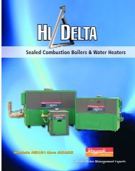
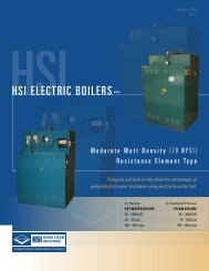
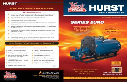
STANDARD FEATURES<strong>Boiler</strong> is of the three-pass, scotch type, built and stamped in accordance with the requirements ofthe ASME Code, and listed by the National Board of <strong>Boiler</strong>s and Pressure Vessel Inspectors.Large combustion chamber with low heat release for complete combustion.Smoke box is rear-mounted with slip-on stack connector.Access to fireside is accomplished with hinged and davited front and rear doors. Flame observationports are located on front and rear.Openings for vessel cleanout and inspection of waterside are provided with 3” x 4” hand holes, and12” x 16” manway access.Insulated with 2” high density mineral wool, lagged with 22 gage grip jacketing, baked on finish toresist chipping and fading.Firetubes are rolled and beaded on power boilers, expanded and flared on low pressure boilers3-PASS FIRETUBE DESIGNWetback Construction100 - <strong>2000</strong> <strong>BHP</strong>STEAMPressures to 15-300 PSI.HOT WATERSection I and Section IVSupports include lifting lugs securely welded to the top of shell; structural steel support legs onskids support the boiler so that special foundations are not required.Stress Relieving “Wetback” Construction for Extra-Long LifeStandard Steam TrimOperating & high limit pressure controlModulating pressure control (when appl.)Water column with gauge glass, combinationlow water cut-off & pump controlProbe Aux, L.W.C.O.Steam pressure gauge, syphon & test cockStandard Water TrimOperating & high limit temperature controlModulating temperature control (when appl.)Probe type low water cut-off controlCombination pressure & temperature gaugeHot water return baffle for shock resistanceWater column drain valveSafety relief valve(s) per ASME CodeSafety relief valve(s) per ASME CodeHBC-0950301/2011Low ProfileCompact DesignWet Back Design Eliminates RefractoryRear Door & Baffles BetweenFlue Gas PassesSHIPS INFREIGHT CONTAINERH U R S T P E R F O R M A N C E S E R I E S B O I L E R S
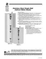
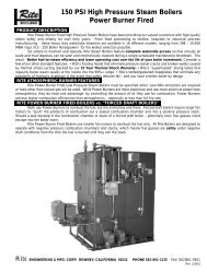
ISERIES EURORSBCNOTE: THE 400 HP SIZEHAS A REMOVABLE STACKSECT'N.FOR SHIPPINGCONSULT FACTORYHOT WATER BOILERWCUT AWAY VIEWKJTUQV12" X 16" MANWAYFAEGDN HPLFRONT VIEWMOSIDE VIEWInspected andregistered with theNational Board of<strong>Boiler</strong> & PressureVessel Inspectors.Designed,constructed andstamped inaccordance withthe requirementsof the ASME<strong>Boiler</strong> Codes.BOILER SPECIFICATIONSBOILER HORSEPOWER 100 125 150 200 250 300 350 400STEAM OUTPUT FROM &@ 212° LBS/HR 3450 4313 5175 6900 8625 10350 12075 13800GROSS OUTPUT @33,475 BTU/<strong>BHP</strong> MBH 3348 4184 5021 6695 8369 10043 11716 13390FIRING RATE GAS 1,000 BTU CFH 4200 5250 6300 8400 10500 12600 14700 16800FIRING RATE LP GAS 91,500 BTU GPH 46 57 69 92 115 138 160 184FIRING RATE OIL #2 140,000 BTU GPH 29.9 37.4 45 60 75 90 105 120FIRING RATE OIL #5 & #6 150,000 BTU GPH 28 35 42 56 70 84 98 112A *NOTE: 1 STEAM OUTLET SIZE 150 PSI IN 4 4 4 4 6 6 6 6 AA *NOTE: 2 STEAM OUTLET SIZE 15 PSI IN 8 8 8 8 10 10 10 10 AB *NOTE: 2 WATER SUPPLY SIZE 30 PSI IN 8 8 8 8 10 10 10 10 BC *NOTE: 2 WATER RETURN SIZE 30 PSI IN 6 6 6 6 8 8 8 8 CD FEEDWATER CONNECTION IN 1 1/4 1 1/4 1 1/4 1 1/2 1 1/2 2 2 2 DE BLOWDOWN CONNECTION (BTM) HIGH PRESS. IN 1 1/4 1 1/4 1 1/4 1 1/4 1 1/4 1 1/2 1 1/2 1 1/2 EE BLOWDOWN CONNECTION (BTM) LOW PRESS. & HW IN 1 1/2 1 1/2 2 2 2 2 2 2 EF STACK OUTLET SIZE O.D. IN 14 14 16 16 18 20 20 24 FG FURNACE O.D. IN 30 30 35 1/4 35 1/4 38 38 38 44 GH SHELL I.D. IN 54 54 66 66 72 75 1/2 75 1/2 78 HI NOTE: 3 SUPPLY HEIGHT 150 PSI IN 74 5/8 74 5/8 87 3/4 87 3/4 93 3/4 97 1/2 97 1/2 93 5/8 IJ WIDTH WITHOUT TRIM IN 60 60 73 73 78 83 83 85 JK WIDTH WITH TRIM IN 67 67 80 80 87 89 89 91 KL SKID WIDTH IN 44 44 51 51 57 60 60 62 LM END OF SKID FROM FRT. PLATE IN 19 11/16 21 11/16 22 11/16 22 11/16 28 5/8 31 5/8 31 5/8 36 MN SHELL TO FLOOR IN 14 14 15 15 15 15 15 14 NO SKID LENGTH IN 120 134 159 165 180 200 206 236 OP STACK HEIGHT IN 74 5/8 74 5/8 87 3/4 87 3/4 93 3/4 97 1/2 97 1/2 104 PQ STEAM OUTLET LOCATION 15 & 150 PSI IN 55 13/16 55 13/16 63 13/16 63 13/16 67 7/8 82 7/8 82 7/8 103 7/8 QR SUPPLY LOCATION IN 35 13/16 35 13/16 39 13/16 39 13/16 45 7/8 50 7/8 50 7/8 55 7/8 RS RETURN LOCATION IN 56 68 80 84 86 96 99 114 ST TUBE REMOVAL FRONT IN 111 123 144 150 161 176 182 209 TU BURNER PROJECTION STANDARD BURNER IN 32 35 35 35 48 52 52 52 UV STACK OUTLET IN 119 13/16 131 13/16 153 13/16 159 13/16 171 7/8 187 7/8 195 7/8 221 7/8 VW APPROX. OVERALL LENGTH IN 162 177 200 206 232 253 263 289 WOVERALL SHIPPING HEIGHT 30 & 150 PSI IN 76 76 89 89 95 99 99 96SHIPPING WEIGHT - HIGH PRESS. 150 PSI LBS 8,300 9,000 13,500 14,650 17,250 20,500 21,000 26,000WATER CAPACITY - STEAM NWL GALS 516 579 1025 967 1406 1538 1555 1748WATER CAPACITY - WATER FLOODED GALS 573 643 1222 1218 1648 1949 2022 2166BOILER HORSEPOWER 100 125 150 200 250 300 350 400500 600 700 750 800 900 1000 1200 1500 1800 <strong>2000</strong>17250 20700 24150 25875 27600 31050 34500 41400 51750 62100 6900016738 20085 23432 25106 26780 30128 33475 40170 50213 60255 6695021000 25200 29400 31500 33600 37800 4<strong>2000</strong> 50400 63000 75600 84000230 275 320 344 368 413 460 550 688 826 918150 180 210 225 240 270 300 360 450 540 600140 168 196 210 224 252 280 336 420 504 560A 6 8 8 8 8 8 8 10 10 *12 *12 AA 10 12 12 12 12 14 14 14 14 *16 *16 AB 10 12 12 12 12 12 12 14 14 *16 *16 BC 8 8 10 10 10 12 12 14 14 *16 *16 CD 2 2 1/2 2 1/2 2 1/2 2 1/2 2 1/2 2 1/2 2 1/2 2 1/2 2 1/2 2 1/2 DE 1 1/2 1 1/2 2 2 2 2 2 2 2 2 2 EE 2 2 2 2 2 2 2 2 2 1/2 2 1/2 2 1/2 EF 24 28 34 34 34 34 34 38 42 *48 *48 FG 50 54 56 56 60 60 60 60 62 66 66 GH 96 102 108 108 112 112 112 126 136 142 142 HI 121 127 133 133 137 1/4 137 1/4 137 1/4 152 1/4 162 1/2 162 162 IJ 102 3/4 108 115 115 119 119 119 133 1/2 144 1/2 149 149 JK 108 1/4 113 1/4 124 124 136 136 136 139 1/2 150 3/4 161 161 KL 76 78 86 86 92 92 92 108 114 124 124 LM 31 5/8 52 5/8 46 5/8 46 5/8 36 5/8 52 1/2 51 1/2 55 5/8 59 5/8 70 76 MN 18 18 18 18 18 18 18 18 18 16 16 NO 212 240 228 228 228 264 288 294 320 336 354 OP 122 128 134 134 138 1/4 138 1/4 138 1/4 152 1/4 162 1/2 162 162 PQ 96 7/8 96 3/8 89 7/8 90 1/2 101 3/8 122 116 122 3/8 135 7/8 134 140 QR 60 3/8 66 3/8 60 7/8 60 7/8 63 68 75 75 74 74 74 RS 162 3/8 168 3/8 162 7/8 162 7/8 165 188 206 206 218 218 230 ST 195 202 196 196 209 231 253 281 281 281 293 TU 65 66 66 70 70 75 75 84 84 96 96 UV 208 7/8 217 7/8 214 3/8 214 3/8 225 7/8 249 1/2 271 1/2 273 1/2 302 7/8 307 319 VW 279 290 299 3/8 303 3/8 312 343 1/2 365 1/2 379 405 429 441 W122 128 134 138 1/4 138 1/4 138 1/4 138 1/4 152 1/4 162 1/2 164 16435,000 38,000 43,000 44,200 49,500 53,750 57,500 72,000 89,000 *89,000 *92,0002390 2688 3405 3348 3590 4015 4443 5855 7176 5855 71653453 3983 4290 4233 4823 5152 5697 7980 10,386 7980 10,532500 600 700 750 800 900 1000 1200 1500 1800 <strong>2000</strong>BOILER DESIGN: Three-Pass“Scotch Marine” Firetube design withstress relieving “Wetback” construction.Pressure designs for steam are15-300 psi. 100-600 hp. 250 psi.max. for 700-1500 hp. and 200 psi.max. for 1800-<strong>2000</strong> hp.Hot Water pressures models arefrom 30-160 psi. High pressure, hightemperature Section I hot waterboilers available.Factory assembled with trim,tested, ASME code, UL, and CSD-1standards.STEAM MODEL TRIM: Safety reliefvalve, operating pressure control,high limit pressure control withmanual reset, steam pressure gaugewith syphon, combination pumpcontrol and low water cut-off withgauge glass assembly and drainvalve, auxiliary low water cut-off withmanual reset.HOT WATER MODEL TRIM: Safetyrelief valve, operating temperaturecontrol, high limit temperature controlwith manual reset, combination pressure& temperature gauge, low watercut-off control with manual reset.BURNER: Matched UL listed “forceddraft” power burners with factory prepiped,wired and tested fuel configurationsfor natural gas, propane (LP)gas, No. 2 (diesel) oil, or combinationof both gas/oil.DIMENSIONS SUBJECT TO CHANGE WITHOUT NOTICE.(NOTE:1) 3”& ABOVE ARE 300# ANSI FLANGE.(NOTE:2) 4” & ABOVE ARE 150# ANSI FLANGE.FOR SECT.-I HIGH –PRESS.STEAM THIS CHART APPLICABLE FOR 50 PSI UP TO 300 PSI.STEAM,AND LOW AND HIGH PRESS.HOT WATER ONLY.FOR STEAM PRESSURES BELOW 50 PSI. AND FOR SECTION-IV LOW PRESS.STEAM BELOW 15PSI. CONSULT FACTORY FOR BOILER DIMENSIONS AND OR CERTIFIED DWGS.* NOTE: 1800 & <strong>2000</strong> HP WEIGHTS DO NOT INCLUDE BURNER OR REFRACTORY HEAD RING.* NOTE: STUDDED OUTLET FLG’S ON 400 HP, 1800-<strong>2000</strong> HP.