VGA to DVI Conversion Box Introduction ... - Avlinksystem.com
VGA to DVI Conversion Box Introduction ... - Avlinksystem.com
VGA to DVI Conversion Box Introduction ... - Avlinksystem.com

You also want an ePaper? Increase the reach of your titles
YUMPU automatically turns print PDFs into web optimized ePapers that Google loves.
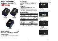
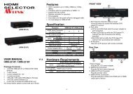
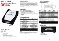
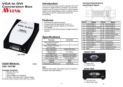
<strong>VGA</strong> <strong>to</strong> <strong>DVI</strong><strong>Conversion</strong> <strong>Box</strong><strong>Introduction</strong>The VD-101W Converter connect <strong>com</strong>puter with HD-15connec<strong>to</strong>r <strong>to</strong> digital moni<strong>to</strong>r or projec<strong>to</strong>r. The converterchanges your PC analog <strong>VGA</strong> signal <strong>to</strong> digital graphicsignal, so that digital display device or projec<strong>to</strong>r can beconnected <strong>to</strong> your PC analog output easily andconveniently.Technical SpecificationsInput/Output Signal(VD-101W)USER MANUAL V1.0VD-101WPackage Contents-• 1 AVLINK VD-101W• 1 user manual• 1 power adapter DC 9V/600mA• 1 AVLINK 1.2M cable (HD-15 Male <strong>to</strong> Male)Any thing missed, please contact with your vendor.Features• Use PanelLink digital technology• Compliant with the specification of <strong>DVI</strong> 1.0• Support high-resolution display up <strong>to</strong> WUXGA(25-165MHz)• Connect PC with <strong>VGA</strong> connec<strong>to</strong>r <strong>to</strong> digital moni<strong>to</strong>r orprojec<strong>to</strong>rSpecificationsFunctionVideo Input Connec<strong>to</strong>r(<strong>VGA</strong> Female)Video Output Connec<strong>to</strong>r(<strong>DVI</strong> Female)Max. ResolutionCable Distance(Single end)Input Signal TypeOutput Signal TypePower Adapter (Min.)HousingWeightDimensions (LxWxH) mmVD-101W111920x1200 60Hz12 m (Max.)Standard <strong>VGA</strong> SignalStandard <strong>DVI</strong> SignalDC 9V 600mAMetal305g128x75x29Note:Different cable qualify might effect upon the maximumresolution and cable distance.-1-Pin # Signal Pin # Signal1 T.M.D.S Data 2- 16 Hot Plug Detect2 T.M.D.S Data 2+ 17 T.M.D.S Data 0-3 T.M.D.S Data 2/4 Shield 18 T.M.D.S Data 0+4 T.M.D.S Data 4- 19 T.M.D.S Data 0/5 Shield5 T.M.D.S Data 4+ 20 T.M.D.S Data 5-6 DDC Clock 21 T.M.D.S Data 5+7 DDC Data 22 T.M.D.S Clock Shield8 Analog Vert. Sync 23 T.M.D.S Clock+9 T.M.D.S Data 1- 24 T.M.D.S Clock-10 T.M.D.S Data 1+11 T.M.D.S Data 1/3 Shield C1 Analog Red12 T.M.D.S Data 3- C2 Analog Green13 T.M.D.S Data 3+ C3 Analog Blue14 +5V Power C4 Analog Horz Sync15 GND C5 Analog GroundFRONT VIEW1. Power LED2. “<strong>VGA</strong> In” PortREAR VIEW1. “<strong>DVI</strong> Out” Port2. Input Power Jack-2-
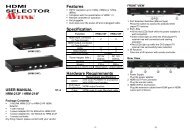
BOTTOM VIEW1. Sharpness adjust (1~4)2. Horizontal adjust (5~9)3. Vertical adjust (10~12)Installation1. Turn off the PC and moni<strong>to</strong>r.2. Connect the <strong>VGA</strong> male extension cable between the PCand the “<strong>VGA</strong> In” port of VD-101W.3. Connect the <strong>DVI</strong> male extension cable between themoni<strong>to</strong>r and the “<strong>DVI</strong> Out” port of VD-101W.4. Connect the power cord and turn on the VD-101W.5. Turn on the PC and digital moni<strong>to</strong>r or projec<strong>to</strong>r.Support <strong>VGA</strong> modeAnalog Resolution Frequency(Hz)<strong>VGA</strong> 640x480 60 / 72 / 75 / 85<strong>VGA</strong> 720x400 70 / 85S<strong>VGA</strong> 800x600 56 / 60 / 72 / 75 / 85W<strong>VGA</strong> 848x480 60XGA 1024x768 60 / 70 / 75 / 85SXGA 1152x864 75SXGA 1280x768 60RB / 75 / 85WXGA 1280x800 60SXGA 1280x960 60 / 85SXGA 1280x1024 60 / 75 / 85WXGA 1360x768 60SXGA+ 1400x1050 60RB / 75WXGA+ 1440x900 60SXGA+ 1440x1050 60UXGA 1600x1200 60WSXGA+ 1680x1050 60WUXGA 1920x1080 60WUXGA 1920x1200 60RB-3-DIP Switch SettingsHorizontal AdjustSW5 SW6 SW7 SW8 SW9 RESULTOFF OFF OFF OFF OFF Left+16OFF OFF OFF OFF ON Left+15OFF OFF OFF ON OFF Left+14OFF OFF OFF ON ON Left+13OFF OFF ON OFF OFF Left+12OFF OFF ON OFF ON Left+11OFF OFF ON ON OFF Left+10OFF OFF ON ON ON Left+9OFF ON OFF OFF OFF Left+8OFF ON OFF OFF ON Left+7OFF ON OFF ON OFF Left+6OFF ON OFF ON ON Left+5OFF ON ON OFF OFF Left+4OFF ON ON OFF ON Left+3OFF ON ON ON OFF Left+2OFF ON ON ON ON Left+1ON OFF OFF OFF OFF 0ON OFF OFF OFF ON Right+1ON OFF OFF ON OFF Right+2ON OFF OFF ON ON Right+3ON OFF ON OFF OFF Right+4ON OFF ON OFF ON Right+5ON OFF ON ON OFF Right+6ON OFF ON ON ON Right+7ON ON OFF OFF OFF Right+8ON ON OFF OFF ON Right+9ON ON OFF ON OFF Right+10ON ON OFF ON ON Right+11ON ON ON OFF OFF Right+12ON ON ON OFF ON Right+13ON ON ON ON OFF Right+14ON ON ON ON ON Right+15Adjust switch “Left + n” when screen position is right slant.Adjust switch “Right + n” when screen position is left slant.-4-Vertical AdjustSW10 SW11 SW12 RESULTOFF OFF OFF Down+4OFF OFF ON Down+3OFF ON OFF Down+2OFF ON ON Down+1ON OFF OFF 0ON OFF ON Up+1ON ON OFF Up+2ON ON ON Up+3Adjust switch “Up + n” when screen position is lower.Adjust switch “Down + n” when screen position is upper.Sharpness AdjustSW1 SW2 SW3 SW4OFF OFF OFF OFFOFF OFF OFF ONOFF OFF ON OFFOFF OFF ON ONOFF ON OFF OFFOFF ON OFF ONOFF ON ON OFFOFF ON ON ONON OFF OFF OFFON OFF OFF ONON OFF ON OFFON OFF ON ONON ON OFF OFFON ON OFF ONON ON ON OFFON ON ON ONAdjust switch “Sharpness” To correct flickering text or line.© C&C TECHNIC TAIWAN CO., LTD. All rights reserved.Trademarks:All the <strong>com</strong>panies, brand names, and product namesreferred <strong>to</strong> this manual are the trademarks orregistered trademarks belonging <strong>to</strong> their respective<strong>com</strong>panies.-5-