Robot tool changers - Romheld
Robot tool changers - Romheld
Robot tool changers - Romheld
- No tags were found...

You also want an ePaper? Increase the reach of your titles
YUMPU automatically turns print PDFs into web optimized ePapers that Google loves.
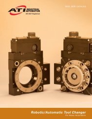
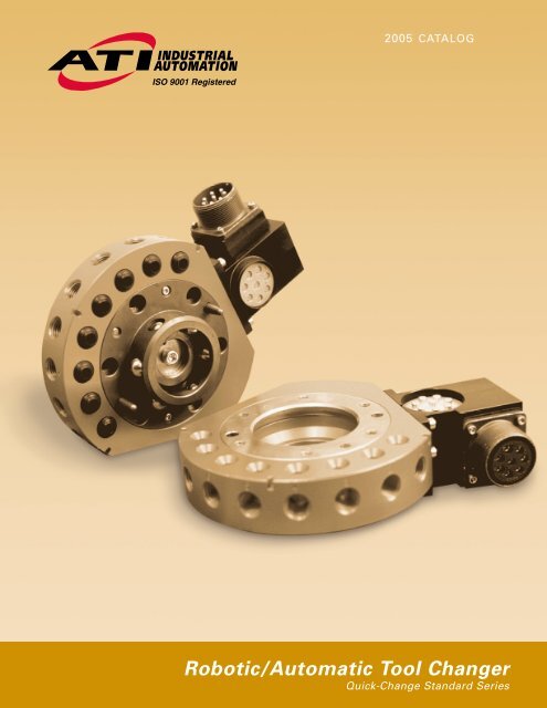
2005 CATALOG<strong>Robot</strong>ic/Automatic Tool ChangerQuick-Change Standard Series
TOOL CHANGERSProduct DescriptionThe Quick-Change provides flexibility to robotapplications by allowing the robot to change end-effectors(e.g. grippers, vacuum cup <strong>tool</strong>ing, pneumatic and electricmotors, weld guns, etc.) automatically. The Quick-Changeconsists of a Master plate and a Tool plate.The Master plate, installed on the robot arm, locksto the Tool plate with a pneumatically-driven lockingmechanism. This locking mechanism uses a patented,double-tapered piston with ball locking technology anda patented fail-safe mechanism. The Master allows forthe passage of pneumatic and electrical connections tothe Tool plate.The Tool plate is attached to each end-effector. TheTool plate interfaces with the Master plate’s pneumaticand electrical connections and passes them on to theend-effector.General Tool Changer AdvantagesLines changed in seconds instead of hours.Increase operator safety by changing <strong>tool</strong>s automatically.Change <strong>tool</strong>s in seconds for maintenance and repair.Increase flexibility of your robots by adding the abilityto use more than one end-effector in an application.Heavy and large multi-<strong>tool</strong> end-effectors replacedwith individual <strong>tool</strong>s that are automatically exchanged.ATI Tool Changer AdvantagesSuperior Fail-safe Locking: The locking mechanismhas a built-in, patented fail-safe feature that keeps theTool plate secured to the Master plate in the event ofpneumatic pressure loss. This fail-safe featureeliminates the need for a spring.High Rigidity: The Quick-Change has a high momentcapacity due to the locking piston’s large diameter andsecond taper. The Quick-Change does not rock duringhigh-inertia moves, preventing locking failure orrepeatability problems.Unmatched Repeatability: The piston acts as a largedowel pin, aligning the master and <strong>tool</strong> with remarkablerepeatability. Repeatability specifications are based onmillion-cycle testing.No-Touch Locking TM Technology: The Quick-Changecan lock successfully with a gap between the Masterand Tool plates.3 Year Warranty: Our warranty is based on years ofobservation and analysis by our customers in the fieldand extensive laboratory testing.Simple Interface: Plate design allows for easy robotmounting.Quick-Change Family (left to right from back row; Master plate is standing, Tool plate islying flat directly in front of each Master plate); QC-110; QC-60; QC-20; QC-41; QC-150;Front row: QC-40; QC-5; QC-21.2 VISIT WWW.ATI-IA.COM FOR CURRENT PRODUCT SPECIFICATIONS, 2-D DRAWINGS, AND 3-D CAD MODELS
Quick-Change Locking Mechanism *Our patented locking mechanism and uniquefail-safe feature have been in industrial use formore than ten years without failure.“...we purchased a trial set of <strong>tool</strong> <strong>changers</strong> for one cell. Itproved to work really well... We now have a working systemthat is a benchmark, not only for our corporation, but ourcompetitors as well.”John Jackson,Automation Area andTooling Construction SupervisorFigure 1: Tool changer in unlockedpositionInterface plateMaster plateElectrical module (Master side)Male couplerTool plateElectrical module (Tool side)Hardened steel ball is onthe first taper of the cam.Figure 2a: Close-up of locking ballposition with <strong>tool</strong> changer readyto lockFigure 2b: Section view of <strong>tool</strong> changerready to lock (interface plate not shown)PistonCamNo-Touch Locking Lock ringHardened steel ball is on thesecond taper of the cam.Fail-safe cylindrical surfaceFirst taperFigure 3a: Close-up of locking ballin locked positionLock air pressure pushes thepiston down, driving the ballsout and under the lock ring,pulling up the <strong>tool</strong> plate.Figure 3b: Section view of <strong>tool</strong> changerlockedHardened steel ball is onfail-safe cylindrical surface.The cam will not move unlessunlock air pressure is applied,preventing the <strong>tool</strong> plate fromfalling off.Figure 4a: Close-up of locking ballposition while in fail-safe modeIn the event lock pressureis removed, the balls aretrapped by the cam. Sealfriction prevents the pistonfrom moving due to gravity orvibration. Unlock pressure isrequired to move the cam upto the unlocked position.Figure 4b: Section view of <strong>tool</strong> changerin fail-safe mode*Video available on website.VISIT WWW.ATI-IA.COM FOR CURRENT PRODUCT SPECIFICATIONS, 2-D DRAWINGS, AND 3-D CAD MODELS 3
MODEL SELECTIONHow to Select a <strong>Robot</strong>ic Tool Changer1. Sizinga. Fast method: If the expected moment exerted on the<strong>tool</strong> changer is low or moderate, select a Quick-Changemodel with a payload rating similar to that of your robot.If the expected moment is high, or if you prefer to usea QC model better suited to the application, see section(b) below.b. More exact method: Moment capacity is a criticalfactor in selecting the proper Quick-Change model. Usethe following to approximate the worst-case moment.a) Find the approximate center-of-gravity (CG) of theheaviest end-effector to be used.b) Calculate the distance (D) from the CG to thebottom of the Tool plate (example below).c) Calculate the weight (W) of the heaviest endeffector.d) Multiply W by D to get an approximate staticmoment (M) (or a moment based on one G ofacceleration).e) Select a Quick-Change with a moment capacityequal to or greater than M.<strong>Robot</strong>s may produce moments two-to-three times higherthan M due to their potentially high acceleration. TheQuick-Change models are designed to handle dynamicmoments three times higher than their static momentratings.2. Pneumatic and Electrical: Determine the number andsize of pneumatic ports and electrical contacts needed.Larger Quick-Change models have a greater number ofpneumatic ports and electrical contacts.3. Temperature and Chemicals: The Quick-Changeuses nitrile bushings to pass air to the Tool plate, andBuna-N O-rings to seal the pneumatic locking mechanism.Not only is this rubber material resistant to mostchemicals, it is able to withstand temperatures rangingfrom -20°F to 150°F. Please contact your sales personfor information regarding temperatures or chemicals forparticular environments.4. Precision Applications: Be sure to refer to thespecifications when dealing with applications that requirehigh repeatability.Remember: A <strong>tool</strong> changer affects robot momentcapacity, payload, size and repeatability. For comparablepayloads the Quick-Change is designed to exceed therobot’s specifications.4 VISIT WWW.ATI-IA.COM FOR CURRENT PRODUCT SPECIFICATIONS, 2-D DRAWINGS, AND 3-D CAD MODELS
Table of ContentsQuick-View Specification Table . . . . . . . . . . . . . . . . .5QC-5 . . . . . . . . . . . . . . . . . . . . . . . . . . . . . . . . . . . .6QC-11 . . . . . . . . . . . . . . . . . . . . . . . . . . . . . . . . . . .8QC-20 . . . . . . . . . . . . . . . . . . . . . . . . . . . . . . . . . .10QC-21 . . . . . . . . . . . . . . . . . . . . . . . . . . . . . . . . . .12Tool Stands for QC-5 to QC-21 . . . . . . . . . . . . . . . .14QC-40 . . . . . . . . . . . . . . . . . . . . . . . . . . . . . . . . . .16QC-41 . . . . . . . . . . . . . . . . . . . . . . . . . . . . . . . . . .18QC-60 . . . . . . . . . . . . . . . . . . . . . . . . . . . . . . . . . .20QC-71 . . . . . . . . . . . . . . . . . . . . . . . . . . . . . . . . . .22QC-110 . . . . . . . . . . . . . . . . . . . . . . . . . . . . . . . . .24QC-150 . . . . . . . . . . . . . . . . . . . . . . . . . . . . . . . . .26QC-300 . . . . . . . . . . . . . . . . . . . . . . . . . . . . . . . . .28Tool Stands for QC-40 to QC-150 . . . . . . . . . . . . . .30Sensor Interface Plate System . . . . . . . . . . . . . . . .32Electrical & Pneumatic Modules & Options . . . . . .33“It is highly recommended that ATI’s <strong>tool</strong> changer beconsidered when looking at any kind of automatic <strong>tool</strong>disconnect or application using this type of design.”Joe MitoryASME Project ManagerQuick-View Specification TableDescription QC-5 QC-11 QC-20 QC-21 QC-40 QC-41Suggested Payload Limit 18 lb 35 lb 55 lb 55 lb 110 lb 110 lb(8 kg) (16 kg) (25 kg) (25 kg) (50 kg) (50 kg)Locking Force @ 80 psi (5.5 bar) 155 lb 240 lb 520 lb 520 lb 1020 lb 1020 lb(690 N) (1068 N) (2314 N) (2314 N) (4540 N) (4540 N)Static Moment Capacity (X & Y)** 110 lb-in 220 lb-in 500 lb-in 500 lb-in 1390 lb-in 1390 lb-in(12.5 N-m) (25 N-m) (56.5 N-m) (56.5 N-m) (157 N-m) (157 N-m)Static Moment Capacity (Z) 150 lb-in 300 lb-in 690 lb-in 690 lb-in 1910 lb-in 1910 lb-in(17 N-m) (34 N-m) (78 N-m) (78 N-m) (216 N-m) (216 N-m)Pneumatic pass-through (6) M5 (6) M5 (12) M5* (8) (8)* (6) 3/8 NPT(Quantity) size or #10-32 or #10-32 or #10-32 1/8 NPT 1/8 NPT (4) 1/8 NPTPneumatic Lock & Unlock port size M5 M5 M5 M5 1/8 NPT 1/8 NPTor #10-32 or #10-32 or #10-32 or #10-32Description QC-60 QC-71 QC-110 QC-150 QC-300Suggested Payload Limit 165 lb 175 lb 330 lb 440 lb 1003 lb(75 kg) (79 kg) (150 kg) (200 kg) (455 kg)Locking Force @ 80 psi (5.5 bar) 1660 lb 1815 lb 2730 lb 3620 lb 7940 lb(7387 N) (8075 N) (12149 N) (16109 N) (35333 N)Static Moment Capacity (X & Y)** 1740 lb-in 3500 lb-in 6940 lb-in 12000 lb-in 29100 lb-in(197 N-m) (395 N-m) (784 N-m) (1356 N-m) (3870 N-m)Static Moment Capacity (Z) 2600 lb-in 3500 lb-in 6940 lb-in 10000 lb-in 25000 lb-in(294 N-m) (395 N-m) (784 N-m) (1130 N-m) (2825 N-m)Pneumatic pass-through (8)* (8)* (8)* (10)* (10)*(Quantity) size 1/8 NPT 1/4 NPT 3/8 NPT 3/8 NPT 3/8 BSPPPneumatic Lock & Unlock port size 1/8 NPT 1/8 NPT 1/8 NPT 1/8 NPT 1/4 BSPP*Additional pneumatic pass-through ports are available for these models. **All models can handle a dynamic moment 3 times higher than the static momentcapacity. Moment tests show failure point at 10-12 times X & Y static moment specifications.†Higher payloads possible with low moment.VISIT WWW.ATI-IA.COM FOR CURRENT PRODUCT SPECIFICATIONS, 2-D DRAWINGS, AND 3-D CAD MODELS 5
QC-5Product AdvantagesMaster Forces Separation of Tool to prevent stickingwhile unlocking—a common problem when workingwith light payloads.Extremely High RepeatabilityNo-Touch Locking TM technology allows up to 3.0 mmplate separation when locking.Patented Fail-safe Locking MechanismLong-life Bushings for Pneumatic Pass-throughQC-5 Master and Tool plate with E2A electrical moduleSpecifications Values CommentsSuggested Payload Limit 18 lb (8 kg) Higher payloads possible with low moment.Locking Force @ 80 psi (5.5 bar) 155 lb (690 N) Fail-safe takes over when load exceeds locking force.Static Moment Capacity – X & YStatic Moment Capacity – Z110 lb-in(12.5 Nm)150 lb-in(17 Nm)Dynamic moment capacity 3x higher than static momentcapacity. Tests show failure point at 12x X & Y staticmoment specifications.Positional Repeatability – X,Y, & Z 0.0004 in Repeatability tested at rated load at one million cycles.(0.010 mm)Weight – when coupled 0.81 lb Master plate 0.60 lb (0.27 kg); Tool plate 0.21 lb (0.10 kg)(with no accessory modules)(0.37 kg)Minimum/Maximum distance between 0.06 in/0.12 in No-Touch Locking technology allows Master & ToolMaster & Tool plate before locking 1.5 mm/3.0 mm plates to lock with plate separation.Pneumatic pass-through Ports (qty) size (6) M5 or #10-32 Max pressure of 100 psi (7 bar)Note:Modules and options available.See pg. 33-35.Tool Stand and components areavailable for this model. See pg. 14.QC-5 with E3A electrical moduleQC-5 with B15 electrical module6 VISIT WWW.ATI-IA.COM FOR CURRENT PRODUCT SPECIFICATIONS, 2-D DRAWINGS, AND 3-D CAD MODELS
QC-11Product AdvantagesLightweight and Small Size with a high-strengthlocking mechanism.No-Touch Locking TM technology allows up to 3.0 mmplate separation when locking.Patented Fail-safe Locking Mechanism• Locking Mechanism design results in low forceacting on the piston.• Large piston diameter and outward ball travelincrease moment capacity.• All locking parts made of R c 58 stainless steel.Long-life Bushings for Pneumatic Pass-throughQC-11 with A15 electrical moduleSpecifications Values CommentsSuggested Payload Limit 35 lb (16 kg) Higher payloads possible with low moment.Locking Force @ 80 psi (5.5 bar) 240 lb (1068 N) Fail-safe takes over when load exceeds locking force.Static Moment Capacity – X & YStatic Moment Capacity – Z220 lb-in(25 Nm)300 lb-in(34 Nm)Dynamic moment capacity 3x higher than static momentcapacity. Tests show failure point at 12x X & Y staticmoment specifications.Positional Repeatability – X,Y, & Z 0.0004 in Repeatability tested at rated load at one million cycles.(0.010 mm)Weight – when coupled 0.46 lb Master plate 0.28 lb (0.13 kg); Tool plate 0.18 lb (0.08 kg)(with no accessory modules)(0.21 kg)Maximum distance between 0.12 in No-Touch Locking technology allows Master & ToolMaster & Tool plate before locking (3.0 mm) plates to lock with plate separation.Pneumatic pass-through Ports (qty) size (6) M5 or #10-32 Max pressure of 100 psi (7 bar)QC-11 w/E10 electrical moduleQC-11 w/E20 electrical moduleNote:Modules and options available.See pg. 33-35.For payloads less than 2 lbs. (.9 kg),use the QC-5 <strong>tool</strong> changer.Tool Stand and components areavailable for this model. See pg. 14.8 VISIT WWW.ATI-IA.COM FOR CURRENT PRODUCT SPECIFICATIONS, 2-D DRAWINGS, AND 3-D CAD MODELS
HOW TO ORDER9120-011 - -000 QC-11Example:Option (000 = no option)M: MasterT: Tool9120-011M-000-000(QC-11 Master plate, no options)9120-011T-A15-000(QC-11 Tool plate w/ A15 electrical module)“ATI’s QC-11 coupler will allow our engineers to keepour end<strong>tool</strong> design small and maneuverable withoutsacrificing quality. ATI engineers have been great towork with during every step of the selection process.”Denise CarliniPrime AutomationATI INDUSTRIAL AUTOMATION www.ati-ia.com QC-11 9230-20-1963-01VISIT WWW.ATI-IA.COM FOR CURRENT PRODUCT SPECIFICATIONS, 2-D DRAWINGS, AND 3-D CAD MODELS 9
QC-20Product AdvantagesLarge Number of Pass-through Air PortsNo-Touch Locking TM technology allows up to 3.0 mmplate separation when locking.Patented Fail-safe Locking Mechanism• Locking Mechanism design results in low forceacting on the piston.• Large piston diameter and outward ball travelincrease moment capacity.• All locking parts made of R c 58 stainless steel.Long-life Bushings for Pneumatic Pass-throughQC-20 Master and Tool plate with K19 electrical moduleSpecifications Values CommentsSuggested Payload Limit 55 lb (25 kg) Higher payloads possible with low moment.Locking Force @ 80 psi (5.5 bar) 520 lb (2314 N) Fail-safe takes over when load exceeds locking force.Static Moment Capacity – X & YStatic Moment Capacity – Z500 lb-in(56.5 Nm)690 lb-in(78 Nm)Dynamic moment capacity 3x higher than static momentcapacity. Tests show failure point at 12x X & Y staticmoment specifications.Positional Repeatability – X,Y, & Z 0.0006 in Repeatability tested at rated load at one million cycles.(0.015 mm)Weight – when coupled 1.8 lb Master plate 1.1 lb (0.5 kg); Tool plate 0.7 lb (0.3 kg)(with no accessory modules)(0.8 kg)Maximum distance between 0.12 in No-Touch Locking technology allows Master & ToolMaster & Tool plate before locking (3.0 mm) plates to lock with plate separation.Pneumatic pass-through Ports (qty) size (12) M5 or #10-32 Max pressure of 100 psi (7 bar)QC-20 with K26 electrical moduleQC-20 with KM14 electrical moduleNote:Modules and options available.See pg. 33-35.Tool Stand and components areavailable for this model. See pg. 14.Lock/Unlock Sensors with robotinterface plate are available for thismodel. See pg. 32.10 VISIT WWW.ATI-IA.COM FOR CURRENT PRODUCT SPECIFICATIONS, 2-D DRAWINGS, AND 3-D CAD MODELS
HOW TO ORDER9120-020 - -PM5QC-20Option (000 = no option)M: MasterT: ToolExample:9120-020M-000-PM5(QC-20 Master plate, no options)9120-020T-K19-PM5(QC-20 Tool plate w/ K19 electrical module)“What originally drew us to use the ATI <strong>tool</strong> changer was thelow profile and hardened locating features. ATI also providesthe greatest number of air and electrical connections throughthe <strong>tool</strong> changer. We continue to use ATI’s <strong>tool</strong> <strong>changers</strong> becausewe know they work, and we can get the service we need fromATI as a vendor.”Jim WilliamsProject EngineerATI INDUSTRIAL AUTOMATION www.ati-ia.com QC-20 9230-20-1964-01VISIT WWW.ATI-IA.COM FOR CURRENT PRODUCT SPECIFICATIONS, 2-D DRAWINGS, AND 3-D CAD MODELS 11
QC-21Product AdvantagesLarge 1/8 NPT Ports in a small lightweight packageNo-Touch Locking TM technology allows up to 3.0 mmplate separation when locking.Patented Fail-safe Locking Mechanism• Locking Mechanism design results in low forceacting on the piston.• Large piston diameter and outward ball travelincrease moment capacity.• All locking parts made of R c 58 stainless steel.Long-life Bushings for Pneumatic Pass-throughQC-21 Master and Tool plate with K19 electrical moduleSpecifications Values CommentsSuggested Payload Limit 55 lb (25 kg) Higher payloads possible with low moment.Locking Force @ 80 psi (5.5 bar) 520 lb (2314 N) Fail-safe takes over when load exceeds locking force.Static Moment Capacity – X & YStatic Moment Capacity – Z500 lb-in(56.5 Nm)690 lb-in(78 Nm)Dynamic moment capacity 3x higher than static momentcapacity. Tests show failure point at 12x X & Y staticmoment specifications.Positional Repeatability – X,Y, & Z 0.0006 in Repeatability tested at rated load at one million cycles.(0.015 mm)Weight – when coupled 1.8 lb Master plate 1.1 lb (0.5 kg); Tool plate 0.7 lb (0.3 kg)(with no accessory modules)(0.8 kg)Maximum distance between 0.12 in No-Touch Locking technology allows Master & ToolMaster & Tool plate before locking (3.0 mm) plates to lock with plate separation.Pneumatic pass-through Ports (qty) size (8) 1/8 NPT Max pressure of 100 psi (7 bar)QC-21 with K26 electrical moduleQC-21 with KM14 electrical moduleNote:Modules and options available.See pg. 33-35.Tool Stand and components areavailable for this model. See pg. 14.Lock/Unlock Sensors with robotinterface plate are available for thismodel. See pg. 32.12 VISIT WWW.ATI-IA.COM FOR CURRENT PRODUCT SPECIFICATIONS, 2-D DRAWINGS, AND 3-D CAD MODELS
HOW TO ORDER9120-021 - - QC-21Option B (000 = no option)Option A (000 = no option)M: MasterT: ToolExample:9120-021M-000-000(QC-21 Master plate, no options)9120-021T-K19-000(QC-21 Tool plate w/ K19 electrical module)“ATI units have the best locking mechanismin event of air failure.”Matthew Cygler<strong>Robot</strong>ic Automation PTY LTDATI INDUSTRIAL AUTOMATION www.ati-ia.com QC-21 9230-20-1965-01VISIT WWW.ATI-IA.COM FOR CURRENT PRODUCT SPECIFICATIONS, 2-D DRAWINGS, AND 3-D CAD MODELS 13
TOOL STANDS FOR QC-5 TO QC-21TSS Modular Tool Stand SystemThe ATI Modular Tool Stand System,or TSS, is compatible with the smallrange of ATI Tool Changers—modelsQC-5 through QC-21. The Stand isdesigned for maximum flexibility tofit most customers’ applications.The modular system allows you toessentially “build your own” <strong>tool</strong>storage rack based on the numberof <strong>tool</strong>s, positioning, and mountingarrangements desired. The TSS system provides a uniqueoption to either use interface plates or empty air ports onthe <strong>tool</strong> changer as attachment points for your <strong>tool</strong>ing.FeaturesModular System allows for customizationV-Grooves provide repeatable <strong>tool</strong> drop-off locationUse Extruded Rail and Base, or mount the racks onyour own platformDurable Stainless Steel Interface PinsProximity Sensor OptionUse Optional Interface Plate or thread pins intounused ports to save stack heightRack AssemblyThe TSS Rack Assembly includes a rigid “U” shaped plate that interfaceswith the customer’s <strong>tool</strong>ing. The assembly includes mounting hardware,and is designed to mount to the TSS Mounting Block, TSS 3 or 4 ToolAdapter Bar, or TSS Forward Adapter. The Rack can be mounted to anyother surface that has the corresponding mounting features. Each Rackhas V-grooves that interface with stainless steel alignment pins mountedto the <strong>tool</strong>ing. This Groove-Pin combination allows for compliance in thehorizontal plane, and also provides repeatable <strong>tool</strong> positioning.Interface Plate AssemblyThe TSS Interface Plate Assembly simply provides an interface betweenyour <strong>tool</strong> and the Tool Changer. The Interface plates are sized specificallyto correspond with the Tool Changer and TSS Rack. The TSS InterfacePlate assembly also includes 3 stainless steel alignment pins thatinterface with the V-grooves on the TSS Rack. The standard interfaceplates are sold blank to allow customers to machine their own <strong>tool</strong>ingbolt patterns. ATI can provide specific <strong>tool</strong>ing patterns upon request.Base AssemblyThe TSS Base Assembly consists of a square aluminum machined plateand hardware that attaches to the TSS Rail, and TSS Gusset Assembly.The base provides a secure foundation on which to build the Tool StandSystem.Rail-and-Gusset AssembliesThe TSS Rail-and-Gusset assemblies mount to the Base Assembly andinclude alignment and mounting hardware. The standard TSS Rail is analuminum extrusion (Bosch 45x90 series) and is approximately 24 incheslong. Customers can request custom lengths when ordering. The TSSGusset (Bosch type 90x90) provides additional structural support at theTool Stand Base.Mounting BlockThe TSS Mounting Block Assembly mounts to the Rail. It can bepositioned anywhere along the rail to the desired height. Once thedesired height is determined, it is recommended that dowel holes bedrilled into the rail as specified in drawing # 9230-20-1675. These dowelsare needed to ensure accurate positioning over the life of the stand. TheTSS Rack, or Tool Adapter Bars can then mount to the Block. The Blockalso can accommodate a Proximity Sensor Holder.Adapter BarsCurrently there are 3 types of adapter bars. The 3-Tool Adapter Barmounts to the Mounting Block and can hold up to three TSS Racks. The4- and 5- Tool Adapter Bars are similar but can hold 4 or 5 TSS Racks atonce respectively. Each Adapter Bar also allows for the attachment of aProximity Sensor Holder for each Rack. The Forward Adapter Bar is alsoavailable, used when your <strong>tool</strong>ing requires extra clearance from the Rail.14 VISIT WWW.ATI-IA.COM FOR CURRENT PRODUCT SPECIFICATIONS, 2-D DRAWINGS, AND 3-D CAD MODELS
Quick Change TSS Tool Stand InterfacingOption #1: Use Interface PlatesQC Model QC-5 QC-10 QC-11 QC-20 QC-21 QC-21 (Euro)Rack Assembly 9120-TSS-3310 9120-TSS-3310 9120-TSS-3310 9120-TSS-3313 9120-TSS-3313 9120-TSS-3313Interface Plate Assy 9120-TSS-3314 9120-TSS-3314 9120-TSS-3314 9120-TSS-3319 9120-TSS-3319 9120-TSS-3319Alignment Pin 3700-20-3303 3700-20-3303 3700-20-3303 3700-20-3303 3700-20-3303 3700-20-3303Notes See Note 3 See Note 3 See Note 3 See Note 3 See Note 3 See Note 3Prox Sensor Yes Yes Yes Yes Yes YesCustomer Drawing 9230-20-1656 9230-20-1657 9230-20-1658 9230-20-1659 9230-20-1660 9230-20-1662Option #2 Use QC Air PortsQC Model QC-5 QC-10 QC-11 QC-20 QC-21 QC-21 (Euro)Rack Assembly 9120-TSS-3312 9120-TSS-3310 9120-TSS-3310 9120-TSS-3305 9120-TSS-3313 9120-TSS-3313Pin Block none none none none 9120-TSS-3317 9120-TSS-3360Alignment Pin 3700-20-3303 3700-20-3303 3700-20-3303 3700-20-3303 3700-20-3316 3700-20-3320Notes See Note 5 See Note 5Prox Sensor Yes No No Yes Yes YesCustomer Drawing 9230-20-1656 9230-20-1657 9230-20-1658 9230-20-1659 9230-20-1660 9230-20-1662Configurable Tool Stand Module System – Overview Drawing # 9230-20-1675Module Name Post Rail 610mm Post Rail 914mm Post Rail 1220mm 3-Tool Adapter Bar 4-Tool Adapter Bar 5-Tool Adapter BarPart Number 9120-TSS-1020 9120-TSS-3324 9120-TSS-3325 9120-TSS-3308 9120-TSS-3431 9120-TSS-3570Notes See Note 1 See Note 1 See Note 1Customer Drawing 9230-20-1675 9230-20-1912 9230-20-1913 9230-20-1675 9230-20-1775 9230-20-1914Module Name Gusset Forward Adapter Prox Holder Base Mounting Block Alignment Pins:Part Number 9120-TSS-1030 9120-TSS-3361 9120-TSS-3315 9120-TSS-3311 9120-TSS-3306Notes See Notes 2,6 See Note 4Customer Drawing 9230-20-1675 9230-20-1679 9230-20-1675 9230-20-1675 9230-20-16753700-20-33033700-20-33163700-20-3320Notes: 1. May specify other rail lengths—cut charge will apply. 6. Compatible Prox Sensors and Cables: 7. Drawings available for download at2. Sensor Holder will fit any 8mm Diameter Sensor. 8590-9909999-08 - PNP 3 Wire DC www.ati-ia.com.3. 3 Pins come standard with Tool Interface Plates. 8590-9909999-09 - NPN 3 Wire DC4. Alignment Pins are available individually. 8590-9909999-07 - 5 Meter Cable5. Alignment Pins not included in Pin Block. 8590-9909999-12 - 2 Meter CableVISIT WWW.ATI-IA.COM FOR CURRENT PRODUCT SPECIFICATIONS, 2-D DRAWINGS, AND 3-D CAD MODELS 15
QC-40Product AdvantagesTwice the Strength of the QC-20No-Touch Locking TM technology allows up to 5.0 mmplate separation when locking.Patented Fail-safe Locking Mechanism• Locking Mechanism design results in low forceacting on the piston.• Large piston diameter and outward ball travelincrease moment capacity.• All locking parts made of R c 58 stainless steel.Long-life Bushings for Pneumatic Pass-throughQC-40 Master and Tool plate with J16 electrical moduleSpecifications Values CommentsSuggested Payload Limit 110 lb (50 kg) Higher payloads possible with low moment.Locking Force @ 80 psi (5.5 bar) 1020 lb (4540 N) Fail-safe takes over when load exceeds locking force.Static Moment Capacity – X & YStatic Moment Capacity – Z1390 lb-in(157 Nm)1910 lb-in(216 Nm)Dynamic moment capacity 3x higher than static momentcapacity. Tests show failure point at 12x X & Y staticmoment specifications.Positional Repeatability – X,Y, & Z 0.0006 in Repeatability tested at rated load at one million cycles.(0.015 mm)Weight – when coupled 3.8 lb Master plate 2.5 lb (1.1 kg); Tool plate 1.3 lb (0.6 kg)(with no accessory modules)(1.7 kg)Maximum distance between 0.20 in No-Touch Locking technology allows Master & ToolMaster & Tool plate before locking (5.0 mm) plates to lock with plate separation.Pneumatic pass-through Ports (qty) size (8) 1/8 NPT Max pressure of 100 psi (7 bar)QC-40 with S19 electrical moduleQC-40 with R19 electrical module andFN2 fluid moduleNote:Modules and options available.See pg. 33-35.Tool Stand and components areavailable for this model. See pg. 30.Lock/Unlock Sensors with robotinterface plate are available for thismodel. See pg. 32.16 VISIT WWW.ATI-IA.COM FOR CURRENT PRODUCT SPECIFICATIONS, 2-D DRAWINGS, AND 3-D CAD MODELS
HOW TO ORDER9120-040 - - QC-40Option B (000 = no option)Option A (000 = no option)M: MasterT: ToolExample:9120-040M-000-000(QC-40 Master plate, no options)9120-040T-J16-000(QC-40 Tool plate w/ J16 electrical module)9120-040M-R19-FN2(QC-40 Master plate w/ R19 electrical module& FN2 self-sealing fluid module)"Our customers using medium payload robotsselect the QC-40 for flexibility, compactnessand 100% uptime reliability."Steve TatemTIAATI INDUSTRIAL AUTOMATION www.ati-ia.com QC-40 9230-20-1966-01VISIT WWW.ATI-IA.COM FOR CURRENT PRODUCT SPECIFICATIONS, 2-D DRAWINGS, AND 3-D CAD MODELS 17
QC-41Product AdvantagesLarge 3/8 NPT PortsNo-Touch Locking TM technology allows up to 5.0 mmplate separation when locking.Patented Fail-safe Locking Mechanism• Locking Mechanism design results in low forceacting on the piston.• Large piston diameter and outward ball travelincrease moment capacity.• All locking parts made of R c 58 stainless steel.Long-life Bushings for Pneumatic Pass-throughQC-41 Master and Tool plate with R19 electrical moduleSpecifications Values CommentsSuggested Payload Limit 110 lb (50 kg) Higher payloads possible with low moment.Locking Force @ 80 psi (5.5 bar) 1020 lb (4540 N) Fail-safe takes over when load exceeds locking force.Static Moment Capacity – X & YStatic Moment Capacity – Z1390 lb-in(157 Nm)1910 lb-in(216 Nm)Dynamic moment capacity 3x higher than static momentcapacity. Tests show failure point at 12x X & Y staticmoment specifications.Positional Repeatability – X,Y, & Z 0.0006 in Repeatability tested at rated load at one million cycles.(0.015 mm)Weight – when coupled 4.6 lb Master plate 3 lb (1.4 kg); Tool plate 1.6 lb (0.7 kg)(with no accessory modules)(2.1 kg)Maximum distance between 0.20 in No-Touch Locking technology allows Master & ToolMaster & Tool plate before locking (5.0 mm) plates to lock with plate separation.Pneumatic pass-through Ports (qty) size (6) 3/8 NPT Max pressure of 100 psi (7 bar)(4) 1/8 NPTQC-41 with J16 electrical moduleQC-41 with G19 electrical moduleNote:Modules and options available.See pg. 33-35.Tool Stand and components areavailable for this model. See pg. 30.Lock/Unlock Sensors with robotinterface plate are available for thismodel. See pg. 32.18 VISIT WWW.ATI-IA.COM FOR CURRENT PRODUCT SPECIFICATIONS, 2-D DRAWINGS, AND 3-D CAD MODELS
HOW TO ORDER9120-041 - -000 QC-41Example:Option (000 = no option)M: MasterT: Tool9120-041M-000-000(QC-41 Master plate, no options)9120-041T-R19-000(QC-41 Tool plate w/ R19 electrical module)“A well-built durable product that is easily integrated.”Tom WashburnRPTATI INDUSTRIAL AUTOMATION www.ati-ia.com QC-41 9230-20-1967-01VISIT WWW.ATI-IA.COM FOR CURRENT PRODUCT SPECIFICATIONS, 2-D DRAWINGS, AND 3-D CAD MODELS 19
QC-60Product AdvantagesLightweight Design with High StrengthNo-Touch Locking TM technology allows up to 5.0 mmplate separation when locking.Patented Fail-safe Locking Mechanism• Locking Mechanism design results in low forceacting on the piston.• Large piston diameter and outward ball travelincrease moment capacity.• All locking parts made of R c 58 stainless steel.Long-life Bushings for Pneumatic Pass-throughQC-60 Master and Tool plate with K19 electrical moduleSpecifications Values CommentsSuggested Payload Limit 165 lb (75 kg) Higher payloads possible with low moment.Locking Force @ 80 psi (5.5 bar) 1660 lb (7387 N) Fail-safe takes over when load exceeds locking force.Static Moment Capacity – X & YStatic Moment Capacity – Z1740 lb-in(197 Nm)2600 lb-in(294 Nm)Dynamic moment capacity 3x higher than static momentcapacity. Tests show failure point at 12x X & Y staticmoment specifications.Positional Repeatability – X,Y, & Z 0.0006 in Repeatability tested at rated load at one million cycles.(0.015 mm)Weight – when coupled 4.4 lb Master plate 2.9 lb (1.3 kg); Tool plate 1.5 lb (0.7 kg)(with no accessory modules)(2.0 kg)Maximum distance between 0.20 in No-Touch Locking technology allows Master & ToolMaster & Tool plate before locking (5.0 mm) plates to lock with plate separation.Pneumatic pass-through Ports (qty) size (8) 1/8 NPT Max pressure of 100 psi (7 bar)QC-60 with K26 electrical moduleQC-60 with D15 electrical moduleNote:Modules and options available.See pg. 33-35.Tool Stand and components areavailable for this model. See pg. 30.Lock/Unlock Sensors with robotinterface plate are available for thismodel. See pg. 32.20 VISIT WWW.ATI-IA.COM FOR CURRENT PRODUCT SPECIFICATIONS, 2-D DRAWINGS, AND 3-D CAD MODELS
HOW TO ORDER9120-060 - - QC-60Option B (000 = no option)Option A (000 = no option)M: MasterT: ToolExample:9120-060M-000-000(QC-60 Master plate, no options)9120-060T-K19-000(QC-60 Tool plate w/ K19 electrical module)9120-060M-D15-000(QC-60 Master plate w/ D15 electrical module“Four years of problem-free operation in both arcwelding and material handling environments.”Greg TerryCalsonic Yorozu CorporationATI INDUSTRIAL AUTOMATION www.ati-ia.com QC-60 9230-20-1968-01VISIT WWW.ATI-IA.COM FOR CURRENT PRODUCT SPECIFICATIONS, 2-D DRAWINGS, AND 3-D CAD MODELS 21
QC-71Product AdvantagesLightweight Design with High StrengthNo-Touch Locking TM technology allows up to 5.0 mmplate separation when locking.Patented Fail-safe Locking Mechanism• Locking Mechanism design results in low forceacting on the piston.• Large piston diameter and outward ball travelincrease moment capacity.• All locking parts made of R c 58 stainless steel.Long-life Bushings for Pneumatic Pass-throughQC-71 Master and Tool plate with G19 electrical moduleSpecifications Values CommentsSuggested Payload Limit 175 lb (79 kg) Higher payloads possible with low moment.Locking Force @ 80 psi (5.5 bar) 1815 lb (8075 N) Fail-safe takes over when load exceeds locking force.Static Moment Capacity – X,Y, & Z 3500 lb-in Dynamic moment capacity 3x higher than static moment(395 Nm) capacity. Tests show failure point at 12x X & Y static momentspecifications.Positional Repeatability – X,Y, & Z 0.0006 in Repeatability tested at rated load at one million cycles.(0.015 mm)Weight – when coupled 6.7 lb Master plate 3.9 lb (1.8 kg); Tool plate 2.8 lb (1.3 kg)(with no accessory modules)(3.1 kg)Maximum distance between 0.20 in No-Touch Locking technology allows Master & ToolMaster & Tool plate before locking (5.0 mm) plates to lock with plate separation.Pneumatic pass-through Ports (qty) size (8) 1/4 NPT Max pressure of 100 psi (7 bar)Note:Modules and options available.See pg. 33-35.Tool Stand and components areavailable for this model. See pg. 30.Lock/Unlock Sensors with robotinterface plate are available for thismodel. See pg. 32.QC-71 with MT8 electrical moduleQC-71 with V34 vacuum module22 VISIT WWW.ATI-IA.COM FOR CURRENT PRODUCT SPECIFICATIONS, 2-D DRAWINGS, AND 3-D CAD MODELS
HOW TO ORDER9120-071 - - QC-71Option B (000 = no option)Option A (000 = no option)M: MasterT: ToolExample:9120-071M-000-000(QC-71 Master plate, no options)9120-071T-G19-000(QC-71 Tool plate w/ G19 electrical module)9120-071T-FN2-000(QC-71 Tool plate w/ FN2 module“ATI has the widest range of units from the verysmall to the very large payloads, which perfectlysuits our robotic industry.”Matthew Cygler<strong>Robot</strong>ic AutomationPTY LTDATI INDUSTRIAL AUTOMATION www.ati-ia.com QC-71 9230-20-1969-01VISIT WWW.ATI-IA.COM FOR CURRENT PRODUCT SPECIFICATIONS, 2-D DRAWINGS, AND 3-D CAD MODELS 23
QC-110Product AdvantagesExcellent Strength-to-Weight RatioNo-Touch Locking TM technology allows up to 7.0 mmplate separation when locking.Patented Fail-safe Locking Mechanism• Locking Mechanism design results in low forceacting on the piston.• Large piston diameter and outward ball travelincrease moment capacity.• All locking parts made of R c 58 stainless steel.Internal Lock/Unlock Sensing• Reduced stack height.• No SIP required.Supports DeviceNet Electrical ModulesBolts Directly to 125mm Bolt CircleInterface Plates available for other Bolt Circles.QC-110 Master and Tool plate with T19 electrical moduleSpecifications Values CommentsSuggested Payload Limit 330 lb (150 kg) Higher payloads possible with low moment.Locking Force @ 80 psi (5.5 bar) 2730 lb (12149 N) Fail-safe takes over when load exceeds locking force.Static Moment Capacity – X,Y, & Z 6940 lb-in Dynamic moment capacity 3x higher than static moment(784 Nm) capacity.Positional Repeatability – X,Y, & Z 0.0006 in Repeatability tested at rated load at one million cycles.(0.015 mm)Weight – when coupled 13.0 lb Master plate 8.5 lb (3.9 kg); Tool plate 4.5 lb (2.0 kg)(with no accessory modules)(5.9 kg)Maximum distance between 0.28 in No-Touch Locking technology allows Master & ToolMaster & Tool plate before locking (7.0 mm) plates to lock with plate separation.Pneumatic pass-through Ports (qty) size (8) 3/8 NPT Max pressure of 100 psi (7 bar)Note:Modules and options available.See pg. 33-35.Tool Stand and components areavailable for this model. See pg. 30.QC-110 with G19 electrical moduleQC-110 with R19 electrical module24 VISIT WWW.ATI-IA.COM FOR CURRENT PRODUCT SPECIFICATIONS, 2-D DRAWINGS, AND 3-D CAD MODELS
HOW TO ORDER9120-110 - - -S QC-110Standard proximity switchdesignation (see pg.33)Option B (000 = no option)Option A (000 = no option)M: MasterT: ToolA: No BossB: 50mm BossC: 56mm BossD: 60mm BossE: 63mm BossF: 80mm BossExample:9120-110AM-000-000(QC-110 Master plate, no Boss, no options)9120-110AT-T19R-000-SG(QC-110 Tool plate, no Boss, w/ T19Relectrical module, w/ lock/unlock sensor cables)9120-110EM-MT8-P38(QC-110 Master plate, 63mm Boss, w/ MT8electrical module and P38 pneumatic moduleBoss: Center alignment feature,matched to specific robot models.Master side only.“If not for these <strong>tool</strong>s we would still be struggling with automatic <strong>tool</strong>change. Where other plants have failed, we have succeeded...We oweATI many thanks.”John JacksonAutomation Area and Tooling Construction SupervisorATI INDUSTRIAL AUTOMATION www.ati-ia.com QC-110 9230-20-2043-01VISIT WWW.ATI-IA.COM FOR CURRENT PRODUCT SPECIFICATIONS, 2-D DRAWINGS, AND 3-D CAD MODELS 25
QC-150Product AdvantagesExtremely Strong Locking MechanismNo-Touch Locking TM technology allows up to 7.0 mmplate separation when locking.Patented Fail-safe Locking Mechanism• Locking Mechanism design results in low forceacting on the piston.• Large piston diameter and outward ball travelincrease moment capacity.• All locking parts made of R c 58 stainless steel.Long-life Bushings for Pneumatic Pass-throughQC-150 Master and Tool plate with G19 electricalmodule and FN2 self-sealing fluid module.Specifications Values CommentsSuggested Payload Limit 440 lb (200 kg) Higher payloads possible with low moment.Locking Force @ 80 psi (5.5 bar) 3620 lb (16109 N) Fail-safe takes over when load exceeds locking force.Static Moment Capacity – X & YStatic Moment Capacity – Z12000 lb-in(1356 Nm)10000 lb-in(1130 Nm)Dynamic moment capacity 3x higher than static momentcapacity. Tests show failure point at 12x X & Y staticmoment specifications.Positional Repeatability – X,Y, & Z 0.0006 in Repeatability tested at rated load at one million cycles.(0.015 mm)Weight – when coupled 16.5 lb Master plate 10.5 lb (4.8 kg); Tool plate 6.0 lb (2.7 kg)(with no accessory modules)(7.5 kg)Maximum distance between 0.28 in No-Touch Locking technology allows Master & ToolMaster & Tool plate before locking (7.0 mm) plates to lock with plate separation.Pneumatic pass-through Ports (qty) size (10) 3/8 NPT Max pressure of 100 psi (7 bar)QC-150 with MT8 electrical moduleQC-150 with T19 electrical moduleNote:Modules and options available.See pg. 33-35.Tool Stand and components areavailable for this model. See pg. 30.Lock/Unlock Sensors with robotinterface plate are available for thismodel. See pg. 32.26 VISIT WWW.ATI-IA.COM FOR CURRENT PRODUCT SPECIFICATIONS, 2-D DRAWINGS, AND 3-D CAD MODELS
HOW TO ORDER9120-150 - - QC-150Option B (000 = no option)Option A (000 = no option)M: MasterT: ToolExample:9120-150M-000-000(QC-150 Master plate, no options)9120-150T-G19-FN2(QC-150 Tool plate w/ G19 electrical module &FN2 fluid module)9120-150M-R19-000(QC-150 Master plate w/ R19 electrical module"ATI has been FANUC <strong>Robot</strong>ics North America, Inc.preferred <strong>tool</strong> changer since 1996."Peter H. StephanProgram Manager for StampingATI INDUSTRIAL AUTOMATION www.ati-ia.com QC-150 9230-20-1971-01VISIT WWW.ATI-IA.COM FOR CURRENT PRODUCT SPECIFICATIONS, 2-D DRAWINGS, AND 3-D CAD MODELS 27
QC-300Product AdvantagesBuilt-in Electrical Module has five pins that may beused for <strong>tool</strong> ID. The master connector contains thesignals for the detection sensor.No-Touch Locking TM technology allows up to 10.0 mmplate separation when locking.Detection Sensor detects when the Tool plate is within1.5mm of the Master plate, signaling ready to lock.Self-sealing Pneumatic Ports on the Master side sealwhen the master and <strong>tool</strong> separate.QC-300 Master and Tool plate with T19 electricalmoduleSpecifications Values CommentsSuggested Payload Limit 1003 lb (455 kg) Higher payloads possible with low moment.Locking Force @ 80 psi (5.5 bar) 7940 lb (35333 N) Fail-safe takes over when load exceeds locking force.Static Moment Capacity – X & YStatic Moment Capacity – Z29100 lb-in(3870 Nm)25000 lb-in(2825 Nm)Dynamic moment capacity 3x higher than static momentcapacity. Tests show failure point at 12x X & Y staticmoment specifications.Positional Repeatability – X,Y, & Z 0.0006 in Repeatability tested at rated load at one million cycles.(0.015 mm)Weight – when coupled 42 lb Master plate 26 lb (11.8 kg); Tool plate 16 lb (7.3 kg)(with no accessory modules)(19.1 kg)Maximum distance between 0.40 in No-Touch Locking technology allows Master & ToolMaster & Tool plate before locking (10.0 mm) plates to lock with plate separation.Pneumatic pass-through Ports (qty) size (10) 3/8 BSPP “G” Max pressure of 100 psi (7 bar), (8) self-sealing portsNote:Modules and options available.See pg. 33-35.Lock/Unlock Sensors with robotinterface plate are available for thismodel. See pg. 32.QC-300 with T19 and FN2electrical modulesQC-300 with G19, FN2 and V34electrical modules.28 VISIT WWW.ATI-IA.COM FOR CURRENT PRODUCT SPECIFICATIONS, 2-D DRAWINGS, AND 3-D CAD MODELS
HOW TO ORDER9120-300 - - - -QC-300Option B2 (000 = no option)Option B1 (000 = no option)Option A2 (000 = no option)Option A1 (000 = no option)M: MasterT: Tool“I have found the ATI QC <strong>tool</strong> changer to be very reliableand robust for robot end-of-arm <strong>tool</strong>ing applications.”Vipin PatelFanuc <strong>Robot</strong>icsATI INDUSTRIAL AUTOMATION www.ati-ia.com QC-300 9230-20-1973-01VISIT WWW.ATI-IA.COM FOR CURRENT PRODUCT SPECIFICATIONS, 2-D DRAWINGS, AND 3-D CAD MODELS 29
TOOL STANDS FOR QC-40 TO QC-150TSM Modular Tool Stand SystemThe ATI Modular Tool Stand System, or TSM, iscompatible with the medium range of Tool Changers—QC 40 through QC 150. The Stand is designed formaximum flexibility to fit most customer applications.The modular system allows you to build your own <strong>tool</strong>storage rack based on the number of <strong>tool</strong>s, positioning,orientation, and mounting arrangements required. TheTSM provides a unique option to utilize a completearrangement of modules, or use only the <strong>tool</strong>ing-interfacePins and “V” Blocks and mount them on your own fixture.Features:Modular System allows for customizationV-Blocks – 4140 Hardened Tool Steel Pin Blocksprovide repeatable <strong>tool</strong> drop-offUse Extruded Rails and Base, or mount the racks onyour own platformProximity Sensor OptionAdapts to TSL or TSS Modules as wellV-Blocks and PinsThe TSM utilizes V-Shaped 4140 Hardened Steel Blocks that receivecorresponding steel alignment pins. The V-Blocks are designed to mountto extruded railing components or bolt directly onto custom fixtures. Themating alignment pins are included with the TSM Tooling Plate assemblieswhich attach to the <strong>tool</strong>. The Alignment Pins are also sold separately asreplacement parts or for custom applications.Mounting ModulesThe TSM Mounting Modules are specifically designed to interface withthe Tooling Plate assemblies for each corresponding QC Tool Changer.Mounting Modules mount onto the included TSM Rail components, oryou may use the existing bolt patterns to mount to your custom fixture.Mounting Modules come in 2 configurations: Horizontal or Vertical QCorientation. See the TSM Product Index for <strong>tool</strong> interfacing option details.Tooling Plate AssembliesThe TSM Tooling Plate assemblies attach to your <strong>tool</strong>ing. Alignment Pinsare included with the Tooling Plates. Customers can either specify their<strong>tool</strong> attachment requirements at the time of purchase, or choose BlankTooling Plates and opt to machine their <strong>tool</strong>ing Bolt Patterns in later.Post and Rail ModulesChoose from several TSM Post and Rail Modules to build your specificStand configuration. The Post Modules, Horizontal Modules, andHorizontal Extensions are aluminum extruded rails (Bosch series).Alignment and mounting hardware is included. Basic Standard raillengths are offered, but customers may specify other lengths.Adapter ModulesTSM Adapter Modules are specifically designed adapter plates withmounting hardware included that attach Mounting Modules to Rail orPost Modules. Adapter Modules extend the flexibility of the Tool StandSystem to cover a myriad of configuration options.Note:The QC-300 and other heavy automation <strong>tool</strong> <strong>changers</strong>are compatible with the TSL Modular Tool StandSystem. (See Heavy Automation Tool Changer catalog.)30 VISIT WWW.ATI-IA.COM FOR CURRENT PRODUCT SPECIFICATIONS, 2-D DRAWINGS, AND 3-D CAD MODELS
Quick Change TSM Tool Stand InterfacingOption #1: Horizontal QC OrientationQC Model QC-40 QC-41 QC-60 QC-71 QC-110 QC-150Mounting Module 9120-TSM-MM-3597 9120-TSM-MM-3597 9120-TSM-MM-3597 9120-TSM-MM-3597 9120-TSM-MM-4018 9120-TSM-MM-4018Tooling Plate 9120-TSM-TP-4055 9120-TSM-TP-4056 9120-TSM-TP-4057 9120-TSM-TP-4058 9120-TSM-TP-4059 9120-TSM-TP-4060Notes See Note 1 See Note 1 See Note 1 See Note 1 See Note 1 See Note 1Customer Drawing 9230-20-1892 9230-20-1893 9230-20-1894 9230-20-1895 9230-20-1896 9230-20-1897Option #2: Vertical QC OrientationQC Model QC-40 QC-41 QC-60 QC-71 QC-110 QC-150Mounting Module 9120-TSM-MM-4068 9120-TSM-MM-4070Tooling Plate 9120-TSM-TP-4069 9120-TSM-TP-4071Notes See Note 1,11 See Note 1,12Customer Drawing 9230-20-1919 9230-20-1920Configurable Tool Stand Module System – Overview Drawing # 9230-20-1880Module Name Post Module 48" Post Module 72" Horiz. Module 36" Horiz. Module 18" Horiz. Ext. 6" Horiz. Ext. 10"Part Number 9120-TSM-PM-3318 9120-TSM-PM-3322 9120-TSM-HM-3317 9120-TSM-HM-3323 9120-TSM-HE-3320 9120-TSM-HE-3321Notes See Note 2 See Note 2 See Note 2 See Note 2 See Note 2 See Note 2Customer Drawing 9230-20-1898 9230-20-1899 9230-20-1900 9230-20-1901 9230-20-1902 9230-20-1903Module Name Adapter Module Adapter Module Receiver Block Receiver Block Dowel Plate Dowel PlatePart Number 9120-TSM-AM-4019 9120-TSM-AM-4061 9120-TSM-RB-3591 9120-TSM-RB-3595 9120-TSM-DP-4203 9120-TSM-DP-4204Notes See Note 3 See Note 10 See Note 5,8,9 See Note 6,7,9 See Note 13 See Note 13Customer Drawing 9230-20-1904 9230-20-1911 9230-20-1906 9230-20-1907 9230-20-2039 9230-20-2039Module/Part Name Sensor Module Tooling Pin Tooling Pin Tooling Pin Tooling PinPart Number 9120-TSM-SM-4015 3700-20-3590 3700-20-3594 3700-20-4016 3700-20-4017Notes See Note 4 See Note 14,15 See Note 14,16 See Note 14,16 See Note 14,15Customer Drawing 9230-20-1905 9230-20-2041 9230-20-2041 9230-20-2041 9230-20-2041Notes: 1. Tooling Plate listed has blank customer interface. Custom bolt 9. Receiving Block mounts to rail; bolted or welded to any structure.pattern is available upon request and will require new part number. 10. Adapts Mounting Module to Large Tool Stand Post Weldment.2. May specify shorter rail lengths. Cut charge applies. 11. Arrangement recommended for QC-40 thru QC-71 sizes.3. Adapts Mounting Module to vertical rail, and rail ends. 12. Arrangement recommended for QC-110 and larger.4. Uses 3 wire PNP Proximity Sensor, several models available. 13. Dowel Plate recommended for rail-to-rail positional repeatability.5. Uses Pin 3700-20-3590 14. Can attach Pins directly to end-effector.6. Uses Pin 3700-20-3594 15. M12 Thread7. Uses Pin 3700-20-4016 16. M10 Thread8. Uses Pin 3700-20-4017 17. Drawings available for download at www.ati-ia.com.VISIT WWW.ATI-IA.COM FOR CURRENT PRODUCT SPECIFICATIONS, 2-D DRAWINGS, AND 3-D CAD MODELS 31
SENSOR INTERFACE PLATE SYSTEMThe Sensor Interface Plate (SIP) system has beendesigned to provide lock and unlock sensing insidethe <strong>Robot</strong> Interface plate. The SIP consists of lockand unlock sensors, sensing peg, sensing plate andinterface plate. Figures 1 through 4 show how theSIP works. The SIP works differently for smaller <strong>tool</strong><strong>changers</strong> (QC-11 and smaller).Sensor Interface platePistonSensor InterfacePlate (also acts as<strong>Robot</strong> InterfacePlate)Master plateFigure 1: Side view of Master plate withSensor Interface Plate (SIP) system.Figure 2: Section view of Figure 1 showingposition of SIP system when locked withoutTool plate. Neither the lock nor unlocksensors are activated.Unlock sensorLock sensorSensor pegFigure 3: Close-up of SIP in lockposition with the Tool plate. Locksensor activated by sensor peg.Figure 4: Close-up of SIP in unlockposition. Unlock sensor activated bysensor peg. Lock sensor is notactivated.Note:Using W option adds lock/unlock sensor cables to G, J, K, R, Sand T Master electrical modules.Using R option adds lock/unlock sensor cables to G, J, K, R, Sand T Master electrical modules with 90º connector. (See pg. 34)32 VISIT WWW.ATI-IA.COM FOR CURRENT PRODUCT SPECIFICATIONS, 2-D DRAWINGS, AND 3-D CAD MODELS
HOW TO ORDERThe SIP is factory installed when ordered with theMaster plate. The SIP may also be ordered separately.9120- M-SIP- -Number representing the interface plate modeled to fit mountingflange (contact ATI for a list of these interface plates)Type of proximity switchA: NPN hardwired 5m cablesB: PNP hardwired 5m cablesC: 125 VAC switchD: PNP Quick-disconnect switch with 5m cablesE: NPN Quick-disconnect switch with no cablesF: NPN Quick-disconnect switch with 5m cablesG: PNP Quick-disconnect switch with no cablesH: PNP with cable combining both lock & unlock into one cableJ: Mechanical Switch QC-11 onlyK: 12-24 DC 2-wire switch with 2m cablesL: Hall effect sensorM: PNP quick disconnect switch with 90 degree cablesN: KTH 2-wire sensorP: PNP hard-wired sensor with 2m cable w/ male M8 connectorQ: 4mm PNP sensor 10in. cable with Nano connector for QC-20 & -21Indicates Sensor Interface PlateM: MasterQC ModelMODULES AND OPTIONS * — Electrical ModulesPart # Description Compatible QC ModelsA15 15-pin, 3A/50V, high-density D-sub connector 10, 11B15 15-pin, 3A/50V, high-density D-sub connector 5D15 15-pin, 3A/50V, low-power D-sub connector 20, 21, 60E10 (Must specify if used on QC-5 or QC-10/-11.) 10-pin, 3A/50V, solder connection, miniature size 5, 10, 11E20-10 (Must specify if used on QC-5 or QC-10/-11.) 20-pin, 3A/50V, solder connection, miniature size 10,11E2A 20-pin, 3A/50V, solder connection, miniature size all one piece housing. Not compatible with E20. 5E3A 30-pin, 3A/50V, solder connection, miniature size all one piece housing. Not compatible with E30. 5G19 5-Position Adjustable 19-pin, 5A/250VAC, electrical module with miniature MS quick-disconnect 40, 41, 71, 110, 150, 300connector. Provides five unique positions across 180º to increase flexibility in robot dress package.GR19 5-Position Adjustable 19-pin, 5A/250VAC, electrical module with miniature Tri-start connector 40, 41, 71, 110, 150, 300H04 (Special) H06 module modified with special 4-pin connector to increase voltage to 600VAC/800VDC 60H06 6-pin, 13A/500VAC/700VDC MS, cylindrical threaded connector 60*Visit www.ati-ia.com for most current information on modules and options.VISIT WWW.ATI-IA.COM FOR CURRENT PRODUCT SPECIFICATIONS, 2-D DRAWINGS, AND 3-D CAD MODELS 33
MODULES AND OPTIONSElectrical Modules – continuedPart # Description Compatible QC ModelsJ16 16-pin, 5A/250VAC, miniature MS quick-disconnect connector 40, 41, 60*, 71, 110, 150, 300K19 19-pin, 3A/50V, miniature MS quick-disconnect connector, sealed and no-touch 20, 21, 60K26 26-pin, 3A/50V, miniature MS quick-disconnect connector, sealed and no-touch 20, 21, 60KM14 14-pin module with (12) pins at 5 amps and (2) pins at 13 amps 20, 21, 60MT8 20-amp 8-pin electrical module 500 VAC 700 VDC 40, 41, 71, 110, 150, 300MT14 13-amp 14-pin electrical module 500 VAC 700 DC 40, 41, 71, 110, 150, 300R19 19-pin, 5A/250VAC, electrical module with miniature MS quick-disconnect connector 40, 41, 71, 110, 150, 300R14 R19 module with Tool ID built inside (<strong>tool</strong> side only) 40, 41, 71, 110, 150, 300R10 R19 module <strong>tool</strong> side with (0-99) Tool ID 40, 41, 71, 110, 150, 300R26 26-pin, 3A/250VAC, MS miniature MS quick-disconnect connector 40, 41, 71, 110, 150, 300R26-VL R26 module with viton seals and Teflon jacketed wires. Rated to 125 degrees C. 40, 41, 71, 110, 150, 300R21 R26 module with (0-9) Tool ID built inside (<strong>tool</strong> side only) 40, 41, 71, 110, 150, 300R17 R26 <strong>tool</strong> side with (0-99) Tool ID (<strong>tool</strong> side only) 40, 41, 71, 110, 150, 300R32 32-pin pass through, 36 pin connector, 5A/250VAC, Ms miniature MS quick-disconnect connector 40, 41, 71, 110, 150, 3009120-R19-M-2322 Master side R19 module with adapter plate to QC-60 flat. 60 side B9120-R19-T-2323 Tool side R19 module with adapter plate to QC-60 flat. 60 side BS19 19-pin, 5A/250VAC, MS miniature MS quick-disconnect connector 40, 41, 71, 110, 150, 300S14 S19 module with (0-9) Tool ID built inside (<strong>tool</strong> side only) 40, 41, 110, 150, 300S26 26-pin, 3A/250VAC, MS miniature MS quick-disconnect connector 40, 41, 71, 110, 150, 300S21 S26 module with (0-9) Tool ID built inside (<strong>tool</strong> side only) 40, 41, 110, 150, 300T19 19-pin, 5A/250VAC, MS cylindrical threaded connector 40, 41, 71, 110, 150, 300T19-VL T19 module with viton seals and Teflon jacketed wires. Rated to 125 degrees C. 40, 41, 71, 110, 150, 300T14 T19 module with (0-9) Tool ID built inside (<strong>tool</strong> side only) 40, 41, 71, 110, 150, 300T10 T19 module with (0-99) Tool ID. (<strong>tool</strong> side only) 40, 41, 71, 110, 150, 300TD Pass-through DeviceNet and Aux power. 71, 110, 150, 300R38 (2) R19 modules side-by-side on adaptor plate. Fits 71, 41, and 40 with ports blocked. 110, 150, 300(Use K45 if possible.)R52 (2) R26 modules side-by-side on adaptor plate. Fits 71, 41, and 40 with ports blocked. 110, 150, 300(Use K45 if possible.)R47 (1) R26 module and (1) R21 module mounted side-by-side on adaptor plate. 110, 150, 300Fits 71, 41, and 40 with ports blocked. (Use K45 if possible.)K45 K19 on right and K26 on left when facing connectors. 40, 41, 71, 110, 150, 300*Requires adaptor plateNote:Using W option adds lock/unlock sensor cables to G, J, K,R, S and T Master electrical modules.Using R option adds lock/unlock sensor cables to G, J, K,R, S and T Master electrical modules with 90º connector.34 VISIT WWW.ATI-IA.COM FOR CURRENT PRODUCT SPECIFICATIONS, 2-D DRAWINGS, AND 3-D CAD MODELS
Pneumatic and Fluid ModulesPart # Description Compatible QC ModelsV34 Vacuum Port. 3/4 “G”. 40, 41, 71, 110, 150, 300P05 10 M5 ports for pneumatic pass-through 110, 150P14 (2) 1/4 NPT ports for pneumatic pass-through 40, 41, 71, 110, 150, 300P186 (6) 1/8 NPT ports for pneumatic pass-through 40, 41, 71, 110, 150, 300P18 (4) 1/8 NPT ports for pneumatic pass-through 40, 41, 60*, 71, 110, 150, 300P238 (2) 3/8 NPT ports for pneumatic pass-through 40, 41, 60*, 71, 110, 150, 300P38A (4) 3/8 NPT ports for pneumatic pass-through. Ported axially 40, 41, 60*, 71, 110, 150, 300P38 (4) 3/8 NPT ports for pneumatic pass-through. An additional adapter plate is needed 110, 150, 300,depending on the model changer with 110, 150 or 300.P38-E P38 with “G” ports. Includes 3700-20-2225 adaptor plate 110, 150 Flat A, 150EFG2 (2) Self-Sealing Air/Fluid Ports, 3/8 BSPP, SS (replaces F02-E) 40, 41, 71, 110, 150, 300FG2A (2) Air Ports, 3/8 BSPP, SS, Tool, Pass Thru 40, 41, 71, 110, 150, 300FN2 (2) Self-Sealing Air/Fluid Ports, 3/8 NPT, SS (replaces F02-N) 40, 41, 71, 110, 150, 300FN2A (2) Air Ports, 3/8 NPT, SS, Tool, Pass Thru 40, 41, 71, 110, 150, 300FG4 (4) Self-Sealing Air/Fluid Ports, 3/8 BSPP, SS (replaces F04-E) 71, 110, 150, 300FG4A (4) Air Ports, 3/8 BSPP, SS, Tool, Pass Thru 71, 110, 150, 300FN4 (4) Self-Sealing Air/Fluid Ports, 3/8 NPT, SS (replaces F04-N) 71, 110, 150, 300FN4A (4) Air Ports, 3/8 NPT, SS, Tool, Pass Thru (replaces F04A) 71, 110, 150, 300Viton for FN/FG 2 or 4 Can add Viton as an option—should add V at the end of the module number before 40, 41, 71,110, 150, 300–M or –T. No dashes between V and module number.*Requires adaptor plateT19 Master SideGold-plated spring housingAluminum housingSpring pins with rhodium-plated headsrecessed to prevent external touchingV-ring seal (watertight seal when locked)T19 Tool SideRhodium-plated contact pins (Rhodium is a strongwear-resistant metal with excellent conductivity)Aluminum housingT19 exposed to show design. R19,R26, S19 and S26 have the samedesign.VISIT WWW.ATI-IA.COM FOR CURRENT PRODUCT SPECIFICATIONS, 2-D DRAWINGS, AND 3-D CAD MODELS 35
Other ATI Products<strong>Robot</strong>ic/Automatic Tool Changersfor Heavy AutomationHigh-precision rugged devices that automaticallychange <strong>tool</strong>ing. Patented fail-safe locking mechanismuses No-Touch Locking TM technology, allowing plateseparation when locking. This series of modular <strong>tool</strong><strong>changers</strong> are designed specifically for high-payloadand high-moment applications.<strong>Robot</strong>ic Crash Protection Device – ProtectorDesigned to prevent damage to robotic endeffectorsresulting from robot crashes. Featuresinclude: Automatic reset, high-repeatability, andlarge moment rotation.<strong>Robot</strong>ic and CNC Deburring Tools –Flexdeburr and SpeedeburrThese air-driven robotic <strong>tool</strong>s cover a wide varietyof automated deburring applications with fast cycletimes and clean, accurate cuts. Flexdeburr isdesigned for removal of parting lines and flash,while Speedeburr is specially designed for edgedeburring and chamfering.<strong>Robot</strong>ic Rotary JointA device that allows unlimited rotation of end-of-arm<strong>tool</strong>ing without tangling or twisting robot lines. Utilizesadvanced slip-ring technology to pass electrical andpneumatic signals from robot to <strong>tool</strong>ing.Multi-Axis Force/Torque Sensor – F/TMeasures the full six components of force andtorque. High overload protection and high signal-tonoiseratio. Used in robotic and research applications.Automated Assembly Alignment Device –CompensatorAn insertion device using Remote CenterCompliance technology, that helps assemblymachines automatically align close-fitting parts,preventing jamming and galling.Company ProfileATI Industrial Automation is a world-leadingdeveloper of Automatic Tool Changers, Multi-AxisForce/Torque Sensing Systems, Compliance Devices,<strong>Robot</strong>ic Crash Protection Devices, <strong>Robot</strong>ic DeburringTools, and <strong>Robot</strong>ic Rotary Joints. Our products arefound in thousands of successful applicationsaround the world.Since 1982, our engineers have been developingcost-effective, state-of-the-art products and solutionsto improve manufacturing productivity.Our Mission is to provide customers around theworld with high-quality robotic peripheral devices,<strong>tool</strong>ing and sensors that enhance customerprofitability by increasing the effectiveness,flexibility, safety and productivity of their automationapplications. We accomplish this through continuousimprovement of existing products, productcustomization and new product innovation.Our engineering-centric staff focuses on providingcustomer solutions to robotic, automation andsensing applications.Our Quality PolicyATI Industrial Automation strives to providecustomer satisfaction through continual improvementof on-time delivery, quality and reliability, and aconstant focus on innovation and profitability.Pinnacle Park1031 Goodworth DriveApex, NC 27539 USA+1 919.772.0115+1 919.772.8259 faxE-mail: info@ati-ia.comwww.ati-ia.com© Copyright by ATI Industrial Automation, Inc. 2004. All rights reserved. 9205-20-1004-07 November, 2005

![Chucks & mandrels, stationary [ File Size:1.181MB ] - Romheld](https://img.yumpu.com/48914533/1/185x260/chucks-mandrels-stationary-file-size1181mb-romheld.jpg?quality=85)