Electrotechnology 1200 Experiment 10 Series RLC Circuits
Electrotechnology 1200 Experiment 10 Series RLC Circuits
Electrotechnology 1200 Experiment 10 Series RLC Circuits

You also want an ePaper? Increase the reach of your titles
YUMPU automatically turns print PDFs into web optimized ePapers that Google loves.
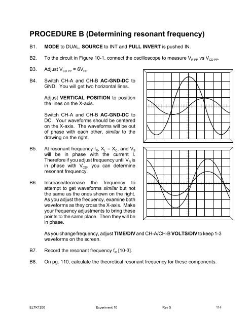
PROCEDURE B (Determining resonant frequency)B1. MODE to DUAL, SOURCE to INT and PULL INVERT is pushed IN.B2. To the circuit in Figure <strong>10</strong>-1, connect the oscilloscope to measure V R PP vs V CD PP .B3. Adjust V CD PP = 6V PP .B4. Switch CH-A and CH-B AC-GND-DC toGND. You will get two horizontal lines.Adjust VERTICAL POSITION to positionthe lines on the X-axis.Switch CH-A and CH-B AC-GND-DC toDC. Your waveforms should be centeredon the X-axis. The waveforms will be outof phase with each other, similar to thedrawing on the right.B5. At resonant frequency f R , X L = X C , and V Swill be in phase with the current I.Therefore if you adjust frequency until V R isin phase with V CD , you can determineresonant frequency.B6. Increase/decrease the frequency toattempt to get waveforms similar but notthe same as the ones shown on the right.As you adjust the frequency, examine bothwaveforms as they cross the X-axis. Makeyour frequency adjustments to bring thesepoints to the same place. Then they will bein phase.As you change frequency, adjust TIME/DIV and CH-A/CH-B VOLTS/DIV to keep 1-3waveforms on the screen.B7. Record the resonant frequency f R [<strong>10</strong>-3].B8. On pg. 1<strong>10</strong>, calculate the theoretical resonant frequency for these components.ELTK<strong>1200</strong> <strong>Experiment</strong> <strong>10</strong> Rev 5 114