CobraTig® 150 XM Owner's Manual - MK Products
CobraTig® 150 XM Owner's Manual - MK Products
CobraTig® 150 XM Owner's Manual - MK Products
You also want an ePaper? Increase the reach of your titles
YUMPU automatically turns print PDFs into web optimized ePapers that Google loves.
SAFETY CONSIDERATIONSELECTRIC ARC WELDING EQUIPMENTCAUTION : READ BEFORE ATTEMPTING INSTALLATION, OPERATIONOR MAINTENANCE OF THIS EQUIPMENT1-1 INTRODUCTIONThis equipment is intended for ultimateapplication by commercial/industrial usersand for operation by persons trained andexperienced in the use and maintenanceof welding equipment. Operation shouldnot be undertaken without adequate trainingin the use of such equipment. Trainingis available from many public and privateschools or similar facilities.Safe practices in the installation, operationand maintenance of this equipmentrequires proper training in the art, a carefulstudy of the information provided withthe equipment, and the use of commonsense. Rules for safe use are generallyprovided by suppliers of welding powersources, compressed gas suppliers, andelectrode suppliers. Careful compliancewith these rules will promote safe use ofthis equipment.The following Safety Rules cover someof the more generally found situations.READ THEM CAREFULLY. In case ofany doubt, obtain qualified help beforeproceeding.1-2 GENERAL PRECAU-TIONSA. Burn PreventionELECTRIC ARC WELDING PRODUCESHIGH INTENSITY HEAT AND ULTRAVI-OLET RADIANT ENERGY WHICH MAYCAUSE SERIOUS AND PERMANENTEYE DAMAGE AND WHICH MAY DAM-AGE ANY EXPOSED SKIN AREAS.Wear helmet with safety goggles orglasses with side shields underneath,appropriate filter lenses or plates (protectedby clear cover glass). This is amust for welding or cutting (and chipping)to protect the eyes from radiant energyand flying metal. Replace cover glasswhen broken, pitted, or spattered.Medical first aid and eye treatment.First aid facilities and a qualified first aidperson should be available for each shiftunless medical facilities are close by forimmediate treatment of flash burns of theeyes and skin burns.Wear protective clothing - leather (orasbestos) gauntlet gloves, hat, and highsafety-toe shoes. Button shirt collar andpocket flaps, and wear cuffless trousersto avoid entry of sparks and slag.Avoid oily or greasy clothing. A sparkmay ignite them.Flammable hair preparations should notbe used by persons intending to weldor cut.Hot metal such as electrode stubs andwork pieces should never be handledwithout gloves.Ear plugs should be worn when workingon overhead or in a confined space. Ahard hat should be worn when others workoverhead.B. Toxic Fume PreventionWARNING: The use of this product may resultin exposure to chemicals known to theState of California to cause cancer and birthdefects or other reproductive harm.Adequate ventilation. Severe discomfort, illnessor death can result from fumes, vapors,heat, or oxygen enrichment or depletion thatwelding (or cutting) may produce. Preventthem with adequate ventilation. NEVERventilate with oxygen.Lead-, cadmium-, zinc-, mercury-, berylliumbearingand similar materials, when weldedor cut, may produce harmful concentrationsof toxic fumes. Adequate local exhaust ventilationmust be used, or each person in thearea, as well as the operator, must wear anair-supplied respirator. For beryllium, bothmust be used.Metals coated with or containing materialsthat emit toxic fumes should not be heatedunless coating is removed form the worksurface, the area is well ventilated, or theoperator wears an air-supplied respirator.Work in a confined space only while it isbeing ventilated and, if necessary, whilewearing an air-supplied respirator.Gas leaks in a confined space should beavoided. Leaked gas in large quantities canchange oxygen concentration dangerously.Do not bring gas cylinders into a confinedspace.Leaving confined space, shut OFF gas supplyat source to prevent possible accumulationof gases in the space if downstreamvalves have been accidentally opened orleft open. Check to be sure that the spaceis safe before reentering it.Vapors from chlorinated solvents can be decomposedby the heat of the arc (or flame)to form PHOSGENE, a highly toxic gas,and other lung and eye irritating products.The ultraviolet (radiant) energy of the arccan also decompose trichloroethylene andperchloroethylene vapors to form phosgene.DO NOT WELD or cut where solvent vaporscan be drawn into the welding or cuttingatmosphere or where the radiant energycan penetrate to atmospheres containingeven minute amounts of trichloroethyleneor perchloroethylene.C. Fire and Explosion PreventionCauses of fire and explosion are: combustiblesreached by the arc, flame, flyingsparks, hot slag, or heated material, misuseof compressed gases and cylinders,and short circuits.BE AWARE THAT flying sparks or fallingslag can pass through cracks, alongpipes, through windows or doors, andthrough wall or floor openings, out ofsight of the goggled operator. Sparkscan fly many feet.To prevent fires and explosion:Keep equipment clean and operable, freeof oil, grease, and (in electrical parts) ofmetallic particles that can cause shortcircuits.If combustibles are in area, do NOT weldor cut. Move the work if practicable, toan area free of combustibles. Avoid paintspray rooms, dip tanks, storage areas,ventilators. If the work cannot be moved,move combustibles at least 35 feet away,out of reach of sparks and heat; or protectagainst ignition with suitable and snug-fitting,fire-resistant covers or shields.Walls touching combustibles on oppositesides should not be welded on (or cut).Walls, ceilings, and floor near workshould be protected by heat-resistantcovers or shields.Fire watcher must be standing by withsuitable fire extinguishing equipmentduring and for some time after weldingor cutting if:1. Appreciable combustibles (includingbuilding construction) are within35 feet.2. Appreciable combustibles are furtherthan 35 feet, but can be ignited bysparks.3. Openings (concealed or visible) infloors or walls within 35 feet may exposecombustibles to sparks.4. Combustibles adjacent to walls, ceilings,roofs, or metal partitions can beignited by radiant or conducted heat.Hot work permit should be obtainedbefore operation to ensure supervisor’sapproval that adequate precautions havebeen taken.After work is done, check that area is freeof sparks, glowing embers, and flames.An empty container that held combustibles,or that can produce flammable ortoxic vapors when heated, must neverbe welded on or cut, unless containerhas first been cleaned in accordance withindustry standards.This includes: a thorough steam orcaustic cleaning (or a solvent of water
THIS PAGE INTENTIONALLY BLANKCobraTig <strong>150</strong> <strong>Owner's</strong> <strong>Manual</strong> P/N 091-0541
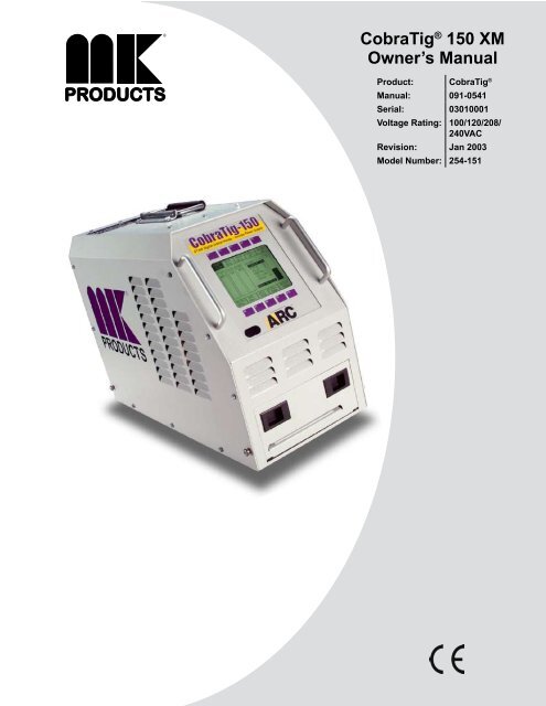
INTRODUCTIONThe portable, lightweight CobraTig® <strong>150</strong> <strong>XM</strong> with SmartArc®provides the automatic control you need to deliver repeatability,verification and traceability in high-integrity orbital and manualwelding.SmartArc® software develops a near ideal weld procedurethrough the use of our Automatic Procedure Generator. Justenter the tube outside diameter and wall thickness... The rest isautomatic.This version of CobraTig®Software and Hardware has the latestin Micro-Tig Technology. The system is now capable of goingdown to 0.1 amps. High Voltage Pulse automatic arc startingfrom 0.5 to 25 amps.Make the most of your offsite and onsite welding operations.With the CobraTig® <strong>150</strong> <strong>XM</strong>, you’ll weld circles around the competition.CobraTig <strong>150</strong> <strong>Owner's</strong> <strong>Manual</strong> P/N 091-0541 - Page
The order numbers for the twist-lock type are: P/N 153-0755 Electrode (maleconnector to exchange for the black connector) and P/N 153-0813 Ground(female connector to exchange for the green connector).For MicroTig welding operations, the MicroTig Accessory Kit (P/N 005-0670)is also available. This contains all the necessary items needed when usingthe CobraTig®<strong>150</strong> <strong>XM</strong> unit in the WELD MANUAL mode.Precision MicroTig Technology is a standard feature of the CobraTig®<strong>150</strong><strong>XM</strong>. The ideal precision manual welder produces reliable, smooth arc startsat 0.5 amps and is perfect for welding precision thin wall exotic materialssuch as titanium and stainless steel or fine wire sizes.Section 4ConnectionsInput PowerThe CobraTig® <strong>150</strong> <strong>XM</strong> can operate on any of four different input power values:100VAC, 120VAC, 208/230VAC Single Phase and, 208/230VAC ThreePhase. Attached to the unit is a 12ft power cable that comes wired fromthe factory ready for 120VAC. Even though the installed plug is only threeprongs, there are four wires in the cable, ready for three phase power.DANGERDISCONNECT ALL POWER TO THE UNIT PRIOR TO CHANGING THE POWERTAPS. FAILURE TO DO THIS WILL RESULT IN SERIOUS BODILY HARM ANDEXTENSIVE EQUIPMENT DAMAGE.To change the input power type, three changes have to be made to the CobraTig®<strong>150</strong> <strong>XM</strong> unit: first change the voltage jumper, then the voltage selectorcable and the plug on the end of the cable. You will need a 1/4” nutdriverwrench and a #2 Phillips head screwdriver.Using the nutdriver, remove all the 1/4” hex head screws from the cover ofthe unit, then lift the cover off. Locate TB1 on the lower-right-rear side of theunit, from the front. Using the Phillips head screwdriver to change the taps,follow the directions below:Configure Voltage Selector Jumper at TB1 terminals 1-3, for the inputvoltage, 100V/120V or 208V/230V. Remove and flip over to change (seeJumper Configuration image).CobraTig <strong>150</strong> <strong>Owner's</strong> <strong>Manual</strong> P/N 091-0541 - Page 11
100/120V208/230V100V 120V 208V 230V100V 120V 208V 230V1 2 3 4 5 6 7 8TB1 Configuredfor 100/120VAC1 2 3 4 5 6 7 8TB1 Configuredfor 208/230VACJumper ConfigurationMove “Voltage Selector Cable” to the corresponding input voltage terminal ofTB1 for 100V, 120V, 208V, or 230V.After the input voltage taps have been configured, then change the plug onthe end of the power cable to match.SmartArc® Software UpdateWhen viewing the MAIN MENU of the CobraTig® <strong>150</strong> <strong>XM</strong>, the currentlyloaded software version will appear across the middle of the screen. Oncethe software update is properly performed, this version number will show thenewly loaded version number.In order to update the SmartArc® software in the CobraTig® <strong>150</strong> <strong>XM</strong>, the followingitems are needed:• CobraTig® <strong>150</strong> <strong>XM</strong>• PC running DOS• RS-232 serial cable/null modem wiring (female connector both ends)• Diskette with UPDAT<strong>150</strong>.exe and UPGRADE.<strong>150</strong> filesThe SmartArc® software updating procedure is as follows:1. Connect the RS-232 serial cable between the PC (9 or 25 pin - wheremouse usually connects) and the rear panel of the CobraTig® <strong>150</strong> <strong>XM</strong> (9pin).2. Simultaneously while pressing the F10 button (lower-right hand button)on the CobraTig® <strong>150</strong> <strong>XM</strong> front panel, turn on the CobraTig® <strong>150</strong> <strong>XM</strong>.The screen should display a “READY TO RECEIVE…” prompt, as shownCobraTig <strong>150</strong> <strong>Owner's</strong> <strong>Manual</strong> P/N 091-0417 - Page 12
elow. If it does not, turn CobraTig® <strong>150</strong> <strong>XM</strong> off and try again.3. On the PC, while running DOS insert the diskette and change to driveA:\. Type UPDAT<strong>150</strong>.EXE and press ENTER.When prompted, type in the port number (see PC owner’s manual).4. Once the upgrading program starts, the screen on the CobraTig® <strong>150</strong><strong>XM</strong> will show the status of the downloading. Once complete, turn off theCobraTig® <strong>150</strong> <strong>XM</strong> and disconnect RS-232 serial cable.5. Restart the CobraTig® <strong>150</strong> and view the MAIN MENU to inspect for thenew SmartArc® software version number.Section 5OPERATIONTo operate the CobraTig® <strong>150</strong> <strong>XM</strong> portable orbital welding unit, plug in anystandard <strong>MK</strong> Orbital weldhead to the rear panel, and perform the basic setupprocedures associated with collets, tungsten, and concentricity. Plug the CobraTig®<strong>150</strong> <strong>XM</strong> into any 120VAC electrical outlet (independent and isolatedcircuits will produce the best results), connect the quick disconnect gas fittinginto the unit, and the other end to any argon flowmeter.Power the unit on by rocking the ON/OFF switch to the ON position (locatedON/OFFWeldhead GasWeldheadConnectionsAmphenolConnectorElectrodeRS232Input GasGroundInput PowerCableCobraTig <strong>150</strong> <strong>Owner's</strong> <strong>Manual</strong> P/N 091-0541 - Page 13
on the rear panel - see below). The unit will remember the last screen thatwas on when it was powered off. To start from the beginning, it is best tocalibrate the weldhead prior to starting. Once the weldhead is calibrated,press any button that will return the screen to the MAIN MENU.From this point use the AUTO PROG button to start designing the weld procedure,enter the appropriate variables for the material to be welded, prepareand align material to be welded, check for proper purge gas flow... PressSTART.The CobraTig® <strong>150</strong> <strong>XM</strong> unit will automatically prepurge the gas flow, initiatethe welding arc, perform any tacks if so desired, complete the weld in one ormultiple revolutions depending on procedure design and return the rotor tohome position while the postpurge gas is flowing. Weld complete.Weldhead ConnectorRS-232 Data ConnectorThe CobraTig®uses a DB-9 connector to communicate with an External PC.The wiring for this plug is “cable/null” modem wiring (female connector bothends).Section 6Main MenuCobraTig <strong>150</strong> <strong>Owner's</strong> <strong>Manual</strong> P/N 091-0417 - Page 14
This is the starting menu for the CobraTig® <strong>150</strong> <strong>XM</strong> orbital welder. It is fromthis menu that all the other menu displays and screens are accessible. Fromeach menu display, there is a one-step button back to this menu.This is not to say that every time this unit is turned on that it will start at thisscreen. The operating program is such that it will remember the last screenwhen the unit is turned off. When the unit is turned on again, it will start withthe last screen displayed.Help (Defines the Main Menu button selections)Press this button to read a brief description of the MAIN MENU button descriptionsand functions.Section 7Weld <strong>Manual</strong>From the MAIN MENU screen, the WELD MANUAL button must be pressedin order to access the WELD MANUAL screen.User Interface Programming Sequence· From the Main Menu.· Press F2 Weld <strong>Manual</strong>, permits manual welding.· Press F7 and enter Pedal On, permits use of foot control for weldcurrent Upslope and Final slope control and continuouswelding.· Press F7 and enter Pedal Off, permits use of ON/OFF switch withprogrammable weld current upslope and final slope times from0.00~1.0 seconds each.· Press F4 or F9 and scroll to Curr. H. (A), high weld current in amps.CobraTig <strong>150</strong> <strong>Owner's</strong> <strong>Manual</strong> P/N 091-0541 - Page 15
Note: The Current High Amps establishes the maximum output inamps that may be obtained.· Press F5 or F10 and enter High current value from 0.2~<strong>150</strong> amps.· Press F4 or F9 and scroll to Curr. L. (A), low weld current in amps.· Press F5 or F10 and enter Low current value from 0.2~<strong>150</strong> amps.· Press F4 or F9 and scroll to Pulse H. (S), high weld current pulsetime.· Press F5 or F10 and enter High weld current pulse time from0.00~0.99 seconds.· Press F4 or F9 and scroll to Pulse L. (S), low weld current pulsetime.· Press F5 or F10 and enter Low weld current pulse time from0.00~0.99 seconds.· Press F4 or F9 and scroll to Pre-Gas (S), pre-purge gas time.· Press F5 or F10 and enter pre-purge gas time from 0.0~9.9 seconds.· Press F4 or F9 and scroll to Post-Gas (S), post-purge gas time.· Press F5 or F10 and enter post-purge gas time from 0.0~9.9seconds.· Press F4 or F9 and scroll to Strike (A), arc strike weld current.· Press F5 or F10 and enter arc strike weld current from 0.1~25.0amps.· Press Foot Control to maximum and hold for duration of weld· Press F6 Print Weld wave form graphics from integral printerWELD MANUAL SCREEN DISPLAY· F1, Start/Stop, used for manual Start/Stop operations without a footcontrol.· F2, Main Menu, returns to the Main Menu display.· F3, Weld Orbital, returns to the Weld Orbital display.· F4, Scroll UP, scrolls the highlighted field from one demandparameter to the next demand parameter.· F5, Adjust Up, increases the numerical value of the demandparameter selected. As this button is pressed for each parameter avertical bar graph displays the increasing value, both numerically andgraphically from the bar graph. For most parameters, a maximumvalue is obtained once the vertical bar graph has reached the top ofthe scale. Also, there is a change in the sound once the top of thescale has been reached. The sound changes from a single beep to atriple beep.· F6, Print Weld, Data-Monitoring of manual weld produces a graphicalreal time wave form of welding amps and arc volts.· F7, Pedal On, selects the variable remote foot control for operation.· F7, Pedal Off, selects the On/Off switch control and permitsadditional programming of weld current Upslope time in seconds andFinal Slope weld current time in seconds.· F8, Blank, no function control.· F9, Scroll Down, scrolls the highlighted field from one demandparameter to the next demand parameter.· F10, Adjust Down, decreases the numerical value of the demandparameter selected. As this button is pressed for each parameter avertical bar graph displays the decreasing value, both numericallyand graphically from the bar graph. For most parameters, a minimumvalue is obtained once the vertical bar graph has reached the bottomof the scale. Also, there is a change in the sound once the bottom ofthe scale has been reached. The sound changes from a single beepto a triple beep.Section 8Weld OrbitalCobraTig <strong>150</strong> <strong>Owner's</strong> <strong>Manual</strong> P/N 091-0417 - Page 16
From the MAIN MENU screen press this button to select orbital welding.Once at the WELD ORBITAL screen, use the RECALL PROGRAM buttonat the bottom of the screen to select from the library of customer designedand saved procedures, or return to the MAIN MENU and use the APG (AutoProcedure Generation) function in order to design a new weld procedure.Use the SCROLL UP, SCROLL DOWN, ADJUST UP, and ADJUST DOWNbuttons to select and modify specific weld procedure parameters. Thenwhen all variables are set, press the START/STOP button to initiate the weldingprocess.Once at the WELD ORBITAL screen, the last orbital weld procedure is displayedfrom memory. This is the default procedure and ready to weld. If adifferent weld procedure is desired, it can either be recalled from memory or,developed using the Auto Program Generator (APG).Start/StopPressing this button will start the prepurge gas flowing and start the weldingprocedure.Main MenuPress this button to return to the MAIN MENU.Print WeldPress the PRINT WELD button to obtain a printout of the last weld procedureparameters and the wave form strip chart of the completed weld.This will give a weld procedure printout, first showing the description ofthe procedure, followed by the all the welding parameters, then by Limitand Deviation parameters, then by the actual strip chart of the weld current,arc voltage and motor speed.Scroll UpPress this button in order to scroll and select the highlighted field fromone DEMAND parameter up to the next.Adjust UpAfter the SCROLL UP or SCROLL DOWN buttons have been used toselect a parameter to be modified, press the ADJUST UP button to increasethe numerical value of that parameter.As this button is pressed for each parameter a vertical bar graph showsthe increasing value, both numerically and in height of the bar graph.For most parameters, a maximum value is obtained once the vertical barCobraTig <strong>150</strong> <strong>Owner's</strong> <strong>Manual</strong> P/N 091-0541 - Page 17
graph has reached the top of the scale. There is also a change in thesound once the maximum has been reached, from a single ‘beep’ to atriple ‘beep’.Section 9Recall ProgramPress the RECALL PROGRAM in order to access the library of operatorsaved weld procedures.NOTE: If the currently used procedure is not saved, a warning screenof text will prompt for a ‘YES’ or ‘NO’ answer: this is the OVERWRITEscreen. Anytime there is a potential change to the existing weld procedure,this screen will appear.If ‘NO’ is pressed, the screen will return to the WELD ORBITAL screen.If ‘YES’ is pressed, the screen will change to RECALL USER MEMORY.HelpPress this button to read a brief description of the RECALL menubutton descriptions and functions.Main MenuPress this button to return to the MAIN MENU.Weld OrbitalPress this button to return to the WELD ORBITAL screen.Scroll LeftEach time this button is pressed, the locations of where each weldprocedure is saved will move three number locations to the left.LocationsCobraTig <strong>150</strong> <strong>Owner's</strong> <strong>Manual</strong> P/N 091-0417 - Page 18
The bottom three buttons on this screen indicate the number of thelocation where weld procedures are saved. Using the SCROLLLEFT and SCROLL RIGHT button, will move the locations accordinglyto show the status of each location.Those locations with the word EMPTY above the number, indicatethat there is no weld procedure saved in that location.Scroll RightEach time this button is pressed, the locations of where each weldprocedure is saved will move three number locations to the right.Those locations with the word EMPTY above the number, indicatethat there is no weld procedure saved in that location.If the current weld program is a temporary, unsaved/modified program, theRECALL screen will be blank. This indicates that the current weld programhas not been saved to any location. However, if the current weld program isfrom one of the saved locations, this screen will display the location it is presentlysaved at.Press any button that does not contain the word EMPTY. Press WELDORBITAL to return to that screen to begin welding with the saved procedure.Section 10Save ProgramOnce a weld procedure has been developed, it is generally a good ideato save it for use at a later date. In order to do this, simply press theSAVE PROGRAM button. This will change to the SAVE USER MEMO-RY screen.HelpPress this button to read a brief description of the SAVE menu buttondescriptions and functions.Main MenuPress this button to change to the MAIN MENU.Weld OrbitalPress this button to change to the WELD ORBITAL screen.Communication MenuPress this button to change to the COMMUNICATION MENU.Scroll LeftCobraTig <strong>150</strong> <strong>Owner's</strong> <strong>Manual</strong> P/N 091-0541 - Page 19
Each time this button is pressed, the locations of where each weldprocedure is saved or can be saved to, will move three numbers tothe left.Those locations with the word EMPTY above the number, indicatethat there is no weld procedure saved in that location.LocationsWhen a location button is pressed, and if that location is alreadyoccupied with a weld procedure, another screen will appear with anOVERWRITE VERIFY message.If the current procedure is to be saved at this location, press “YES”.If this location is to be emptied, and the saved weld procedureerased, press “EMPTY ONLY”. If nothing is to be done with thislocation, and you need to return to the SAVE PROGRAM MENU,press “NO”.Scroll RightEach time this button is pressed, the locations of where each weldprocedure is saved or can be saved to, will move three numbers tothe right.Those locations with the word EMPTY above the number, indicatethat there is no weld procedure saved in that location.Weld ModeCobraTig <strong>150</strong> <strong>Owner's</strong> <strong>Manual</strong> P/N 091-0417 - Page 20
Pressing this button will toggle the high voltage arc starter from theprompt READY TO WELD (high voltage enabled) to READY TO TEST(high voltage disabled). This toggle is visible at the bottom of the WELDORBITAL screen.Scroll DownPress this button in order to scroll the highlighted field from one DE-MAND parameter down to the next. Adjustment of each parameter isperformed using the ADJUST UP or ADJUST DOWN buttons.Adjust DownAfter the SCROLL UP or SCROLL DOWN buttons have been used toselect a parameter to be modified, press the ADJUST DOWN button todecrease the numerical value of that parameter.As this button is pressed for each parameter a vertical bar graph showsthe decreasing value, both numerically and in height of the bar graph.For most parameters, a minimum value is obtained once the vertical bargraph has reached the bottom of the scale. There is also a change inthe sound once the minimum has been reached, from a single ‘beep’ to atriple ‘beep’.Section 11Auto Program GeneratorFrom the main menu screen press Auto Prog. The ease of using the CobraTig®<strong>150</strong> <strong>XM</strong> comes primarily from this feature. By simply inputting somebasic tube or pipe variables, the CobraTig® <strong>150</strong> <strong>XM</strong> digital controller cangenerate and produce a near ideal weld procedure.The following menu will guide the operator through basic fields of informationentry. Beginning with selections for tube or pipe and diameter and wall thickness.Additional information can be designed into the procedure that includedifferent pulse types, up to 5.0 seconds motor delay time, multiple revolutions,and programming of up to 7 opposing tacks.HelpPress this button to read a brief description of the APG button descriptionsand functions.Ignore EntriesPressing this button at any time during the design of a weld procedure,will automatically return the program to the MAIN MENU and lose allentered information.CobraTig <strong>150</strong> <strong>Owner's</strong> <strong>Manual</strong> P/N 091-0541 - Page 21
Accept EntriesOnce the first three variables are entered into the APG screen this buttonmay be pressed, thus bypassing any additional features and changingdirectly to the WELD ORBITAL screen.Previous EntryPress this button to return to the previous field in order to change theentered value.Next EntryPress this button to jump to the next field in order to change the enteredvalue or add a new value.Gas On/Gas OffThis button is used to manually toggle the gas flow either “ON” OR“OFF”. This button is used to indicated the status of the gas flow.When the button reads “GAS ON”, the gas solenoid valve is open andthe gas flowing.When the button reads “GAS OFF”, the gas solenoid valve is closed andthe gas is not flowing.Section 12Print MenuAt the PRINT MENU, many different aspects of the CobraTig® <strong>150</strong> <strong>XM</strong> canbe printed or modified. Not only can various printouts of weld procedures, listof procedures, and calibration reports be made but the printer configurationcan be modified to print on command or automatically.HelpPress this button to read a brief description of the PRINT MENU buttondescriptions and functions.Main MenuPress this button to return to the MAIN MENU.Print GraphThis function works with the Printer After Welds function. Pressing thisbutton toggles the command from YES (prints weld procedure parametersplus entire weld graph), to NO (prints weld procedure parametersonly).CobraTig <strong>150</strong> <strong>Owner's</strong> <strong>Manual</strong> P/N 091-0417 - Page 22
Paper FeedPress and hold this button down in order to feed paper through theprinter driver mechanism. This is especially useful after loading a newroll of paper.Printer ResetShould the printer run out of paper either during a PRINT WELD or whilefeeding, the PRINTER STATUS field will read as follows, “Error, PrinterError.”.Once a new roll of paper has been loaded and fed through using thePRINTER FEED button, press the PRINTER RESET button once. Thisshould return the PRINTER STATUS field to read, “OK”.To load a new roll of paper, slide printer tray straight out until it stops.Disengage the Printer Drive Mechanism by pulling down the DriveLatch Arm on the left side of the printer. Unroll approximately 4 to6 inches of paper from the roll and insert between the Printer DriveMechanism and the bottom platen, push the paper through until itemerges from the front panel of the printer tray.Drive Latch ArmInsert roll of paper between pins and spin backward to pull up anyextra slack in the paper. Engage the Drive Latch Arm upward tosecure the Printer Drive Mechanism.Driver MechanismBottom PlatenCobraTig <strong>150</strong> <strong>Owner's</strong> <strong>Manual</strong> P/N 091-0541 - Page 23
Press the PRINTER FEED button to align paper in Drive, then pressthe PRINTER RESET button.Active ProgramPress this button in order to print the current weld procedure that isloaded on the memory of the unit.Last Orbital WeldPress this button to obtain a printout of the last completed orbital weld.This will give the same results as the PRINT WELD button on the WELDORBITAL screen.This will give a weld procedure printout, first showing the description ofthe procedure, followed by the all the welding parameters, then by Limitand Deviation parameters, then by the actual strip chart of the weld amperage,arc voltage and motor speed.Program ListPress this button to printout the complete listing of all the weld proceduressaved in the memory of the unit.Calibration ReportTo obtain a printout of the calibration values for the motor, motor-tachometerfeedback, current and voltage scales, press this button.Print OptionThis button controls the Deviation Report printout after each weld. Thereare only three options available for this printout, they are as follows:NEVER, ALWAYS & FAULTS.In the NEVER mode, a printout of the weld will only occur if thePRINT WELD button is pressed.In the ALWAYS mode, at the end of every weld once the rotor returnsto the home position, it will automatically printout the resultant StripChart as if the PRINT WELD button had been pressed.In the FAULTS mode, a Strip Chart will only printout if there weredeviations in the weld sequence.Section 13Calibration MenuPrior to using the CobraTig® <strong>150</strong> <strong>XM</strong> unit for welding, it is generally a goodidea to calibrate the output and feedback readings prior to striking an arc.CobraTig <strong>150</strong> <strong>Owner's</strong> <strong>Manual</strong> P/N 091-0417 - Page 24
This screen will allow the operator to calibrate any orbital weldhead,at any speed value, between 1.0 and 10.0 rpm. Using the HIGH/LOWbutton, select the respective speed value and use the ADJUST UP andADJUST DOWN buttons to select the rpm value required.The HIGH and LOW values can never be equal. A minimum of 1.0 rpmwill separate the two values. If the LOW value is increased, the HIGHwill increase, with the 1.0 rpm difference between them. Similarly, if theHIGH is decreased, the LOW will decrease with the 1.0 rpm difference.Feedback of the weldhead during calibration is seen in the bar graph onthe left side of this screen.High/LowToggles between the HIGH and LOW rpm speed values.Print ReportPress this button, once calibration is complete, to view a printed report ofthe calibration values.The calibration values shown are an indication of the MOTOR/TACHstatus of the weldhead. A typical printout is shown below:MOTOR Calibration reportMOTOR gain: -4.6% Zero offset: 0.30 RPMTACH gain: 1.9% Zero offset: 0.02 RPMShould these MOTOR & TACH values return with number of 0.00% and0.00 RPM, the calibration was invalid and should be re-run. Continuousresults of all zeros, is an indication that the weldhead is in need ofservice.Consult the weldhead owner’s manual for proper maintenance and calibrationservice.MOTOR Calibration reportMOTOR gain: 0.0% Zero offset: 0.00 RPMTACH gain: 0.0% Zero offset: 0.00 RPMNOTE: If all values for MOTOR or WELDER calibration are zeros, itmeans that he calibration did not complete successfully and is not valid.Start CalibrationPress this button to start the weldhead calibration procedure. The calibrationstart at the values selected using the “ADJUST UP” and “AD-JUST DOWN” buttons.Current StartUsing the calibration kit and the multimeter, calibration of the output currentcan be achieved in relatively short time. Using the 10 A CALIBRA-TION and 80 A CALIBRATION buttons, output values at these points willproperly calibrate the current for almost all applications.10A Calibration / 80A CalibrationThese two keys are used in conjunction for calibrating the output current.Use the information on the HELP screen to perform this calibrationprocedure.CobraTig <strong>150</strong> <strong>Owner's</strong> <strong>Manual</strong> P/N 091-0417 - Page 26
Connect the multimeter to the shunt labelled CURRENT, set the tungstenarc gap and the gas setting and press CURRENT START. Once the 10A arc is established, use the ADJUST UP and ADJUST DOWN buttonsto reach 2.50 mV on the multimeter. Once this mV value is read, pressthe 10 A button, this will automatically jump the current to the 80 A outputvalue.Use the UP and DOWN buttons to set the mV value to 20.0 mV, thenpress 80 A. This cycle will repeat once more then quit when ready.Once the arc is extinguished, the output current has been calibrated.Adjust DownPress this button to adjust the bar graph setting to match that of the referencevalue being read - voltage or current.Section 14Communication MenuIt is from this screen that weld procedures can be transferred from oneCobraTig® <strong>150</strong> <strong>XM</strong> unit to another. There are two paths available for transmission:IR (Infra Red) and Wired Cable. The IR method works much like aTV remote, just have the two units facing each other at a distance up to 10feet and commence transmitting. While the Wired Cable is a cable hookupbetween the units’ RS232 transmission ports on the rear panels.HelpPress this button to read a brief description of the CALIBRATION MENUbutton descriptions and functions.Main MenuPress this button to return to the MAIN MENU.Save MenuPress this button to change to the SAVE MENU.Xmit ChannelThis button will toggle between two choices of transmission. Either InfraRed or Wired Cable.Start ReceiveTo begin transmitting a procedure to another machine, press this button.Scroll LeftEach time this button is pressed, the locations of where each weld procedureis saved or can be saved to, will move three numbers to the left.CobraTig <strong>150</strong> <strong>Owner's</strong> <strong>Manual</strong> P/N 091-0541 - Page 27
Those locations with the word EMPTY above the number, indicate thatthere is no weld procedure saved in that location.LocationsIn order to transmit a procedure, first locate the location number of wherethe procedure is saved. Then press the applicable button to send. TheSTART RECEIVE button will then toggle to show STOP <strong>XM</strong>IT, promptingthe operator to cancel the transmission when pressed.On the receiving unit, simply press the START RECEIVE button to savedthe transmitting procedure, then press the location number of where theprocedure is to be saved. If the procedure is saved to a location that isempty, the EMPTY label will disappear once the procedure is saved.Scroll RightEach time this button is pressed, the locations of where each weld procedureis saved or can be saved to, will move three numbers to the right.Those locations with the word EMPTY above the number, indicate thatthere is no weld procedure saved in that location.Section 15Setup MenuThis menu is used to set up the user’s preferences of the weld procedureserialization, button clicks and sounds, and LCD display contrast.HelpPress this button to read a brief description of the SETUP MENU buttondescriptions and functions.Main MenuPress this button to change to the MAIN MENU.Decrease S/NThis button will DECREASE the starting serial number of the next orbitalweld. The serial number is incremented before every weld, so use onenumber less than actual number of next weld.Increase S/NThis button will INCREASE the starting serial number of the next orbitalweld. The serial number is incremented before every weld, so use onenumber less than actual number of next weld.CobraTig <strong>150</strong> <strong>Owner's</strong> <strong>Manual</strong> P/N 091-0417 - Page 28
Higher ContrastPress this button to increase the contrast for the LCD screen. This willmake the display darker as the number increases.Change UnitsPress this button to toggle units from INCHES to METRIC. It will only affectthe screen display when using AUTO PROCEDURE GENERATION,see MAIN MENU.Change SoundPress this button to enable or disable sound.Change ClickPress this button to enable or disable button clicks.Change LightThis toggles the LCD backlight either ON or OFF. The AUTO setting willsense ambient light and change the backlight to adjust accordingly.Lower ContrastPress this button to decrease the contrast for the LCD screen. This willmake the display lighter as the number decreases.Section 16Diagnostic MenuThis screen will show the units internal total on-time diagnostics. This includesnumber of times unit was powered on, the total on-time, the numberof welds performed, total arc time and number of times a weld procedure wassaved.HelpPress this button to read a brief description of the DIAGNOSTIC MENUbutton descriptions and functions.Main MenuPress this button to return to the MAIN MENU.CobraTig <strong>150</strong> <strong>Owner's</strong> <strong>Manual</strong> P/N 091-0541 - Page 29
THIS PAGE INTENTIONALLY BLANKCobraTig <strong>150</strong> <strong>Owner's</strong> <strong>Manual</strong> P/N 091-0541
3 YEARLIMITED WARRANTYEffective February 1, 2003This warranty supersedes all previous <strong>MK</strong> <strong>Products</strong> warranties and isexclusive, with no other guarantees or warranties expressed or implied.LIMITED WARRANTY - <strong>MK</strong> <strong>Products</strong>,Inc.,Irvine,Californiawarrants that all new and unused equipment furnished by <strong>MK</strong><strong>Products</strong> is free from defects in workmanship and material asof the time and place of delivery by <strong>MK</strong> <strong>Products</strong>. No warrantyis made by <strong>MK</strong> <strong>Products</strong> with respect to trade accessories orother items manufactured by others. Such trade accessories andother items are sold subject to the warranties of their respectivemanufacturers, if any.<strong>MK</strong> <strong>Products</strong>’ warranty does not apply to components havingnormal useful life of less than one (1) year, such as relay points,wire conduit, tungsten, and welding torch parts that come incontact with the welding wire, including gas cups, gas cup insulators,and contact tips where failure does not result from defectin workmanship or material.<strong>MK</strong> <strong>Products</strong>’ shall, exclusively remedy the limited warrantyor any duties with respect to the quality of goods, based uponthe following options:(1) repair(2) replacement(3) where authorized in writing by <strong>MK</strong> <strong>Products</strong>, the reasonablecost of repair or replacement at our Irvine, California plant; or(4) payment of or credit for the purchase price (less reasonabledepreciation based upon actual use) upon return of the goods atcustomer’s risk and expense. Upon receipt of notice of apparentdefect or failure, <strong>MK</strong> <strong>Products</strong> shall instruct the claimant on thewarranty claim procedures to be followed.As a matter of general policy only, <strong>MK</strong> <strong>Products</strong> may honor anoriginal user’s warranty claims on warranted equipment in theevent of failure resulting from a defect within the following periodsfrom the date of delivery of equipment to the original user:1. Torches, Weldheads & Water Recirculators................................ 1 year2. All Other Equipment...................................................................3 years3. Repairs ......................................................................................90 daysClassification of any item into the foregoing categories shall beat the sole discretion of <strong>MK</strong> <strong>Products</strong>. Notification of any failuremust be made in writing within 30 days of such failure.A copy of the invoice showing the date of sale must accompanyproducts returned for warranty repair or replacement.All equipment returned to <strong>MK</strong> <strong>Products</strong> for service must beproperly packaged to guard against damage from shipping.<strong>MK</strong> <strong>Products</strong> will not be responsible for any damages resultingfrom shipping.Normal surface transportation charges (both ways) for productsreturned for warranty repair or replacement will be borne by <strong>MK</strong><strong>Products</strong>, except for products sold to foreign markets.ANY EXPRESS WARRANTY NOT PROVIDED HEREIN AND ANYIMPLIED WARRANTY, GUARANTY, OR REPRESENTATION AS TOPERFORMANCE, AND ANY REMEDY FOR BREACH OF CONTRACTWHICH, BUT FOR THIS PROVISION, MIGHT ARISE BY IMPLICA-TION, OPERATION OF LAW, CUSTOM OF TRADE, OR COURSEOF DEALING, INCLUDING ANY IMPLIED WARRANTY OF MER-CHANTABILITY OR OF FITNESS FOR PARTICULAR PURPOSE,WITH RESPECT TO ANY AND ALL EQUIPMENT FURNISHEDBY <strong>MK</strong> PRODUCTS, IS EXCLUDED AND DISCLAIMED BY <strong>MK</strong>PRODUCTS.EXCEPT AS EXPRESSLY PROVIDED BY <strong>MK</strong> PRODUCTS IN WRIT-ING, <strong>MK</strong> PRODUCTS ARE INTENDED FOR ULTIMATE PURCHASEBY COMMERCIAL/INDUSTRIAL USERS AND FOR OPERATION BYPERSONS TRAINED AND EXPERIENCED IN THE USE AND MAIN-TENANCE OF WELDING EQUIPMENT AND NOT FOR CONSUMERSOR CONSUMER USE. <strong>MK</strong> PRODUCTS WARRANTIES DO NOTEXTEND TO, AND NO RE-SELLER IS AUTHORIZED TO EXTEND<strong>MK</strong> PRODUCTS’ WARRANTIES TO ANY CONSUMER.USE OF OTHER THAN GENUINE <strong>MK</strong> PRODUCTS’CONSUMABLES, parts, and accessories may invalidateyour product warranty.16882 Armstrong Ave.Irvine, CA 92606Tel (949)863-1234Fax (949)474-1428www.mkproducts.comDATE: February1, 2003CobraTig <strong>150</strong> <strong>Owner's</strong> <strong>Manual</strong> P/N 091-0541
<strong>MK</strong> PRODUCTS, INC.16882 ARMSTRONG AVE.IRVINE,CALIFORNIA 92606TEL (949) 863-1234 FAX (949) 474-1428


