Note: The Current High Amps establishes the maximum output inamps that may be obtained.· Press F5 or F10 and enter High current value from 0.2~<strong>150</strong> amps.· Press F4 or F9 and scroll to Curr. L. (A), low weld current in amps.· Press F5 or F10 and enter Low current value from 0.2~<strong>150</strong> amps.· Press F4 or F9 and scroll to Pulse H. (S), high weld current pulsetime.· Press F5 or F10 and enter High weld current pulse time from0.00~0.99 seconds.· Press F4 or F9 and scroll to Pulse L. (S), low weld current pulsetime.· Press F5 or F10 and enter Low weld current pulse time from0.00~0.99 seconds.· Press F4 or F9 and scroll to Pre-Gas (S), pre-purge gas time.· Press F5 or F10 and enter pre-purge gas time from 0.0~9.9 seconds.· Press F4 or F9 and scroll to Post-Gas (S), post-purge gas time.· Press F5 or F10 and enter post-purge gas time from 0.0~9.9seconds.· Press F4 or F9 and scroll to Strike (A), arc strike weld current.· Press F5 or F10 and enter arc strike weld current from 0.1~25.0amps.· Press Foot Control to maximum and hold for duration of weld· Press F6 Print Weld wave form graphics from integral printerWELD MANUAL SCREEN DISPLAY· F1, Start/Stop, used for manual Start/Stop operations without a footcontrol.· F2, Main Menu, returns to the Main Menu display.· F3, Weld Orbital, returns to the Weld Orbital display.· F4, Scroll UP, scrolls the highlighted field from one demandparameter to the next demand parameter.· F5, Adjust Up, increases the numerical value of the demandparameter selected. As this button is pressed for each parameter avertical bar graph displays the increasing value, both numerically andgraphically from the bar graph. For most parameters, a maximumvalue is obtained once the vertical bar graph has reached the top ofthe scale. Also, there is a change in the sound once the top of thescale has been reached. The sound changes from a single beep to atriple beep.· F6, Print Weld, Data-Monitoring of manual weld produces a graphicalreal time wave form of welding amps and arc volts.· F7, Pedal On, selects the variable remote foot control for operation.· F7, Pedal Off, selects the On/Off switch control and permitsadditional programming of weld current Upslope time in seconds andFinal Slope weld current time in seconds.· F8, Blank, no function control.· F9, Scroll Down, scrolls the highlighted field from one demandparameter to the next demand parameter.· F10, Adjust Down, decreases the numerical value of the demandparameter selected. As this button is pressed for each parameter avertical bar graph displays the decreasing value, both numericallyand graphically from the bar graph. For most parameters, a minimumvalue is obtained once the vertical bar graph has reached the bottomof the scale. Also, there is a change in the sound once the bottom ofthe scale has been reached. The sound changes from a single beepto a triple beep.Section 8Weld OrbitalCobraTig <strong>150</strong> <strong>Owner's</strong> <strong>Manual</strong> P/N 091-0417 - Page 16
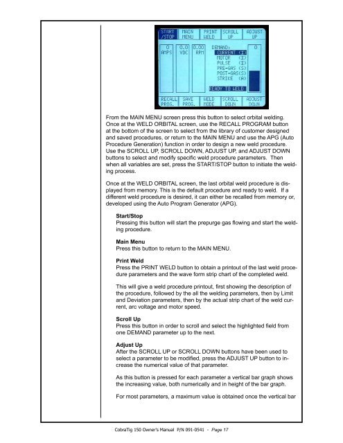
From the MAIN MENU screen press this button to select orbital welding.Once at the WELD ORBITAL screen, use the RECALL PROGRAM buttonat the bottom of the screen to select from the library of customer designedand saved procedures, or return to the MAIN MENU and use the APG (AutoProcedure Generation) function in order to design a new weld procedure.Use the SCROLL UP, SCROLL DOWN, ADJUST UP, and ADJUST DOWNbuttons to select and modify specific weld procedure parameters. Thenwhen all variables are set, press the START/STOP button to initiate the weldingprocess.Once at the WELD ORBITAL screen, the last orbital weld procedure is displayedfrom memory. This is the default procedure and ready to weld. If adifferent weld procedure is desired, it can either be recalled from memory or,developed using the Auto Program Generator (APG).Start/StopPressing this button will start the prepurge gas flowing and start the weldingprocedure.Main MenuPress this button to return to the MAIN MENU.Print WeldPress the PRINT WELD button to obtain a printout of the last weld procedureparameters and the wave form strip chart of the completed weld.This will give a weld procedure printout, first showing the description ofthe procedure, followed by the all the welding parameters, then by Limitand Deviation parameters, then by the actual strip chart of the weld current,arc voltage and motor speed.Scroll UpPress this button in order to scroll and select the highlighted field fromone DEMAND parameter up to the next.Adjust UpAfter the SCROLL UP or SCROLL DOWN buttons have been used toselect a parameter to be modified, press the ADJUST UP button to increasethe numerical value of that parameter.As this button is pressed for each parameter a vertical bar graph showsthe increasing value, both numerically and in height of the bar graph.For most parameters, a maximum value is obtained once the vertical barCobraTig <strong>150</strong> <strong>Owner's</strong> <strong>Manual</strong> P/N 091-0541 - Page 17