INSTRUCTION MANUAL
INSTRUCTION MANUAL
INSTRUCTION MANUAL

Create successful ePaper yourself
Turn your PDF publications into a flip-book with our unique Google optimized e-Paper software.
<strong>INSTRUCTION</strong> <strong>MANUAL</strong>HF/VHF/UHF TRANSCEIVERi9100
FOREWORDThank you for making the IC-9100 your radio ofchoice. We hope you agree with Icom’s philosophy of“technology first.” Many hours of research and developmentwent into the design of your IC-9100.FEATURES❍ The IC-9100 fully covers HF to 1200 MHz* 1 multibandin one transceiver❍ Independent dual receivers in one radio; receivestwo different bands simultaneously❍ Optional D-STAR (Digital Smart Technology for AmateurRadio) allows you to operate in the DV mode* 2for digital voice and low speed data communication.Linking of D-STAR repeaters over the Internet allowsyou to communicate virtually anywhere.❍ Satellite mode operationSUPPLIED ACCESSORIESThe transceiver comes with the following accessories.Qty.q Hand microphone ............................................ 1w DC power cable* 1 ............................................ 1e Spare fuse (ATC 5 A) ....................................... 1r Spare fuse (ATC 30 A) ..................................... 2t ACC cable......................................................... 1y 6.3 (d) mm plug................................................. 1u Double-sided tape (see page 176).................... 1i Ferrite EMI filter* 2 .............................................. 1* 1 D iffers depending on the version.* 2 Not supplied with the non-European versions.qetr*1 The optional UX-9100 is required for 1200 MHz frequencyband operation.*2 The optional UT-121 is required for the DV mode operation.IMPORTANTwyuFor European versionswiiREAD THIS <strong>INSTRUCTION</strong> <strong>MANUAL</strong>CAREFULLY before attempting to operate thetransceiver.SAVE THIS <strong>INSTRUCTION</strong> <strong>MANUAL</strong>. Thismanual contains important safety and operatinginstructions for the IC-9100.EXPLICIT DEFINITIONSWORDDEFINITIONRDANGER!Personal death, serious injury or an explosionmay occur.RWARNING!Personal injury, fire hazard or electricshock may occur.CAUTION Equipment damage may occur.NOTEIf disregarded, inconvenience only. No riskof personal injury, fire or electric shock.Spurious signals may be received near some frequencies.These are created in the internal circuit and does notindicate a transceiver malfunction.FCC INFORMATION(see p. 27 for installation details)• FOR CLASS B UNINTENTIONAL RADIATORS:This equipment has been tested and found to complywith the limits for a Class B digital device, pursuant topart 15 of the FCC Rules. These limits are designedto provide reasonable protection against harmfulinterference in a residential installation. This equipmentgenerates, uses and can radiate radio frequencyenergy and, if not installed and used in accordancewith the instructions, may cause harmful interferenceto radio communications. However, there is no guaranteethat interference will not occur in a particularinstallation. If this equipment does cause harmfulinterference to radio or television reception, which canbe determined by turning the equipment off and on,the user is encouraged to try to correct the interferenceby one or more of the following measures:• Reorient or relocate the receiving antenna.• Increase the separation between the equipmentand receiver.• Connect the equipment into an outlet on acircuit different from that to which the receiver isconnected.• Consult the dealer or an experienced radio/TVtechnician for help.
PRECAUTIONSR DANGER HIGH RF VOLTAGE! NEVERattach an antenna or internal antenna connectorduring transmission. This may result in an electricalshock or burn.R WARNING! NEVER operate the transceiverwith a headset or other audio accessories at highvolume levels. Hearing experts advise against continuoushigh volume operation. If you experience a ringingin your ears, reduce the volume or discontinue use.R WARNING! NEVER operate or touch thetransceiver with wet hands. This may result in anelectric shock or damage to the transceiver.R WARNING! NEVER apply AC power to the[DC13.8V] socket on the transceiver rear panel. Thiscould cause a fire or damage the transceiver.R WARNING! NEVER cut the DC power cablebetween the DC plug and fuse holder. If an incorrectconnection is made after cutting, the transceiver maybe damaged.R WARNING! NEVER apply more than 16 VDC to the [DC13.8V] socket on the transceiver rearpanel, or use reverse polarity. This could cause a fireor damage the transceiver.R WARNING! NEVER let metal, wire or otherobjects protrude into the transceiver or into connectorson the rear panel. This may result in an electric shock.R WARNING! Immediately turn OFF the transceiverpower and remove the power cable if it emitsan abnormal odor, sound or smoke. Contact yourIcom dealer or distributor for advice.R WARNING! NEVER put the transceiver inany unstable place (such as on a slanted surface orvibrated place). This may cause injury and/or damageto the transceiver.CAUTION: NEVER change the internal settings ofthe transceiver. This may reduce transceiver performanceand/or damage to the transceiver.In particular, incorrect settings for transmitter circuits,such as output power, idling current, etc., mightdamage the expensive final devices.The transceiver warranty does not cover any problemscaused by unauthorized internal adjustment.CAUTION: NEVER block any cooling vents onthe top, rear, sides or bottom of the transceiver.CAUTION: NEVER expose the transceiver torain, snow or any liquids.CAUTION: NEVER install the transceiver in aplace without adequate ventilation. Heat dissipationmay be reduced, and the transceiver may be damaged.DO NOT use harsh solvents such as benzine oralcohol when cleaning, as they will damage the transceiversurfaces.DO NOT push the PTT switch when you don’t actuallydesire to transmit.DO NOT use or place the transceiver in areas withtemperatures below ±0°C (+32°F) or above +50°C(+122°F).DO NOT place the transceiver in excessively dustyenvironments or in direct sunlight.DO NOT place the transceiver against walls orputting anything on top of the transceiver. This mayoverheat the transceiver.Always place unit in a secure place to avoid inadvertentuse by children.BE CAREFUL! If you use a linear amplifier, setthe transceiver’s RF output power to less than thelinear amplifier’s maximum input level, otherwise, thelinear amplifier will be damaged.BE CAREFUL! The transceiver will become hotwhen operating the transceiver continuously for longperiods of time.USE only the specified microphone. Other manufacturers’microphones have different pin assignments,and connection to the IC-9100 may damage thetransceiver or microphone.During maritime mobile operation, keep the transceiverand microphone as far away as possible fromthe magnetic navigation compass to prevent erroneousindications.Turn OFF the transceiver’s power and/or disconnectthe DC power cable when you will not use the transceiverfor long period of time.For U.S.A. onlyCAUTION: Changes or modifications to this device,not expressly approved by Icom Inc., could void yourauthority to operate this device under FCC regulations.Icom, Icom Inc. and the Icom logo are registered trademarks ofIcom Incorporated (Japan) in Japan, the United States, the UnitedKingdom, Germany, France, Spain, Russia and/or other countries.Microsoft, Windows and Windows Vista are registered trademarksof Microsoft Corporation in the United States and/or other countries.All other products or brands are registered trademarks or trademarksof their respective holders.123456789101112131415161718192021ii
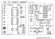
D D-STAR system descriptionArea 1Repeater 1Zone AArea 2Repeater 2Area 3(Gateway)Repeater 3Area 4Repeater 4Internet12Area 5Repeater 5Zone BArea 6(Gateway)Repeater 6Area 7Repeater 7Area 8Repeater 834Area:The Area is the communication rangethat is covered by a single repeater.The repeater is called an area, oraccess repeater in the D-STAR system.Link repeater:The microwave (10 GHz) link repeaterprovides linking with another repeatersite (Area) for zone construction.Zone:The Zone is composed of several areas, that are linkedby a 10 GHz microwave link.Areas 1 to 4 and 5 to 8 make up a zone in the exampleabove.Gateway repeater:Gateway repeaters provide communications betweendifferent zones via the internet.Repeater 3 and 6 are gateway repeaters at theexample above.56789101112131415161718192021iv
■ Electronic keyer functions................................ 50D Memory keyer menu construction............... 50D Memory keyer send menu........................... 51D Editing a memory keyer............................... 52D Contest number Set mode........................... 53D Keyer Set mode........................................... 54■ Operating RTTY (FSK).................................... 56■ RTTY functions................................................ 57D Construction of RTTY menu........................ 57D About RTTY reverse mode.......................... 58D Twin Peak Filter............................................ 58D RTTY decoder............................................. 59D RTTY Set mode........................................... 60■ Operating AM/FM............................................ 61■ Tone squelch operation.................................... 62■ DTCS operation............................................... 63■ Tone scan/DTCS code scan operation............ 64■ Repeater operation.......................................... 65D Repeater access tone frequency setting..... 65D One-touch repeater function........................ 66D Transmit frequency monitor check............... 66D 1750 Hz tone burst...................................... 66D Setting the Auto Repeater ranges(U.S.A. and Korea versions only)................. 67D Turning ON the Auto Repeater function(U.S.A. and Korea versions only)................. 68D Storing a non standard repeater ................. 685 FUNCTIONS FOR RECEIVE........................ 69–77■ AFC operation.................................................. 69■ RIT function..................................................... 69D RIT monitor function.................................... 69■ Simple band scope.......................................... 70■ Preamplifier...................................................... 71■ Attenuator........................................................ 71■ AGC function................................................... 72D AGC speed selection................................... 72D Setting the AGC time constant.................... 72■ IF filter selection............................................... 73D IF filter selection.......................................... 73D Filter passband width setting....................... 73D 1st IF filter selection..................................... 74D IF (DSP) filter shape.................................... 74■ Twin PBT operation.......................................... 75■ Noise Blanker.................................................. 76D NB Set mode............................................... 76■ Meter peak hold function................................. 76■ Noise Reduction.............................................. 77■ Dial Lock function............................................ 77■ Notch function.................................................. 776 FUNCTIONS FOR TRANSMIT...................... 78–84■ VOX function.................................................... 78D Using the VOX function................................ 78D Adjusting the VOX function.......................... 78■ Break-in function.............................................. 79D Semi Break-in operation.............................. 79D Full Break-in operation................................ 79■ Speech compressor......................................... 80■ Transmit filter width selection.............................80■ ∂TX function.................................................... 81D ∂TX Monitor function................................... 81■ Monitor function............................................... 81■ Split frequency operation................................. 82■ Quick Split function.......................................... 83D Split frequency offset setting....................... 83D Split Lock function....................................... 83■ Measuring SWR............................................... 84D Spot measurement...................................... 84D Plot measurement....................................... 847 DV MODE PROGRAMMING......................... 85–92■ Call sign programming..................................... 85D “MY” (Your own call sign) programming....... 85D “UR” (Destination call sign) programming.... 86D “R1” (Access/Area repeater call sign) and“R2” (Link/Gateway repeater call sign)programming................................................ 87■ Repeater list..................................................... 88D Repeater list contents.................................. 88■ Repeater list programming..................................89■ Editing a repeater list....................................... 91■ Clearing a repeater list........................................928 DV MODE OPERATION.............................. 93–120■ Digital mode operation..................................... 93■ Call sign setting............................................... 93■ Receiving a D-STAR repeater.......................... 94■ Received call signs.......................................... 95D Desired call record display.......................... 95D One-touch reply using the call record.......... 96■ Copying the call sign........................................ 97D Copying the call sign memory contents....... 97D Copying the call record contentsinto call sign memory................................... 98■ DR (D-STAR Repeater) mode operation......... 99D Communication Form.................................. 99D Access repeater scan................................ 100■ Calling CQ..................................................... 101D Storing the set data................................... 102123456789101112131415161718192021vi
TABLE OF CONTENTS■ Calling a specific station................................ 103D Confirming the setting............................... 105D Settings for “UR” and “R2,” depending on thecommunication form.................................. 105■ Simplex operation using the VFO.................. 106D Making a simplex CQ call or a call toan individual station................................... 106■ Repeater operation using the VFO................ 107D Making a CQ call or a call to an individualstation through your local area (access)repeater (Local Area call).......................... 107D Making a CQ call or a call to an individualstation through a link repeater in the samezone (Zone call)......................................... 108D Making a CQ call or a call to an individualstation through gateway repeaters(Gateway call)............................................ 109D Settings for “UR” and “R2,” depending on thecommunication form.................................. 110■ Message operation........................................ 111D TX message programming........................ 111D Message Transmission.............................. 112D RX message display.................................. 112■ DV automatic detection.................................. 113■ Automatic Reply function............................... 113■ Digital squelch functions................................ 114■ EMR communication...................................... 115D Adjusting the EMR AF level....................... 115■ BK mode communication............................... 116■ Low-speed data communication.................... 117D Connection................................................ 117D Low-speed data communication applicationsetting........................................................ 117D Low-speed data communication operation.117■ Packet loss indication.................................... 117■ DV Set mode description............................... 118D DV Set mode settings................................ 1189 GPS/GPS-A OPERATION........................ 121–137■ GPS operation............................................... 121D GPS screen construction........................... 121D GPS data communication.......................... 122D Sentence formatter setting........................ 122D Position display.......................................... 123D Saving your own or received position data. 124D Display the Grid Locator information......... 124D GPS automatic transmission..................... 124D GPS message programming..................... 125D Received GPS message display............... 126■ GPS memory operation................................. 127D Add a GPS memory.................................. 127D Edit a GPS memory................................... 129D GPS alarm setting..................................... 130D GPS memory clearing............................... 131■ GPS Set mode............................................... 132■ GPS-A operation............................................ 137D GPS-A function.......................................... 137D GPS-A code details................................... 13710 MEMORY OPERATION............................ 138–144■ General description........................................ 138D Memory channel contents......................... 138■ Memory channel selection............................. 139D Selection in the VFO mode........................ 139D Selection in the Memory mode.................. 139■ Call channel selection.................................... 139■ Memory channel programming...................... 140D Programming in the VFO mode................. 140D Programming in the Memory mode........... 140■ Call channel programming............................. 141■ Memory clearing............................................ 141■ Memory contents copying.............................. 142D Copying in the VFO mode......................... 142D Copying in the Memory mode.................... 142■ Memory name programming.......................... 143■ Memo pad function........................................ 144D Writing the displayed data into memo pads. 144D Calling up the memo pads......................... 14411 SCANS...................................................... 145–152■ Scan types..................................................... 145■ Preparation.................................................... 146■ Voice Squelch Control function...................... 146■ Scan set mode............................................... 147■ Scan edges programming.............................. 148■ Programmed scan/Fine programmed scan(VFO mode)................................................... 149D About the Fine programmed scan............. 149■ Memory scan (Memory mode)....................... 150D Memory scan............................................. 150D Mode Select scan...................................... 150D Setting/Cancelling Select Memory channels. 151D Select Memory scan.................................. 151■ ∂F scan and Fine ∂F scan............................ 152D About the Fine ∂F scan............................. 152vii
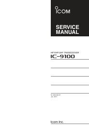
1PANEL DESCRIPTION■ Front panelq!2!1wertyui o !01q POWER SWITCH [POWER] (p. 31)➥ Push to turn ON the transceiver power.• First, confirm the DC power source is turned ON.➥ Hold down for 1 second to turn OFF the power.w TRANSMIT SWITCH [TRANSMIT] (p. 46)Push to select transmit or receive.• While transmitting, the MAIN Band’s TX/RX indicator(i) lights red. Only on the satellite mode, the SUBBand’s TX/RX indicator (!6) lights red.• While receiving or when the squelch opens, the indicatorlights green.e ANTENNA TUNER SWITCH [TUNER] (p. 159)(Frequency band: HF/50 MHz)➥ Push to turn the internal antenna tuner ON orOFF (bypass).• “ ” appears when the tuner is turned ON.• The internal antenna tuner settings can be memorizedin each frequency band.➥ Hold down for 1 second to manually start the antennatuner.• If the tuner cannot tune the antenna within 20 seconds,the tuning circuit is automatically bypassed.r ANTENNA•METER SWITCH [ANT•METER]ANTENNA SWITCH Operation (p. 158)(Frequency band: HF/50 MHz)➥ Push to select either the ANT1 or ANT2 connector.METER SWITCH Operation (p. 45)(Frequency band: ALL)➥ Hold down for 1 second to toggle the transmitmeter function between ALC, COMP and SWR.t HEADPHONE JACK [PHONES]Plug in standard stereo headphones (impedance: 8to 16 ø).• Output power: More than 5 mW with an 8 ø load.• When headphones are connected, the internal speaker,and any external speaker, are disabled.• The MAIN and SUB Band audio can be mixed or separatedwhen using stereo headphones, depending on the“Phone Separate” option in the Set mode. (p. 166)y ELECTRONIC KEYER JACK [ELEC-KEY]Plug in a bug or paddle type key to use the internalelectronic keyer for CW operation. (p. 22)• Set the keyer type to ELEC-KEY, BUG KEY or Straightkey in the “Keyer Type” item of the Keyer Set mode.• When a straight key is connected, “Straight key” mustbe selected in the “Keyer Type” item of the Keyer Setmode. (p. 55)• A straight key jack is located on the rear panel. See[KEY] on pages 11 and 22.• You can reverse the keyer paddle polarity (dot anddash) in the “Paddle Polarity” item of the Keyer Set mode.(p. 55)• Four keyer memory channels are available for your convenience.(p. 51)(dot)(com)(dash)u MICROPHONE CONNECTOR [MIC]Plug in the supplied or an optional microphone.• See page 199 for appropriate microphones.• See page 30 for microphone connector information.i MAIN BAND TX/RX INDICATOR➥ Lights green when the squelch opens, or a signalis received on the MAIN Band; lights red duringtransmit.➥ Blinks green when an off-frequency signal is received,depending on the “FM/DV Center Error”option in the Set mode. (p. 162)
PANEL DESCRIPTION1o MAIN BAND RF GAIN CONTROL/SQUELCH CONTROL [RF/SQL](outer control; p. 44)Rotate to adjust the RF gain and squelch thresholdlevel for the MAIN Band.The squelch removes noise output to the speakerwhen no signal is received. (closed condition)!0 MAIN BAND AF CONTROL [AF](inner control; p. 45)Rotate to adjust audio output level to the speaker orheadphones on the MAIN Band.IncreasesDecreases• The squelch is particularly effective for AM and FM, butalso works in other modes.• The 12 to 1 o’clock position is recommended for themost effective use of the [RF/SQL] control.• [RF/SQL] operates as only an RF gain control in SSB,CW and RTTY (Squelch is fixed open), or a squelchcontrol in AM, FM and DV (RF gain is fixed at maximumsensitivity), when “Auto” is selected as the “RF/SQL Control” item option in the Set mode. (p. 162)• When used as an RF gain/squelch controlNoise squelch (FM/DV modes)Squelch isRecommended levelopen.MaximumRF gainRF gainadjustablerangeS-metersquelch• When used as an RF gain control(Squelch is fixed open; SSB, CW and RTTY only)AdjustablerangeMinimum RF gainMaximumRF gainWhile rotating the RF gain control, a faint noise maybe heard. This comes from the DSP unit and doesnot indicate an equipment malfunction.• When used as a squelch control(RF gain is fixed at maximum.)Noise squelchthreshold(FM mode)Squelch isopen.Noise squelch (FM/DV modes)ShallowDeepS-meter squelchthresholdS-metersquelch!1 NOTCH SWITCH [NOTCH] (p. 77)(Mode = Auto notch : SSB/AM/FMManual notch : SSB/CW/RTTY/AM)➥ In the SSB and AM modes, push to toggle thenotch function between auto, manual and OFF.• Either the Auto or Manual notch function can beturned OFF in the “[NOTCH] SW” item of the Setmode. (p. 36)➥ In the FM mode, push to turn the Auto Notchfunction ON or OFF.➥ In the CW or RTTY mode, push to turn the ManualNotch function ON or OFF.• “MNF” appears when the Manual Notch function isON.• “ANF” appears when the Auto Notch function is ON.• No indicator appears when the notch filter is OFF.➥ Hold down for 1 second to switch the manualfilter characteristics from wide, mid and narrow,when the Manual Notch function is selected.✔ What is the notch filter?The notch filter is a narrow filter that eliminates unwantedCW or AM carrier tones, while preservingthe desired voice signal. The DSP circuit automaticallyadjusts the notch frequency to effectively eliminateunwanted tones.!2 <strong>MANUAL</strong> NOTCH FILTER CONTROL [NOTCH](outer control; p. 77)Rotate to adjust the notch frequency to reject aninterfering signal while the manual function is ON.• Notch filter center frequency:SSB/RTTY : –1040 Hz to +4040 HzCW: CW pitch freq. –2540 Hz toCW pitch freq. +2540 HzAM: –5060 Hz to +5100 HzLower frequencyHigher frequencyThe optional UX-9100 is required for 1200 MHz frequencyband operation.The optional UT-121 is required for DV mode operation.2123456789101112131415161718192021
1 PANEL DESCRIPTION■ Front panel (continued)!5!4!38!6 !7 !8!9 @0 @1 @2 @3 @4 @5 @6 @7 @8!3 MENU SWITCH [MENU] (p. 19)➥ Push to change the set of functions assigned toswitches ([F-1] to [F-5]).• Toggles the function display menu between M1(Menu 1), M2 (Menu 2), M3 (Menu 3), D1 and D2.➥ Hold down for 1 second to enter the Set mode.Push to return to the previous screen display.!4 NOISE REDUCTION LEVEL CONTROL [NR](inner control; p. 77)Rotate to adjust the DSP noise reduction levelwhen the noise reduction function is in use. Set formaximum readability.• To use this control, first push [NR] (!5).!8 SUB BAND AF CONTROL [AF] (inner control; p. 45)Rotate to adjust audio output level to the speaker orheadphones on the SUB Band.!9 MIC GAIN CONTROL [MIC GAIN] (p. 46)Rotate to adjust the microphone gain.• The transmit audio tone in the SSB, AM and FM modes canbe independently adjusted in the tone control Set mode.(p. 169)✔ How to set the microphone gain.Set the meter function to ALC. (p. 45) While speakingat normal voice level, adjust the [MIC GAIN]control so that in the SSB or AM modes, the ALCmeter swings within the ALC range.IncreasesRecommended level forIcom microphonesDecreasesIncreases3Decreases!5 NOISE REDUCTION SWITCH [NR] (p. 77)Push to turn DSP noise reduction ON or OFF.• “NR” appears when noise reduction is ON.!6 SUB BAND TX/RX INDICATORLights green when the squelch opens, or a signal isreceived on the SUB Band; lights red during transmitin the satellite mode.➥ Blinks green when an off-frequency signal is received,depending on the “FM/DV Center Error”option in the Set mode. (p. 162)!7 SUB BAND RF GAIN CONTROL/SQUELCH CONTROL [RF/SQL](outer control; p. 44)Rotate to adjust the RF gain and squelch thresholdlevel on the SUB Band.The squelch stops noise output to the speakerwhen no signal is received. (closed condition)See o on page 2 for details.@0 RF POWER CONTROL [RF POWER] (p. 46)Rotate to continuously vary the RF output power.DecreasesFrequency bandIncreasesRF output power rangeHF/50 MHz 2 to 100 W (AM: 2 to 30 W)144 MHz 2 to 100 W430 MHz 2 to 75 W1200 MHz 1 to 10 W@1 CW PITCH CONTROL [CW PITCH](outer control; p. 49)(Mode: CW)Rotate to shift the received CW audio pitch and theCW sidetone pitch without changing the operatingfrequency.• The pitch can be adjusted from 300 to 900 Hz in approximately5 Hz steps.Lower pitchHigher pitch
PANEL DESCRIPTION1@2 ELECTRONIC CW KEYER SPEED CONTROL[KEY SPEED] (p. 49)(Mode: CW)Rotate to adjust the keying speed of the internalelectronic CW keyer to between 6 wpm (minimum)and 48 wpm (maximum).SlowFast@3 PREAMP•ATTENUATOR SWITCH [P.AMP•ATT]PREAMP SWITCH Operation (p. 71)(Frequency band: HF/50 MHz)➥ Push to select one of two receive RF preamplifiers,or to bypass them.• “P. AMP ” is a wide dynamic range preamplifier. It ismost effective for the 1.8 to 21 MHz bands.• “P. AMP ” is a high-gain preamplifier. It is most effectivefor the 24 to 50 MHz bands.• No indicator appears when the preamplifiers are notselected.(Frequency band: 144/430/1200 MHz)➥ Push to turn an AG-25, AG-35 or AG-1200 preamplifierunit* ON or OFF, if installed.• “P.AMP” appears when the preamplifier unit is ON.*These preamplifier units have been discontinued, butthey can still be used.✔ What is the preamplifier?The preamplifier amplifies signals in the front end toimprove the S/N ratio and sensitivity. Select “P. AMP” or “P. AMP ” when receiving weak signals.ATTENUATOR SWITCH Operation (p. 71)➥ Hold down for 1 second to turn ON the attenuator.• “ATT” appears when the attenuator is ON.➥ Push to turn OFF the attenuator.• “ATT” disappears.✔ What is the attenuator?The attenuator prevents a desired signal from beingdistorted when very strong signals are near it, orwhen very strong electromagnetic fields, such asfrom a broadcasting station, are near your location.@4 NOISE BLANKER SWITCH [NB] (p. 76)➥ Push to turn the noise blanker ON or OFF. Thenoise blanker reduces pulse-type noise such asthat generated by vehicle ignition systems. Thenoise blanker is not effective for non-pulse-typenoise.• “NB” appears when the noise blanker is ON.➥ Hold down for 1 second to display the “NB”screen. Push to return to the previous screendisplay.@5 VOX/BK-IN SWITCH [VOX/BK-IN]VOX SWITCH Operation (p. 78)(Mode: SSB/AM/FM/DV)➥ Push to turn the VOX function ON or OFF.➥ Hold down for 1 second to display the “VOX”screen. Push to return to the previous screendisplay.✔ What is the VOX function?The VOX function (voice operated transmission)automatically starts transmission when you speakinto the microphone; then automatically returns toreceive when you stop speaking.BK-IN SWITCH Operation (p. 79)(Mode: CW)➥ Push to toggle the break-in operation betweensemi break-in and full break-in, or to turn OFFthe break-in function.➥ Hold down for 1 second to display the “BKIN”screen (Break-in). Push to return to the previousscreen display.✔ What is the break-in function?The break-in function automatically switches betweentransmit and receive with your CW keying.Using Full break-in function (QSK), you can hearthe receive frequency in-between keying.@6 MONITOR SWITCH [MONITOR] (p. 81)➥ Push to turn the Monitor function ON or OFF tolisten to your own transmitted audio.• “MONI” appears when this function is ON.• In CW mode, the CW sidetone can be heard, regardlessof the [MONITOR] switch setting.➥ Hold down for 1 second to display the “MONI”screen (Monitor) to set the monitor level. Push toreturn to the previous screen display.@7 CALL•GPS SWITCH [CALL•GPS]CALL SWITCH Operation (p. 139)Push to select the call channel.GPS SWITCH Operation (p. 121)Hold down for 1 second to display the “GPS” screen.Push to return to the previous screen display.@8 FUNCTION SWITCHES [F1]–[F5]Push to select the function which is indicated on theLCD display above each switch. (p. 19)• The functions vary, depending on the selected menuand the operating mode.The optional UX-9100 is required for 1200 MHz frequencyband operation.4123456789101112131415161718192021
1 PANEL DESCRIPTION■ Front panel (continued)#1 #2#3#4#5 #6 #7@9 #05@9 MODE SWITCHESPush to select your desired operating mode. (p. 43)• The built-in speech synthesizer announces the selectedmode when the “SPEECH [MODE] SW” item is set to“ON” in the Set mode. (p. 164)[SSB] (p. 47)➥ Push to alternately select the USB or LSB modes.• “USB” or “LSB” appears.➥ In the SSB mode, hold down for 1 second to selectthe SSB data mode (USB-D, LSB-D).• “D” appears in addition to “USB” or “LSB.”➥ In the SSB data mode, push to return to the normalSSB mode.[CW/RTTY] (pp. 48, 56)➥ Push to alternately select the CW or RTTYmodes.• “CW” or “RTTY” appears.➥ Hold down for 1 second to switch between theCW and CW-R (CW reverse) modes, in the CWmode.• “CW-R” appears when the CW reverse mode isselected.➥ Hold down for 1 second to switch between theRTTY and RTTY-R (RTTY reverse) modes inthe RTTY mode.• “RTTY-R” appears when the RTTY reverse mode isselected.[AM/FM] (p. 61)➥ Push to alternately select the AM or FM modes.• “AM” or “FM” appears.➥ Hold down for 1 second to select the AM or FMdata mode (AM-D/FM-D).• “D” appears in addition to “AM” or “FM.”➥ In the data mode, push to return to the normalAM or FM mode.NOTE:• In the AM mode, you can transmit on only theHF/50MHz frequency bands.• The AM mode cannot be selected on the 1200MHz frequency band.[DV•DR] (p. 85)➥ Push to select the DV mode.• “DV” appears.➥ Hold down for 1 second to select the DR mode.• “ ” appears.➥ In the DR mode, push to cancel it.• “ ” disappears.#0 FILTER SWITCH [FILTER] (p. 73)➥ Push to select one of three IF filter settings ( / /).• The selected filter passband width and shifting valueare displayed for 2 seconds on the LCD display.➥ Hold down for 1 second to display the “FIL”screen (Filter) to set the filter passband width.➥ When the “FIL” screen is displayed, hold down for1 second to return to the previous screen display.#1 TRANSMIT FREQUENCY CHECK SWITCH [XFC]➥ During split frequency or repeater operation, holddown to listen to the transmit frequency. (p. 82)• While holding down this switch, the transmit frequencycan be changed with the main dial, keypador memo pad.• When the split lock function is turned ON, push[XFC] to cancel the dial lock function. (pp. 82, 162)➥ When the RIT function is turned ON, holddown to listen to the receive frequency. (RIT istemporarily cancelled.) (p. 69)➥ When the ∂TX function is turned ON, hold downto listen to the transmit frequency (including ∂TXfrequency offset). (p. 81)➥ In the simplex operation, hold down to listen tothe receive frequency.• The squelch is closed and the interference rejectfunction is temporary OFF while holding down thisswitch.➥ In the DV mode, the RX monitoring mode is selectedby holding down this switch. (p. 118)
1 PANEL DESCRIPTION■ Front panel (continued)#8 #9$0 $1$2 $3$4$5$6$7$8$9%0#8 VFO/MEMORY SWITCH [VFO/MEMO]➥ Push to switch between the VFO and memorymodes. (pp. 34, 139)➥ Hold down for 1 second to copy the memory contentsto the displayed VFO on the MAIN Band.(p. 142)#9 MEMO PAD-WRITE SWITCH [MP-W] (p. 144)Push to write the displayed data into a memo pad.• The 5 most recent entries remain in the memo pads.• The memo pad capacity can be extended from 5 to10 in the “Memopad Numbers” item of the Set mode.(p. 164)$0 MEMORY WRITE SWITCH [MW] (p. 140)Hold down for 1 second to store VFO data into theselected memory channel.• This can be done in both the VFO and memory modes.$1 MEMO PAD-READ SWITCH [MP-R] (p. 144)Push to sequentially call up the contents from thememo pads.The 5 (or 10) most recently programmed frequenciesand operating modes can be recalled, startingfrom the most recent.• The memo pad capacity can be increased from 5 to10 in the “Memopad Numbers” item of the Set mode.(p. 164)$2 MEMORY CLEAR SWITCH [M-CLR] (p. 141)In the Memory mode, hold down for 1 second toclear the memory channel.• The channel becomes a blank channel.• This switch is disabled in the VFO mode.$3 TUNING STEP•REPEATER GROUP SWITCH[TS•GRP]TUNING STEP SWITCH Operation (p. 38)➥ Push to toggle between the kHz and MHz* quicktuning step, or turn OFF the quick tuning.* When the HF/50 MHz frequency band is selected,MHz step cannot be selected.• When the “Z” quick tuning icon is displayed abovethe kHz or MHz digit, the frequency is changed inprogrammed quick tuning steps or 1 MHz steps.• When the quick tuning is OFF, the frequency ischanged in 10 Hz steps.➥ When the quick tuning is ON, hold down for1 second to display the “TS” screen (Tuning Step)to select the quick tuning step. (p. 38)• 0.1, 1, 5, 6.25, 9, 10, 12.5, 20, 25, 50 and 100 kHzsteps are independently selectable for each operatingmode.➥ When the quick tuning is OFF, hold down for1 second to turn the minimum tuning step of1 Hz ON or OFF. (p. 39)CALL SIGN GROUP SWITCH Operation (p. 93)(Mode: DV) (Only when “ ” is displayed.)➥ Push to switch the call sign group.➥ Hold down for 1 second to enter the repeater callsign group selection mode.• “≈” blinks.➥ When in the repeater group selection mode,push to cancel it.7
PANEL DESCRIPTION1$4 PBT CLEAR SWITCH [PBT-CLR] (p. 75)(Mode: SSB/CW/RTTY/AM)➥ Push to display the filter passband width andshifting value for 1 second on the function display.➥ Hold down for 1 second to reset the PBT settings.$5 PASSBAND TUNING CONTROLS [TWIN-PBT](p. 75)(Mode: SSB/CW/RTTY/AM)Adjusts the receiver’s IF filter passband widthusing the DSP circuit.• Rotate this control or push [PBT-CLR] to display thePBT settings (passband width and shifting value) for 1second on the function display.• Hold down [PBT-CLR] for 1 second to clear the PBTsettings.• The PBT is adjustable in 50 Hz steps in the SSB/CW/RTTY modes, and 200 Hz in the AM mode. In this time,the shift value changes in 25 Hz steps in the SSB/CW/RTTY modes, and 100 Hz in the AM mode.• These controls function as an IF shift control.✔ What is the PBT control?The PBT function electronically modifies the IF passbandwidth to reject interference. This transceiver uses the DSPcircuit for the PBT function.PBT2PBT1– +High cutCenterLow cut$6 SUB DIAL SWITCH [SUB DIAL] (p. 33)Push to turn the SUB Dial function ON or OFF.• “ ” appears when the SUB Dial function is ON.$7 SUB DIAL CONTROL(outer control; p. 33)Rotate to change the SUB Band frequency.DecreasesIncreasesThe [SUB DIAL] control’s tuning Band (MAIN orSUB) and frequency steps differ, depending onthe combination of the SUB Dial function andSUB Band setting mode status, and the status ofthe quick tuning function. See page 33 for details.$8 MEMORY CHANNEL CONTROL [M-CH](inner control; p. 139)Select a memory channel.• Rotate clockwise to select a higher memory channelnumber; rotate counterclockwise to select a lower memorychannel number.Lower channelHigher channel$9 RIT SWITCH [RIT] (p. 69)➥ Push to turn the RIT function ON or OFF.• Use [RIT/∂TX] control to vary the RIT frequency.➥ Hold down for 1 second to add the shift frequencyof the RIT function to or subtract it from the displayedfrequency.✔ What is the RIT function?The RIT (Receiver Incremental Tuning) shifts the receivefrequency without shifting the transmit frequency.This is useful for fine tuning stations calling you off-frequencyor when you prefer to listen to slightly differentsoundingvoice characteristics, etc.%0 ∂TX SWITCH [∂TX] (p. 81)➥ Push to turn the ∂TX function ON or OFF.• Use [RIT/∂TX] control to vary the ∂TX frequency.➥ Hold down for 1 second to add the shift frequencyof the ∂TX function to or subtract it fromthe displayed frequency.✔ What is the ∂TX function?∂TX shifts the transmit frequency without shifting the receivefrequency. This is useful for simple split frequencyoperation in CW, etc.123456789101112131415161718192021The optional UT-121 is required for DV mode operation.8
1 PANEL DESCRIPTION■ Front panel (continued)%1%2%3%4%1 MAIN DIAL (pp. 37, 161)Rotate to change the displayed frequency, selectthe Set mode settings, etc.When the SUB Band setting mode is ON, rotating[MAIN DIAL] changes the SUB Band frequency.(p. 33)%2 CLEAR SWITCH [CLEAR] (pp. 69, 81)Hold down for 1 second* to clear the RIT/∂TX shiftfrequency.* When the “Quick RIT Clear” item in the Set mode isON, push momentarily to reset the shift frequency.(p. 164)%3 RIT/∂TX CONTROL [RIT/∂TX] (pp. 69, 81)When either or both the RIT/∂TX functions are ON,rotate to adjust the RIT/∂TX frequency shift.• Rotate the control clockwise to increase the frequency,or counterclockwise to decrease the frequency.• The frequency shift range is ±9.99 kHz in 10 Hz steps.The control tunes in 1 Hz steps when the operating frequencyreadout is set to the 1 Hz step readout. However,the 1 Hz digit is not displayed on the frequencyshift readout.Shift high%4 SPEECH/LOCK SWITCH [SPEECH/LOCK]SPEECH SWITCH Operation (p. 45)➥ Push to audibly announce the S-meter level, thedisplayed frequency and the operating mode.• The S-Level announcement can be turned OFFin the “SPEECH S-Level” item of the Set mode.(p. 164)• When RIT and/or ∂TX are ON, the RIT/∂TX offset isnot included in the frequency announcement.LOCK SWITCH Operation (p. 77)➥ Hold down for 1 second to turn the Dial Lockfunction ON or OFF.• The function electronically locks the Main dial.• “ ” appears when the function is ON.NOTE: The [SPEECH/LOCK] switch operation toactivate the voice synthesizer or the dial lockfunctions can be replaced in the “[SPEECH/LOCK] SW” item of the Set mode. (p. 164)Shift low9
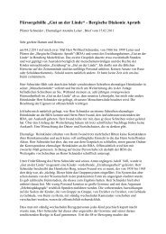
PANEL DESCRIPTION1■ Rear paneli u yq ANTENNA CONNECTOR 1 [ANT1]w ANTENNA CONNECTOR 2 [ANT2](pp. 24, 25, 158)Connect a 50 ø antenna with a PL-259 plug connectorfor the HF/50 MHz frequency band.When using an optional AH-4 hf/50 mhz automat i c antenna tuner, connect it to the [ANT1]connector. Connecting the AH-4 switches the internalantenna tuner from [ANT1] to [ANT2].e 1200 MHz BAND ANTENNA CONNECTOR[1200MHz ANT] (pp. 24, 158)Connect a 1200 MHz 50 ø antenna with a type-Nconnector, when the optional UX-9100, 1200 MHzband unit, is installed.r MAIN BAND EXTERNAL SPEAKER JACK[EXT-SP (MAIN)]t SUB BAND EXTERNAL SPEAKER JACK[EXT-SP (SUB)] (p. 25)Connect to an external speaker (4 to 8 ø).By connecting an external speaker to each or bothjacks, the audio output for both the MAIN and SUBBands can be configured as shown below.External speakerconnectionNo connectionMAIN AFTo the MAIN jack External speakerInternal speakerSUB AFInternal speakerTo the SUB jack Internal speaker External speakerBothqwExternal speakersery 430 MHz ANTENNA CONNECTOR [430MHz ANT](pp. 24, 25, 158)Connect a 50 ø antenna with a type-N connectorfor the 430 MHz frequency band.u 144 MHz ANTENNA CONNECTOR [144MHz ANT](pp. 24, 25, 158)Connect a 50 ø antenna with a PL-259 connectorfor the 144 MHz frequency band.i DC POWER SOCKET [DC 13.8V] (p. 27)Connect 13.8 V DC through the supplied DC powercable.tRear panel view12345678910111213141516171819202110
1 PANEL DESCRIPTION■ Rear panel (Continued)o!0!1!2!3!4!5!6 !7!8o GROUND TERMINAL [GND] (p. 22)Connect this terminal to a ground to prevent electricalshocks, TVI, BCI and other problems.!0 TUNER CONTROL SOCKET [TUNER] (p. 29)Connect the control cable from an optional AH-4 hf/50 mh z au to m at i c antenna tuner.!1 DATA1 JACK [DATA1] (pp. 26, 168)➥ Connect a PC through the optional OPC-1529Rdata communication cable, for low-speed datacommunication in the DV mode. (p. 117)➥ Connect a GPS receiver through the optionalOPC-1529R data communication cable, forGPS operation. (p. 121)!2 DATA2 SOCKET [DATA2] (pp. 26, 171)Connect a TNC (Terminal Node Controller), etc. forhigh speed data communications.!3 STRAIGHT KEY JACK [KEY] (p. 24)Connect a straight key or external electronic keyeroutput using a standard 1 ⁄4 inch plug.• To use the internal electronic keyer for CW operation,connect to [ELEC-KEY] on the front panel. (p. 1)(+)(_)!4 ALC INPUT JACK [ALC] (p. 25)Connect to the ALC output jack of a non-Icom linearamplifier.!5 SEND CONTROL JACK [SEND] (p. 25)When transmitting, goes to ground to control an externalunit, such as a non-Icom linear amplifier.!6 ACCESSORY SOCKET [ACC]Connect control lines for external equipment suchas a linear amplifier, an automatic antenna selector/tuner, a TNC for data communications, etc.• See page 13 for socket information.!7 CI-V REMOTE CONTROL JACK [REMOTE](pp. 26, 183)➥ Connect a PC, using the optional CT-17 ci-v levelconverter, for external control of the transceiver.➥ Use for transceive function with another IcomCI-V transceiver or receiver.When the transceive function is set to ON,changing the frequency, operating mode, etc.on the IC-9100 automatically changes thosesettings on other Icom transceivers or receivers,and vice versa. (p. 167)➥ Connect another IC-9100, using a mini plugcable*, for transceiver to transceiver cloning.* Purchase separately11
PANEL DESCRIPTION1!8 USB (Universal Serial Bus) PORT [USB]Using a USB cable, connect a PC to do the following:- Input modulation (p. 167)- Remotely control the transceiver using CI-V commands(p. 183)- Send the received audio to the PC- Send the decoded characters to the PC(pp. 59, 167)- Low-speed data communication in the DV mode(p. 167)- Cloning using the optional CS-9100 cloning softwar e (p. 182)• Two COM port numbers are assigned to the [USB] connector.One of them is “USB1,” used for cloning andCI-V operation. The other one is “USB2,” whose functionis selected in “USB2/DATA1 Func” (63) item of the Setmode. (p. 167)About the USB driver:The USB driver and the installation guide can bedownloaded from our website.➥ http://www.icom.co.jp/world/index.htmlThe following items are required:PC• Microsoft ® Windows ® XP,Microsoft ® Windows Vista ® orMicrosoft ® Windows ® 7 OS• A USB 1.1 or 2.0 portOther items• USB cable (purchase separately)• PC software (such as optional RS-BA1 or CS-9100)NEVER connect the transceiver to a PC until theUSB driver installation has been completed.About the modulation input:Select “USB” in the Set mode item “DATA OFFMOD” or “DATA MOD.” The modulation input levelfrom the USB jack can be set in the Set mode item“USB MOD Level.” (p. 167)12345678910111213141516171819202112
1 PANEL DESCRIPTION■ Rear panel (Continued)D ACC socket information• ACC socketACC PIN No. NAME DESCRIPTION SPECIFICATIONS139 10 11 125 6 7 81 2 3 4Rear panel viewq brown i grayw red o whitee orange !0 blackr yellow !1 pinkt green !2 lighty blue blueu purple !3 lightgreenColor refers tothe cable strandsof the suppliedcable.1 8 V Regulated 8 V output.Output voltageOutput current2 GND Connects to ground. ———3HSEND* 1, 2 Input/outputpin.An external equipmentcontrols the transceiver.When this pin goes low,the transceiver transmits.The transceiver outputs alow signal to control externalequipment.Input voltage (High)Input voltage (Low)Current flowOutput voltage (Low)Current flow: 8 V ± 0.3 V: Less than 10 mA: 2.0 V to 20.0 V: –0.5 V to +0.8 V: Max. 20 mA: Less than 0.1 V: Max. 200 mA4 NC ——— ———5 BAND Band voltage output. Output voltage : 0 to 8 V6 ALC ALC voltage input.7VSEND* 1, 2 Input/outputpin.An external equipmentcontrols the transceiver.When this pin goes low,the transceiver transmits.The transceiver outputs alow signal to control externalequipment.Control voltageInput impedanceInput voltage (High)Input voltage (Low)Current flowOutput voltage (Low)Current flow: –3 V to 0 V: More than 3.3 k˘: 2.0 V to 20.0 V: –0.5 V to +0.8 V: Max. 20 mA: Less than 0.1 V: Max. 200 mA8 13.8 V 13.8 V output when power is ON. Output current : Less than 1 A9 NC ——— ———10 FSKK Controls RTTY keying11 MOD Modulator input.12 AF* 3 Fixed level, regardless of the [AF]AF detector output.control position.13 SQL S* 3 Squelch output.Grounded when squelch opens.“High” level“Low” levelOutput currentInput impedanceInput levelOutput impedanceOutput levelSQL openSQL closed: More than 2.4 V: Less than 0.6 V: Less than 2 mA: 10 k˘: Approx. 100 mV rms: 4.7 k˘: 100 to 300 mV rms: Less than 0.3 V/5 mA: More than 6.0 V/100 µA* 1 When the SEND terminal controls the inductive load (such as a relay), a counter-electromotive force can causethe transceiver’s malfunction or damage. To prevent this, we recommend adding a switching diode, such as an“1SS133,” on the load side of the circuit to the counter-electromotive force absorption.When the diode is added, a switching delay of the relay may occur. Be sure to check its switching action beforeoperation.[Example]ACC socketeHSEND oruVSENDi13.8 VSwitching diodeRelayTo a non-Icomlinear amplifier13* 2 VSEND is used for the 144 MHz, 430 MHz, and 1200 MHz bands, and HSEND is used for the HF/50 MHz bandsby default. You can change this setting in “VSEND Select” of the Set mode. (p. 166)* 3 The pin 12 (AF) and pin 13 (SQLS) output capabilities are for the MAIN Band’s AF and squelch by default. Youcan change this setting in “ACC AF/SQL Select” of the Set mode. (p. 166)
PANEL DESCRIPTION1• When connecting the ACC conversion cable (OPC-599)!3o!0!1!2tyuiqwerConnect to ACC socket ACC 1 24 5ACC 21836 71462573D DATA2 socket informationeDATA2 PIN No. NAME DESCRIPTION SPECIFICATIONStqwyrRear panel view1 DATA IN2 GND3 PTTP4 DATA OUT*5 AF OUT*6 SQL*q FSKKw GNDe HSENDr MODt AFy SQLSu 13.8 Vi ALCInput terminal for data transmit.(1200 bps: AFSK/9600 bps: G3RUH, GMSK)Common ground for DATA IN, DATAOUT and AF OUT.PTT terminal for packet operation.Connect to ground to activate thetransmitter.Data out terminal for 9600 bps operationonly.Data out terminal for 1200 bps operationonly.Squelch out terminal. This pin isgrounded when the transceiver receivesa signal which opens thesquelch.• To avoid interfering transmissions,connect squelch to the TNC to inhibittransmission when squelch is open.• Keep RF gain at a normal level, otherwisea “SQL” signal will not be output.q 8 Vw GNDe HSENDr BANDInput level (1200 bps)Input level (9600 bps)Input voltage (High)Input voltage (Low)Output impedanceOutput levelOutput impedanceOutput levelSQL openSQL closedt ALCy VSENDu 13.8 V———: 100 mV: 0.2 to 0.5 Vp-p: 2.0 V to 20.0 V: –0.5 V to +0.8 V: 10 k˘: 1.0 Vp-p: 4.7 k˘: 100–300 mV rms: Less than 0.3 V/5 mA: More than 6.0 V/100 µA* The pin 4 (DATA), pin 5 (AF) and pin 6 (SQL) output capabilities are for the MAIN Band’s AF and squelch by default.You can change this setting in “DATA AF/SQL Select” of the Set mode. (p. 166)12345678910111213141516171819202114
1 PANEL DESCRIPTION■ LCD display!0!2qwerqw!1oiuy!0oiuytq FREQUENCY READOUTSDisplays the operating frequency.• When the quick tuning icon “Z” is displayed, the frequencychanges in pre-set kHz or 1 MHz quick tuningsteps. (p. 38)• When the quick tuning icon “Z” is not displayed, the frequencychanges in 10 Hz or 1 Hz steps. (pp. 37, 39)w MULTI-FUNCTION METER INDICATION➥ Displays the signal strength while receiving.➥ Displays the relative output power, SWR, ALC orcompression levels while transmitting.➥ When the Meter Peak Hold function is ON, thepeak level of a received signal strength or theoutput power is displayed for approximately 0.5seconds.e ANTENNA ICON (p. 158)Displays which antenna connector is selected forHF/50 MHz.• “ANT1” appears when the [ANT1] connector is selected.• “ANT2” appears when the [ANT2] connector is selected.r ANTENNA TUNER ICONS (pp. 159, 160)➥ “ ” appears when the antenna tuner isturned ON; “ ” blinks during tuning.➥ “ ” appears when the optional AH-4 externalantenna tuner is connected to the [ANT1] connector,and [ANT1] is selected.y MEMORY CHANNEL READOUTSDisplays the selected memory channel.u SELECT MEMORY CHANNEL ICON➥ Appears when the selected memory channel isset as a select memory channel. (p. 151)➥ Appears when the repeater can be selected asthe access repeater in the DR mode. (p. 100)i DR MODE ICON (p. 43)Appears when the DR mode is selected.o RIT/∂TX ICONS (pp. 69, 81)➥ “RIT” appears when the RIT function is turnedON.➥ “∂TX” appears when the ∂TX function is turnedON.➥ Shows the shift frequency of the RIT or ∂TXfunction.!0 VOICE SQUELCH CONTROL ICON (p. 146)Appears when the VSC (Voice Squelch Control)function is turned ON.!1 DUPLEX ICON (p. 65)“DUP+” appears when plus duplex, “DUP –” appearswhen minus duplex (repeater) operation isselected.!2 DIAL LOCK ICON (p. 77)Appears when the Dial Lock function is turned ON.15t FUNCTION DISPLAY (p. 19)Shows the function of the function switches ([F1]–[F5]), Set mode items and IF passband width.
PANEL DESCRIPTION1!5 !4!3!6!7!8!9@0!3 TONE SQUELCH ICONS(Mode: FM)➥ “T” appears when the repeater tone function isON. (p. 65)➥ “TSQL” appears when the tone squelch functionis ON. (p. 62)➥ “DTCS” appears when the DTCS code squelchfunction is ON. (p. 63)(Mode: DV)➥ “DSQL” appears when the digital call sign squelchfunction is ON. (p. 114)➥ “CSQL” appears when digital code squelch functionis ON. (p. 114)!4 PACKET LOSS ICON(Mode: DV)Appears when the Packet Loss occurs.• While operating voice communication or low-speed datacommunication via the internet network, some packetsmay be lost due to network error (poor data throughputperformance). (p. 117)!5 MODE ICONS (p. 43)Displays the selected operating mode.• “D” appears when SSB data, AM data or FM data modeis selected.!6 BK MODE ICON (p. 116)(Mode: DV)➥ Appears when the BK (Break-in) function isturned ON.• The BK function allows you to break into a conversation,where the two original stations are communicatingwith call sign squelch enabled.➥ Blinks when receiving a break-in call.!5!4 !3!7 EMR MODE ICON (p. 115)➥ Appears when the EMR (Enhanced Monitor Receive)communication mode is selected.• In the EMR communication mode, no call sign settingis necessary when operating in the DV mode.➥ Blinks when receiving an EMR signal.!8 VOX ICON (p. 78)Appears when the VOX function is activated.!9 SPEECH COMPRESSOR ICON (p. 80)Appears when the Speech Compressor function isturned ON.@0 SATELLITE ICON (p. 153)Appears while the satellite mode is selected.: Normal satellite mode is selected.• When [MAIN DIAL] is rotated, both downlinkand uplink frequencies simultaneouslyincrease or decrease in the same step.: Reverse satellite mode is selected.• When [MAIN DIAL] is rotated clockwise,downlink frequency increase, and uplinkfrequency decrease in the same step.• When [MAIN DIAL] is rotated counterclockwise,downlink frequency decrease, and uplinkfrequency increase in the same step.The optional UT-121 is required for DV mode operation.12345678910111213141516171819202116
1 PANEL DESCRIPTION■ LCD display (Continued)@7@6 @5@4@3@2 @1@8@9#0#1 @4 @3 @2@1 SPLIT ICON (p. 82)Appears when the Split function is turned ON.@2 DSP FILTER ICON (p. 73)Displays the selected IF filter.@3 AGC ICONS (p. 72)Displays the selected AGC time constant.• “ ” for AGC fast; “ ” for AGC middle; “ ” for AGC slow;“-OFF” for AGC OFF.• In the FM and DV mode, “ ” for AGC fast is fixed.@4 PREAMP ICON (p. 71)Appears when a preamplifier is turned ON.• In HF/50 MHz frequency band, either “P. AMP ” or“P. AMP ” is displayed when the preamp 1 or preamp 2is ON.@5 GPS DATA COMMUNICATION ICONAppears while the GPS data communication functionis selected in the “GPS Out” item of the Setmode. (p. 168).• A GPS data from the GPS receiver, which is connectedto the [DATA1] jack, is output to the [USB] port.@7 GPS ICON (p. 132)➥ Appears when a valid position data is receivedfrom a GPS receiver that is connected to the[DATA1] jack.➥ Blinks when an invalid data is received from theGPS receiver.@8 GPS ALARM ICON (p. 130)Appears when the GPS alarm function is turnedON.@9 BREAK-IN ICON (p. 79)➥ “F BK-IN” appears when the Full Break-in functionis turned ON.➥ “BK-IN” appears when the Semi Break-in functionis turned ON.#0 MONITOR ICON (p. 81)Appears when the Monitor function is turned ON.#1 SUB ICON (p. 33)Appears when the SUB Band setting mode is ON.@6 GPS TX ICON (p. 134)➥ “GPS” appears when the GPS transmissionmode is set to GPS.➥ “GPS-A” appears when GPS transmission modeis set to GPS-A.17
PANEL DESCRIPTION1#5#4#3#2#2 NOISE REDUCTION ICON (p. 77)Appears when the Noise Reduction function isturned ON.#3 NOISE BLANKER ICON (p. 76)Appears when the Noise Blanker function is turnedON.#4 NOTCH ICONS (p. 77)(Mode: SSB/CW/RTTY/AM)➥ “MNF” appears when the Manual Notch functionis turned ON.(Mode: SSB/AM/FM)➥ “ANF” appears when the Automatic Notch functionis turned ON.#5 ATTENUATOR ICON (p. 71)Appears when the Attenuator function is turnedON.#6 MEMORY ICON (pp. 34, 139)Appears when the memory mode is selected.#7 VFO ICONS (p. 34)Displays whether VFO A or VFO B is selected.#8 BLANK MEMORY ICON (p. 139)Appears when the selected memory channel isblank.#9 AFC ICON (p. 69)(Mode: FM/DV)Appears when the AFC (Automatic Frequency Control)function is turned ON.#5 #4 #3#2$1#9#8#7#6$1$0#9#8#7#6$0 SUB DIAL ICON (p. 33)Appears when the SUB Dial function is turned ON.$1 1 ⁄4 TUNING DIAL SPEED ICON (p. 39)(Mode: SSB-D/CW/RTTY)Appears when the tuning dial speed is set so thatone rotation is equal to 1 ⁄4 of the normal rotation.• This function is available only when the quick tuningfunction is turned OFF.The optional UT-121 is required for DV mode operation.12345678910111213141516171819202118
1 PANEL DESCRIPTION■ Function displayPush [MENU] to toggle the function display menu.• The set of functions assigned to the function switcheschange according to the selected menu and operatingmode.• In the DV mode, M3 (menu 3) display can be selectedafter selecting menu 2.• In the DR mode, the D1 and D2 displays can be selected.Push to select the functions displayed in the displayabove switches ([F-1] to [F-5])• Functions vary, depending on the operating mode.D M1 (Menu 1) display(Mode: SSB)AGC DUP COMP TBW SCPD M2 (Menu 2) displaySCAN MEM SWR TCON VSC(Mode: SSB-D)AGC DUP 1 ⁄ 4 SCPD M3 (Menu 3) display(Mode: DV)CS CD R>CS UR DSET(Mode: CW)AGC DUP 1 ⁄ 4 KEY SCP(Mode: RTTY)AGC DUP 1 ⁄ 4 RTTY SCPD D1 display(Mode: DV) (Only when “” is displayed.)CS CD R>CS UR DSET(Mode: AM)AGC DUP SCPD D2 display(Mode: DV) (Only when “” is displayed.)SCAN SEL AFC DSQ TCON(Mode: FM)AGC DUP AFC TON SCP(Mode: DV)AGC DUP AFC DSQ SCP19
PANEL DESCRIPTION1D Function keys on M1 (Menu 1) displayAGC KEY [AGC](F-1) (p. 72)➥ Push to select the time constant of the AGC circuit.➥ Hold down for 1 second to display the “AGC”screen.DUPLEX KEY [DUP](F-2) (p. 65)➥ Push to select the duplex direction, or to turn OFFthe function.• “DUP–” or “DUP+” is displayed during duplex operation.➥ In the FM mode, hold down for 1 second to turn theone-touch repeater function ON or OFF.SPEECH COMPRESSOR KEY [COMP](F-3) (p. 80)(Mode: SSB)➥ Push to turn the speech compressor function ONor OFF.• “COMP” is displayed when the speech compressor isON.➥ Hold down for 1 second to display the “COMP”screen.1 ⁄4 TUNING FUNCTION KEY [ 1 ⁄4](F-3) (p. 39)(Mode: SSB-D/CW/RTTY)Push to turn the 1 ⁄4 Tuning function ON or OFF.• “ ” is displayed when the 1⁄4 Tuning function is ON.AFC KEY [AFC](F-3) (p. 69)(Mode: FM/DV)Push to turn the AFC function ON or OFF.• “ ” is displayed when the AFC function is ON.TRANSMISSION BANDWIDTH KEY [TBW](F-4)(p. 80)(Mode: SSB)➥ Push to display the selected transmission bandwidth.➥ Hold down for 1 second to select the transmissionbandwidth.• Bandwidth is selectable from wide (WIDE), middle (MID)and narrow (NAR).MEMORY KEYER MENU KEY [KEY](F-4) (p. 50)(Mode: CW)Push to display the “KEY” screen (memory keyer) or the“SEND” screen (keyer send), depending on the “KEYER1st Menu” option in the Set mode (p. 165).RTTY MENU KEY [RTTY](F-4) (p. 57)Push to display the “RTTY” screen.TONE SQUELCH KEY [TON](F-4) (pp. 62–64)(Mode: FM)➥ Push to select a tone function between subaudible(repeater) tone, tone squelch and DTCS code.➥ Hold down for 1 second to display the “TON” screenof the selected tone function.DIGITAL SQUELCH KEY [DSQ](F-4) (p. 114)(Mode: DV)➥ Push to select a digital squelch function betweendigital call sign squelch and digital code squelch.➥ Hold down for 1 second to display the “DSQ” screen(digital squelch).BAND SCOPE FUNCTION KEY [SCP](F-5) (p. 70)Push to display the “SCP” screen (band scope).D Function keys on M2 (Menu 2) displaySCAN KEY [SCAN](F-1) (p. 147)Push to display the “SCAN” screen.MEMORY NAME KEY [MEM](F-2) (p. 143)Push to display the “MEM” screen (memory nameedit).SWR GRAPH FUNCTION KEY [SWR](F-3) (p. 84)Push to display the “SWR” screen.TONE CONTROL SET MODE KEY [TCON](F-4)(p. 169)Push to enter the Tone Control Set mode.VSC FUNCTION KEY [VSC](F-5) (p. 146)(Mode: SSB/AM/FM)Push to turn the VSC (Voice Squelch Control) functionON or OFF.• “ ” appears when the VSC function is ON.The optional UT-121 is required for DV mode operation.12345678910111213141516171819202120
1 PANEL DESCRIPTION■ Function display (Continued)D Function keys on M3 (Menu 3) display(Mode: DV)CALL SIGN KEY [CS](F-1) (p. 85)Push to display the “CS” screen.• The current call sign for DV operation appears.CALL RECORD KEY [CD](F-2) (p. 95)Push to display the “CD” screen.• The call record channel appears. (RX01 to RX20)R>CS KEY [R>CS](F-3) (p. 96)Hold down for 1 second to copy and set the previouslyreceived station call sign as the station call sign formaking a call.UR KEY [UR](F-4) (p. 101)Push to display the “UR” screen.• The desired station or repeater call sign can be selected.DSET KEY [DSET](F-5) (p. 118)Push to enter the DV Set mode.D Function keys on D1 display(Mode: DV) (Only when “ ” is displayed.)CALL SIGN KEY [CS](F-1) (p. 85)Push to display the “CS” screen.• The current call sign for DV operation appears.D Function keys on D2 display(Mode: DV) (Only when “ ” is displayed.)SCAN KEY [SCAN](F-1)➥ Push to start or cancel the Access repeater scan.(p. 100)➥ Hold down for 1 second to enter the Scan Set mode.(p. 147)SEL KEY [SEL](F-2) (p. 100)Hold down for 1 second to display the “SEL” screen.(“R1USE” setting for the selected repeater)AFC KEY [AFC](F-3) (p. 69)Push to turn the AFC function ON or OFF.• “ ” is displayed when the AFC function is ON.DSQ KEY [DSQ](F-4) (p. 114)➥ Push to select a digital squelch function betweendigital call sign squelch and digital code squelch.➥ Hold down for 1 second to display the “DSQ” screen(digital squelch).TONE CONTROL SET MODE KEY [TCON](F-5)(p. 169)Push to enter the Tone Control Set mode.CALL RECORD KEY [CD](F-2) (p. 95)Push to display the “CD” screen.• The call record channel appears. (RX01 to RX20)R>CS KEY [R>CS](F-3) (p. 96)Hold down for 1 second to copy and set the previouslyreceived station call sign as the station call sign formaking a call.UR KEY [UR](F-4) (p. 101)Push to toggle the UR and the repeater call sign selectionscreen.• The desired station or repeater call sign can be selected.DSET KEY [DSET](F-5) (p. 118)Push to enter the DV Set mode.21The optional UT-121 is required for DV mode operation.
INSTALLATION AND CONNECTIONS2■ Selecting a locationSelect a location for the transceiver that allows adequateair circulation, free from extreme heat, cold, orvibrations, and away from TV sets, TV antenna elements,radios and other electromagnetic sources.The base of the transceiver has adjustable feet fordesktop use. Set the feet to one of two angles, to meetyour operating preference.■ GroundingTo prevent electrical shock, television interference(TVI), broadcast interference (BCI) and other problems,ground the transceiver using the GROUND terminalon the rear panel.For best results, connect a heaviest gauge wire orstrap to a long ground rod. Make the distance betweenthe [GND] terminal and ground as short as possible.R WARNING! NEVER connect the [GND] terminalto a gas or electric pipe, since the connectioncould cause an explosion or electric shock.[GND]■ Electronic keyer and microphone connectionsELEC-KEY(dot)(com)(dash)A straight key can also beconnected. However, “Straightkey” must be selected in the“Keyer Type” item of the KeyerSet mode. (p. 55)MICROPHONES (p. 30)HM-36SM-50(Option)SM-30(Option)12345678910111213141516171819202122
2 INSTALLATION AND CONNECTIONS■ Antenna connectionFor radio communications, the antenna is of criticalimportance, along with output power and receiver sensitivity.Select a well-matched 50 ø antenna and coaxialcable feedline. We recommend 1.5:1 or better ofVoltage Standing Wave Ratio (VSWR) on your operatingbands. The transmission line should be a coaxialcable.When using a single antenna (for the HF/50 MHzband), use the [ANT1] connector.CAUTION: Protect your transceiver from lightningby using a lightning arrestor.Antenna SWREach antenna is tuned for a specified frequencyrange and the SWR usually increases outside therange. When the SWR is higher than approximately2.0:1, the transceiver automatically reduces the TXpower to protect the final transistors. In that case, anantenna tuner is useful to match the transceiver andantenna. Low SWR allows full power for transmitting.The IC-9100 has an SWR meter to continuouslymonitor the antenna SWR.PL-259 CONNECTOR INSTALLATION EXAMPLEqwerCoupling ring30 mm10 mm (tin here)10 mm1–2 mmtinsolder solderSlide the coupling ringdown. Strip the cablejacket and tin the shield.Strip the cable asshown at left. Tin thecenter conductor.Slide the connectorbody on and solder it.Screw the couplingring onto the connectorbody.TYPE-N CONNECTOR INSTALLATION EXAMPLENut Rubber gasketq15 mm Slide the nut, rubbergasket and clampover the coaxial cable,then cut the end of theWashercable evenly.werClampCenterconductor3 mm6 mmSolder holeNo spaceBe sure the center conductor isthe same height as the plug body.Strip the cable andfold the braid backover the clamp.Tin the center conductor.Install thecenter conductor pinand solder it.Carefully slide theplug body into placealigning the centerconductor pin on thecable. Tighten the nutonto the plug body.30 mm (1.18 in) 10 mm (0.39 in) 1–2 mm (0.04–0.08 in) 15 mm (0.59 in) 3 mm (0.12 in) 6 mm (0.24 in)23
INSTALLATION AND CONNECTIONS2■ Required connectionsD Rear panelDC POWERSUPPLY(p. 27)[144MHz ANT] (p. 158) [430MHz ANT] (p. 158)PS-126HF/50MHz ANTENNA 1, 2 (p. 158)Connection example:[ANT1] for 1.8–18 MHz bands antenna[ANT2] for 21–28 MHz bands antennaGROUND (p. 22) STRAIGHT KEY [1200MHz ANT] (p. 158)Use the heaviest possiblegauge wire or strap andmake the connection asshort as possible.Grounding prevents electricalshocks, TVI andother problems.+_The optional UX-9100is required.12345678910111213141516171819202124
2 INSTALLATION AND CONNECTIONS■ Advanced connectionsD Front panelHEADPHONESMICThe AFSK modulation signal can alsobe input to [MIC]. (p. 171)D Rear panelPREAMP (p. 71)(144 MHz and 430 MHz)AH-4 (option)(p. 29)withAH-2b (option)or long wire144 MHz : AG-25*430 MHz : AG-35*External all-weather, mast-mountedpreamplifiers are available.CAUTION: NEVER connect a power orSWR meter, or other device betweenthe transceiver and preamplifier.[ALC], [SEND] (p. 29)Used for connecting anon-Icom linear amplifier.[ANT1], [ANT2] (pp. 28, 29)Connect a linear amplifier,antenna selector, etc.EXTERNAL SPEAKER(MAIN/SUB)SP-23(option)*These preamplifier units have been discontinued, but they can still be used.25
INSTALLATION AND CONNECTIONS2■ External keypad connectionsEXTERNAL KEYPADConnect an external keypad for keyermemory control.When using a external keypad, select“KEYER SEND” in the “External Keypad”item of the Set mode. (p. 167)4.7 kø±5%S4(M4)2.2 kø±5%S3(M3)1.5 kø±5%S2(M2)EXTERNAL KEYPAD1.5 kø±5%S1(M1)■ Optional and the external units connectionsDATA1 JACK (pp. 117, 121)Connect the optional OPC-1529R forlow speed data communication using aPC and the transceiver, or for the GPSreceiver connection.A third-party serial data communicationsoftware is required.REMOTE JACK, USB CONNECTOR (p. 183)Used for computer controland transceive operation.The optional CT-17 is requiredwhen connecting aPC to [REMOTE].DATA2 SOCKET(pp. 14, 171)To pin eTo pin y1 72 8 63 5 4[MIC](Front view)ACC SOCKET(pp. 13, 171)12345678910111213141516171819202126
2 INSTALLATION AND CONNECTIONS■ Power supply connectionsWhen operating the transceiver with AC power, use apower supply with 13.8 V DC output and a capacity ofat least 24 Amperes.Refer to the diagrams below.CAUTION: Before connecting the DC powercable, check the following important items.Make sure:• The [POWER] switch is OFF.• Output voltage of the power source is 12 to 15 Vwhen you use a non-Icom power supply.• DC power cable polarity is correct.Red : Positive + terminalBlack : Negative _ terminal■ Connecting a DC power supplyD Connecting the PS-126 DC POWER SUPPLYAC outletPS-126To disconnectqwTo [DC 13.8V]AC cableDC power cableGroundTransceiverD Connecting a non-Icom DC POWER SUPPLYTransceiverFor European versionsTransceiverAC outletGroundTo [DC 13.8V]A DC power supply13.8 V;at least 24 ATo disconnect+ _ qwTo [GND]To [DC 13.8V]Ferrite EMI filterAC cableRedBlackConnect topower supplySupplied DC power cableWhen you install the ferriteEMI filter, make sure the cablesat the top of the loop areparallel to each other.27
INSTALLATION AND CONNECTIONS2■ Linear amplifier connectionsD Connecting the IC-PW1/PW1EUROTo anantenna[ACC1]Remote control cable (supplied with the IC-PW1/PW1EURO)ACC cable (supplied with the IC-PW1/PW1EURO)7-pin side[ANT][REMOTE]IC-PW1/EUROAC outlet(Non-European versions : 100–120/200–240 VEuropean version : 230 V)Coaxial cable(supplied with the IC-PW1/[INPUT1] PW1EURO)OPC-599Coaxial cable*[INPUT2][GND][GND]Ground[ANT1][ACC][ANT2]Transceiver[REMOTE]*Purchase separately, and connectto [INPUT2], if necessary.12345678910111213141516171819202128
2 INSTALLATION AND CONNECTIONS■ Linear amplifier connections (Continued)D Connecting a non-Icom linear amplifierTo anantenna50 ø coaxial cable[ANT1]TransceiverRF OUTPUTRF INPUTGNDALCSENDNon-Icom linearamplifier[GND][ALC][SEND]GroundR WARNING!• Set the transceiver output power and linear amplifier ALC output level after referring to the linear amplifier instructionmanual.• The ALC input level must be in the range 0 V to –3 V. The transceiver does not accept a positive voltage. NonmatchedALC and RF power settings could overheat or damage the linear amplifier.• The IC-9100 SEND terminal (ACC connector pin 3) is rated at 16 V/0.5 A DC. If this value is exceeded, a largerexternal relay must be used.■ External antenna tuner connectionD Connecting the AH-4The AH-4 must be connected to [ANT1].Coaxial cable (from the AH-4)Long wire or optional AH-2b[ANT1]TransceiverAH-4Ground[TUNER]Control cableGround29
INSTALLATION AND CONNECTIONS2■ Microphone connector information(Front panel view)q Microphone inputw +8 V DC outpute Frequency up/down■ MicrophonesD HM-36qqwwD SM-50 (Option)qrqwrwi Main band’s AF output(varies with [AF])u GND(Microphone ground)y GND (PTT ground)t PTTr Main band’s squelch switchee[MIC]Pin No.FUNCTIONDESCRIPTIONw +8 V DC output Max. 10 mAerFrequency upFrequency downSquelch openSquelch closedGroundGround through 470 ˘“Low” level“High” levelCAUTION: DO NOT short pin 2 to ground as thiscan damage the internal 8 V regulator. DC voltageis applied to pin 1 for microphone operation. Usecaution when using a non-Icom microphone.q UP/DOWN SWITCHES [UP]/[DN]Push to change the frequency or memory channel.• While holding down, the frequency or memory channelnumber continuously increases or decreases.• While in the split frequency mode, and holding down[XFC], push to change the transmit frequency.• The [UP]/[DN] switch can be used as a key paddle ifthe “MIC Up/Down Keyer” item setting is “ON” in theKeyer Set mode. In such case, the frequency and memorychannel cannot be changed using the [UP]/[DN]switches. (p. 55)• You can set the dot-dash polarity of the [UP]/[DN] switchin the “Paddle Polarity” item of the Keyer Set mode.When “Normal” is selected, [UP] sends a dash, and[DN] sends a dot. (p. 55)w PTT SWITCHHold down to transmit; release to receive.e PTT LOCK SWITCH (available on only the SM-50)Push to toggle between transmit and receive.r LOW CUT SWITCH (available on only the SM-50)Push to cut out the low frequency components ofinput voice signals.12345678910111213141516171819202130
3BASIC OPERATION■ Before first applying powerBefore turning ON your transceiver for the first time,make sure all connections required for your systemare complete by reviewing them in Section 2 of thismanual.After all connections have been made, set controlsand switches as shown in the illustration below.CW : Max. clockwiseCCW : Max. counterclockwise[NOTCH]: 12 o’clock[RF/SQL]: 12 o’clock[NR]: Max. CCW[AF]: Max. CCW[MIC GAIN]: 12 o’clock[RF POWER]: Max. CW[CW PITCH]: 12 o’clock[KEY SPEED]: 10–12 o’clock■ Turning ON (Partial resetting)First time to Power ON:Reset the transceiver using the following procedure.A partial resetting CLEARS the operating parametersto their default values (VFO frequency, VFOsettings, menu group’s contents) without clearingcertain data. See page 181 for details.q Make sure the transceiver’s power is OFF.w While holding down both [F-INP ENT] and [VFO/MEMO], push [POWER] to turn ON the transceiver.• During start-up, the transceiver displays “PARTIALRESET,” then its initial VFO frequencies when resettingis complete.• If you operate the transceiver before “PARTIAL RESET”disappears, the resetting will be cancelled.e Change the Set mode settings to suit your operatingneeds. (p. 161)Normal Power ON:Push [POWER] to turn ON the transceiver.Power OFF:Hold down [POWER] for 1 second to turn OFF thetransceiver.[POWER][VFO/MEMO] [F-INP ENT]Ω PARTIAL RESET ≈M1AGC DUP COMP TBW SCPInitial VFO display31
BASIC OPERATION3■ MAIN and SUB BandsThe IC-9100 can operate on the HF/50 MHz, 144 MHz,430 MHz and 1200 MHz* frequency bands. These frequencybands can be assigned to the MAIN and SUBBands for operating convenience.The frequency band, selected in either the MAIN orSUB Band, cannot be selected on the other Band. Forexample, if the MAIN Band is set to operate on any frequencywithin the HF/50MHz band, the SUB Band cansimultaneously receive on only the 144 MHz, 430 MHzand 1200 MHz* frequency bands, or visa versa.*The optional UX-9100 is required for the 1200 MHz frequencyband operation.D MAIN/SUB Band selectionThe LCD display shows both the MAIN and SUB Bandfrequencies. Both Bands can receive signals simultaneously,but not on the same frequency band. Set thefrequency band you want to transmit or be called on,as the MAIN Band.➥ Push [MAIN/SUB] to toggle the MAIN and SUBBands.MAIN Band display (14.100 MHz USB)M1AGC SUB Band DUPdisplay COMP (146.520 TBWMHz SCP FM)D SUB Band displayThe SUB Band display can be turned OFF to simplifyoperation.➥ Hold down [SUB] for 1 second to turn the SUB Banddisplay ON or OFF.• Nothing is displayed on the SUB Band display when it isturned OFF.PushBoth MAIN and SUB Bands have independent features.MAIN Band : Used for both transmitting and receiving.The MAIN Band area is in the upper halfof the LCD display.SUB Band : Used for only receiving. The SUB Bandarea is in the lower half of the LCD display.About transmittingYou can transmit on only the MAIN Band— not on theSUB Band. However, while operating in the Satellitemode, you can transmit on the SUB Band.MAIN Band display (146.520 MHz FM)M1AGC DUP AFC TON SCPSUB Band display (14.100 MHz USB)SUB Band display[MAIN/SUB][SUB]M1AGC When DUP the SUB COMP Band display TBW is OFF SCP12345678910111213141516171819202132
3 BASIC OPERATIOND SUB Band setting mode operationNormally, tuning, operating mode selection, memorychannel selection and programming, are made for theMAIN Band.When the SUB Band setting mode is ON, the settingsand selections are for only the SUB Band.• You cannot transmit on the SUB Band.• You cannot make Main Band settings.[SUB]➥ Push [SUB] to turn the SUB Band setting mode ONor OFF.• “ ” appears when the SUB Band setting mode isON.DisappearsAppearsPushM1 The SUB Band setting mode is OFF.AGC DUP COMP TBW SCPM1 The SUB Band setting mode is ON.AGC DUP COMP TBW SCPD The SUB Dial functionThe [SUB DIAL] control’s tuning Band and frequencysteps differ, depending on the combination of the SUBDial function and SUB Band setting mode, and the statusof the quick tuning function.➥ Push [SUB DIAL] to turn the SUB Dial function ONor OFF.• “ ” appears when the function is ON.[SUB DIAL][SUB DIAL] controlAbout the Tuned Band with the [SUB DIAL] controlSUB Dial function(“ ” appears whenON is selected.)SUB Band setting(“ ”appears whenON is selected.)Tuned BandON ON SUB Band*ON OFF SUB Band*OFF ON SUB Band †OFF OFF MAIN Band †* The frequency changes in 1 Hz, 10 Hz, 1 MHz or pre-setkHz steps, depending on the quick tuning step setting. (p.38)†The frequency changes in the programmed kHz steps,even if the quick tuning is OFF.M1AGCAppearsDUP COMPwhen theTBWSUB DialSCPfunction is ON.33
BASIC OPERATION3■ VFO descriptionThe IC-9100 has two VFOs; “A” and “B,” for each MAINand SUB Bands, and are convenient for quickly selectingtwo frequencies, or split frequency operation. Youcan use either VFO to call up a frequency and operatingmode.VFO is an abbreviation of Variable Frequency Oscillator.D Selecting the VFO A/B➥ Push [A/B] to switch between the VFO A andVFO B.• “VFO A” or “VFO B” appears when the VFO is selected.D VFO equalization➥ Hold down [A/B] for 1 second to equalize the datain both VFOs.• 3 beeps sound when the equalization is complete.CONVENIENT!Use two VFOs as quick memories:When you find a new station, but wish to continuesearching, the dual VFO system can be used for quickmemory storage.q Hold down [A/B] for 1 second to store the displayedcontents into the undisplayed VFO.w Continue searching for stations.e Push [A/B] to show the stored contents on the undisplayedVFO.r To continue searching for stations, push [A/B] againto show the displayed VFO.■ Selecting VFO/memory mode➥ Push [VFO/MEMO] to switch between the VFOand memory modes.• “VFO A” or “VFO B” appears when in the VFO mode, or“MEMO” appears when in the memory mode.• Holding down [VFO/MEMO] for 1 second copies thecontents of the selected memory channel into the displayedVFO. (p. 142)The selected VFO iconM1AGC DUP COMP TBW SCPDisplayed VFO[A/B]M1AGC DUP COMP TBW SCPUndisplayed VFOThe selected VFO iconq Hold downe PushM1AGC DUP COMP TBW SCPM1AGC DUP COMP TBW SCP[VFO/MEMO]Memory iconMemory channel numberM1AGC DUP COMP TBW SCP12345678910111213141516171819202134
3 BASIC OPERATION■ Selecting a frequency bandThe frequency band you want to use can be selectedin the MAIN and SUB Bands.Before changing the frequency band on the SUB Band,push [SUB] to turn ON the SUB Band setting mode.In addition to the HF/50 MHz, 144 MHz and 430 MHzfrequency bands, the IC-9100 can operate on the1200 MHz frequency band* 1 .q Hold down [BAND](MAIN/SUB) for 1 second one ormore times until the desired frequency of the bandsthat are stored in the MAIN or SUB Band, whicheveryou selected.w To call up the previously selected frequency and operatingmode, push a band key or [GENE •] if theHF/50 MHz frequency band was selected in step q,or push [GENE •] if the 144 MHz, 430 MHz or 1200MHz frequency band* 1 was selected.D Using the band stacking registersThe triple band stacking register provides 3 memoriesfor each band key to store frequencies and operatingmodes.This function is convenient when you operate 3 operatingmodes on one frequency band.For example, one register can be used for a CW frequency,another for an SSB frequency and the otherone for an RTTY frequency.[BAND](MAIN/SUB) Band keys[GENE •]NOTE: The same frequency band cannot be simultaneouslyselected in both MAIN and SUB Bands.The frequency band, selected in either the MAIN orSUB Band, cannot be selected on the other Band.If a band key or [GENE •]* is pushed once, the lastused frequency and operating mode are called up.When the key is pushed again, another stored frequencyand operating mode are called up.* If you are using a frequency band other than HF/50 MHz,you can call up the HF/50 MHz frequency band by pushingthe band keys ([1.8 1] to [50 0] or [GENE •]).See the table below for a list of the available frequencybands and their default frequency and mode settings.BAND REGISTER 1 REGISTER 2 REGISTER 31.8 MHz* 1 1.900000 MHz CW 1.910000 MHz CW 1.915000 MHz CW3.5 MHz* 1 3.550000 MHz LSB 3.560000 MHz LSB 3.580000 MHz LSB7 MHz 7.050000 MHz LSB 7.060000 MHz LSB 7.020000 MHz CW10 MHz* 1 10.120000 MHz CW 10.130000 MHz CW 10.140000 MHz CW14 MHz 14.100000 MHz USB 14.200000 MHz USB 14.050000 MHz CW18 MHz 18.100000 MHz USB 18.130000 MHz USB 18.150000 MHz USB21 MHz 21.200000 MHz USB 21.300000 MHz USB 21.050000 MHz CW24 MHz 24.950000 MHz USB 24.980000 MHz USB 24.900000 MHz CW28 MHz 28.500000 MHz USB 29.500000 MHz USB 28.100000 MHz CW50 MHz* 1 50.100000 MHz USB 50.200000 MHz USB 51.000000 MHz FM144 MHz 145.000000 MHz FM 145.100000 MHz FM 145.200000 MHz FM430 MHz* 1 433.000000 MHz FM 433.100000 MHz FM 433.200000 MHz FM1200 MHz* 1 * 2 1295.000000 MHz FM 1295.100000 MHz FM 1295.200000 MHz FMGeneral* 3 15.000000 MHz USB 15.100000 MHz USB 15.200000 MHz USB* 1 The default frequency and mode settings are differ depending on the version. Above list shows the USA version’s.* 2 The optional UX-9100 is required for the 1200 MHz frequency band operation.* 3 [GENE •] selects the general coverage band.35
BASIC OPERATION3(Frequency band: HF/50 MHz)q Hold down [BAND](MAIN/SUB) for 1 second oneor more times until a HF/50 MHz frequency band isdisplayed.w Push a band key ([1.8 1] to [50 0] or [GENE •]).• The previously selected frequency and operating modeare called up as the first band stacking register of thatfrequency band.e Select a frequency and an operating mode, andthen push the band key.• The selected frequency and mode are memorized asthat frequency band’s first band stacking register.r Select another frequency and operating mode, andthen push the band key.• The selected frequency and mode are memorized asthat frequency band’s second band stacking register.t Select another frequency and operating mode, andthen push the band key.• The selected frequency and mode are memorized asthat frequency band’s third band stacking register.y The first band stacking register set in step e, iscalled up.• When the frequency band key is pushed, the memorizedtriple band stacking registers are sequentiallycalled up.(Frequency band: 144/430/1200 MHz)q Hold down [BAND](MAIN/SUB) for 1 second one ormore times until a 144 MHz, 430 MHz or 1200 MHzfrequency band is displayed.• The previously selected frequency and an operatingmode are called up as the first band stacking register ofthat frequency band.w Select a frequency and an operating mode, andthen push [GENE •].• The selected frequency and mode are memorized asthat frequency band’s first band stacking register.e Select another frequency and operating mode, andthen push [GENE •].• The selected frequency and mode are memorized asthat frequency band’s second band stacking register.r Select another frequency and operating mode, andthen push [GENE •].• The selected frequency and mode are memorized asthat frequency band’s third band stacking register.t The first band stacking register set in step w, iscalled up.• When [GENE •] is pushed, the memorised triple bandstacking registers are sequentially called up.The optional UX-9100 is required for 1200 MHz frequencyband operation.[Example]: 14 MHz frequency bandM1Hold downAGC DUP COMP TBW SCPPushM1AGC DUP COMP TBW SCPPushM1AGC DUP COMP TBW SCPPushM1AGC DUP COMP TBW SCP[Example]: 430 MHz frequency bandM1Hold downAGC DUP COMP TBW SCPPushM1AGC DUP COMP TBW SCPPushM1AGC DUP COMP TBW SCPPushM1AGC DUP COMP TBW SCP12345678910111213141516171819202136
3 BASIC OPERATION■ Frequency settingYou can select the transceiver’s frequency by using[MAIN DIAL], or you can enter it using the keypad.D Tuning with [MAIN DIAL]q Select the desired frequency band.• Hold down [BAND](MAIN/SUB) for 1 second one ormore times until the desired frequency band is displayed.• Push the desired band key on the keypad or [GENE •]1–3 times.3 different frequencies on each frequency band can beselected with the band key. (See “Using the band stackingregisters” on page 35.)• The default tuning step differs, depending on the operatingmode, frequency band and a version.w Rotate [MAIN DIAL] to set the desired frequency.[MAIN DIAL]Band keysIf the Dial Lock function is ON, “ ” is displayed,and [MAIN DIAL] does not function.In this case, hold down [SPEECH/LOCK] for 1 secondto turn OFF the lock function. (p. 77)When “LOCK/SPEECH” is selected in the“[SPEECH/LOCK] SW” item of the Set mode, pushing[SPEECH/LOCK] turns OFF the lock function.(see p. 164 for details)D Direct frequency entry with the keypadThe transceiver has a keypad for direct frequencyentry, as described below.q Push [F-INP ENT] to enter frequencies with thekeypad.• All frequency digits disappear.w Push the numeric keys to input the desired frequency.• Push [GENE •] to input a “.” (decimal point) between the1 MHz digits and 100 kHz digits.e Push [F-INP ENT] to set the input frequency.• To cancel the input, push [EXIT/SET] before pushing[F-INP ENT].NOTE: The frequency band, selected in either theMAIN or SUB Band, cannot be selected on the otherBand.[EXAMPLE]14.025 MHz18.0725 MHzKeypad706 kHz5.100 MHz7.000 MHz21.280 MHz ➪ 21.245 MHz37
BASIC OPERATION3D Quick Tuning functionThe operating frequency can be changed in ‘kHz’ or‘MHz’ steps for quick tuning.Select the desired tuning step in each operating frequencyband and mode.[TS]q Push [TS] to select the ‘kHz’ or ‘MHz’ Quick Tuningfunction step, or turn it OFF.• While the quick tuning icon, “Z,” is displayed above the1 kHz or 1 MHz digit, the frequency will be changed in‘kHz’ or ‘MHz’ steps.• When the function is OFF, the frequency will be changedin 10 Hz steps.w Rotate [MAIN DIAL] to change the frequency in theselected steps.NOTE:• To turn OFF the Quick Tuning function, push [TS]again. (“Z” disappears)• When the Quick Tuning function is OFF, the frequencywill be changed in 10 Hz steps.D Selecting ‘kHz’ stepWhen the ‘kHz’ quick tuning is selected, the frequencycan be changed in the selected ‘kHz’ steps.The MAIN and SUB Bands use the common ‘kHz’ tuningstep. You can select it in both Band’s.q Push [TS] to turn ON the Quick Tuning function.• “Z” appears.w Hold down [TS] for 1 second to display the “TS”screen to select the quick tuning step.e Select the desired operating mode.r Rotate [MAIN DIAL] to select the desired ‘kHz’ step.• 0.1, 1, 5, 6.25, 9, 10, 12.5, 20, 25, 50 and 100 kHz areselectable.• Hold down [F-3] for 1 second to return to the default setting,if desired.t Repeat steps e and r to select quick tuning stepsfor other modes.y Push [TS] to exit the “TS” screen.TS[F-3]AppearsMode selection[MAIN DIAL]SSB[TS] 1kHz[MAIN DIAL]123456789101112131415NOTE: To display the “TS” screen, the Quick Tuningfunction must be turned ON first.16171819202138
3 BASIC OPERATION■ Frequency setting (Continued)D Selecting 1 Hz stepYou can change the frequency in 1 Hz steps for finetuning.[TS]q Push [TS] to turn OFF the Quick Tuning function.w Hold down [TS] for 1 second to turn the 1 Hz tuningstep ON or OFF.NOTE:• When RIT and/or ∂TX are used, they also tune in1 Hz tuning steps.• The frequency changes in 50 Hz steps when the[UP]/[DN] switches of the microphone are usedfor frequency tuning (if the quick tuning function isnot selected.)D Auto tuning step functionWhen you rotate [MAIN DIAL] rapidly, the tuning speedcan automatically accelerate, depending on the “MAINDIAL Auto TS” option in the Set mode.q Hold down [MENU] for 1 second to enter the Setmode.w Push [Y](F-1) or [Z](F-2) to select “MAIN DIALAuto TS.”e Rotate [MAIN DIAL] to select the HIGH or LOWtuning speed acceleration, or to turn OFF the function.• HIGH : When the tuning step is set to 1 kHz orsmaller steps, the tuning speed is approximatelyfive times faster.When the tuning step is set to 5 kHz orlarger steps, the tuning speed is approximatelytwo times faster.(default)• LOW : Approximately two times faster• OFF : Auto tuning step is turned OFF.• Hold down [CLR] (F-3) for 1 second to reset to the defaultvalue.r Push [MENU] to save, and exit the Set mode.[MAIN DIAL]1 Hz step indication[∫] [√]M1AGC DUP COMP TBW SCP[MENU][MAIN DIAL]SET MAIN DIAL Auto TSÙ 44 ÚHIGHHIGH (default)D 1⁄4 tuning step function(Mode: SSB-D/CW/RTTY)The dial speed is reduced to 1 ⁄4 of the normal speedwhen the 1 ⁄4 tuning function is ON, for finer tuning control.You can set the 1 ⁄4 tuning function in each operatingfrequency band.This function is selectable only when the quick tuningfunction is turned OFF.q Push [MENU] to display the “M1” screen (menu 1).w Push [1⁄4](F-3) to turn the 1 ⁄4 tuning function ON orOFF.• “ ” appears when the 1 ⁄4 tuning function is ON.[MENU][1⁄4]Appears39M1
BASIC OPERATION3D About the 5 MHz frequency band operation (only USA version)Operation on the 5 MHz band is allowed on 5 discretefrequencies and must adhere to the following:• The USB mode• Maximum of 50 watts ERP (Effective Radiated Power)• 2.8 kHz bandwidthIt’s your responsibility to set all controls so that transmissionin this band meets the stringent conditionsunder which amateur operations may use these frequencies.NOTE: We recommend that you store these frequencies,mode and filter settings into memorychannels for easy recall.*The FCC specifies center frequencies on the5 MHz band. However, the IC-9100 displays carrierfrequency. Therefore, tune the transceiver to1.5 kHz below the specified FCC channel centerfrequency.IC-9100 DisplayedFrequency*FCC ChannelCenter Frequency*5.33050 MHz 5.33200 MHz5.34650 MHz 5.34800 MHz5.36650 MHz 5.36800 MHz5.37150 MHz 5.37300 MHz5.40350 MHz 5.40500 MHzTo assist you in operating the 5 MHz band within therules specified by the FCC, transmission is illegal onany 5 MHz band frequency other than the five frequenciesshown in the table above.12345678910111213141516171819202140
3 BASIC OPERATION■ Frequency setting (Continued)D Band edge warning beepYou can hear a beep tone when you tune into or outof an amateur band’s frequency range. A regular beepsounds when you tune into a range, and an lower toneerror beep sounds when you tune out of a range.q Hold down [MENU] for 1 second to enter the Setmode.w Push [Y](F-1) or [Z](F-2) to select “Band EdgeBeep.”e Rotate [MAIN DIAL] to select the desired band edgewarning beep setting.• OFF• ON (Default)• ON (User): Band edge beep is OFF.: When you tune into or out ofthe default amateur band’s frequencyrange, a beep sounds.(default): When you tune into or out ofa user programmed amateurband’s frequency range, a beepsounds.• ON (User) & TX : When you tune into or out ofa user programmed amateurband’s frequency range, a beepsounds. Also transmission is inhibitedoutside the programmedrange.• Hold down [F-3] for 1 second to reset to the defaultvalue.r Push [MENU] to save, and exit the Set mode.[∫] [√][MENU][MAIN DIAL]SET Band Edge BeepÙ 6 Ú ON(Default)ON (Default)The beep output level can be set in the “Beep Level”item of the Set mode. (p. 161)About the user band edge frequenciesWhen “ON (User)” or “ON (User) & TX” is selected inthe “Band Edge Beep” item, a total of 30 band edgefrequencies can be programmed in the “User BandEdge” item. See the next page for details.If “OFF” or “ON (Default)” is selected, the “User BandEdge” item does not appear in the Set mode.SET Band Edge BeepÙ 6 Ú ON(User)ON (User) selectionPushSET User Band EdgeÙ 7 Ú DEF EDT[User Band Edge] item41
BASIC OPERATION3D Programming the user band edgeWhen “ON (User)” or “ON (User) & TX” is selected inthe “Band Edge Beep” item, the “User Band Edge”item appears in the Set mode.A total of 30 band edge frequencies can be programmedin the “User Band Edge” item.[∫] [√] [Ω≈]KeypadNOTE:• All frequency ranges are set to default, so youshould delete or change them to add the desiredband edge frequency.• Program each channel from left to right and eachfrequency must be higher than the preceding frequency.• The frequency that is duplicated, or out of an amateurband, cannot be programmed.q Hold down [MENU] for 1 second to enter the Setmode.w Push [Y](F-1) or [Z](F-2) to select “Band EdgeBeep.”e Rotate [MAIN DIAL] to select either “ON (User)” or“ON (User) & TX” option.r Push [Z](F-2) to select “User Band Edge.”t Push [EDT](F-4) to display the “EDG” screen (bandedge program).y Push [Y](F-1) or [Z](F-2) to select the desired bandedge.• Holding down [Y](F-1) or [Z](F-2) continuously selectsthe band edges.• Push [Ω ≈](F-3) to select the upper or lower band edgefrequency entry status.• Hold down [DEL](F-5) for 1 second to delete the selectedband edge.• Push [INS](F-4) to insert a new blank band edge.u Input the desired frequency with the keypad, thenpush [F-INP ENT].• Push [GENE •] to input decimal point (“.”) between theMHz and kHz digits.i Push [MENU] to save.o Push [MENU] again to exit the Set mode.To reset the band edge frequenciesIf you want to reset the band edge frequencies to theirdefault (initial) value, select the “User Band Edge”item, then hold down [DEF](F-3) for 1 second.The band edge initialize screen appears, then holddown [YES](F-4) for 1 second to reset all band edgefrequency settings to their default values.[MENU]SET Band Edge BeepÙ 6 Ú ON(User)ON (User) setting in the“Band Edge Beep” itemPush[INS][DEL]SET User Band EdgeÙ 7 Ú DEF EDT“User Band Edge” itemEDG 1.800.000- 1.999.999Ù 1 Ú Ω≈ INS DEL“EDG” screenSET User Band EdgeÙ 7 Ú DEF EDT“User Band Edge” itemHold downSET Initialize Edges?YES NOBand edge initialize screenSET User Band EdgeÙ 7 Ú DEF EDTPush[MAIN DIAL]Hold down12345678910111213141516171819202142
3 BASIC OPERATION■ Operating mode selectionThe usable operating modes in the IC-9100 are listedto the right.You can select the desired operating mode by pushingthe mode switch.See the diagram to the right for the order of selection.You can mute the microphone signals when thedata mode is selected, depending on the “DATAMOD” option in the Set mode (p. 167).• Usable operating modesMode switchOperating mode[SSB]USBUSB DataLSBLSB Data[CW/RTTY]CWCW ReverseRTTY RTTY Reverse[AM/FM]AMAM DataFMFM Data[DV•DR]DV*• Selecting the SSB mode➥ Push [SSB] to select the USB or LSB mode.• “LSB” or “USB” appears.• When operating above 10 MHz, USB is selected first;when operating below 10 MHz, LSB is selected first.• Push [SSB] again to toggle between USB and LSB.• After USB or LSB is selected, hold down [SSB] for1 second to select the data mode. (“D” appears)• In the data mode, push [SSB] to return to the normalSSB mode.43• Selecting the CW/RTTY mode➥ Push [CW/RTTY] to select the CW or RTTY mode.• “CW” or “RTTY” appears.• Push [CW/RTTY] again to toggle between CW andRTTY.• After CW or RTTY is selected, hold down [CW/RTTY]for 1 second to toggle between normal and reversemodes. (“CW-R” or “RTTY-R” appears.)• Selecting the AM/FM mode➥ Push [AM/FM] to select the AM or FM mode.• “AM” or “FM” appears.• Push [AM/FM] again to toggle between AM and FM.• After AM or FM is selected, hold down [AM/FM] for1 second to select the data mode. (“D” appears)• In the data mode, push [AM/FM] to return to the normalAM or FM mode.NOTE:• In the AM mode, you can transmit on only theHF/50MHz frequency bands.• The AM mode cannot be selected on the 1200MHz frequency band.• Selecting the DV mode (including DR mode)*➥ Push [DV•DR] to select the DV mode.• “DV” appears.• DV mode (digital voice + low-speed data communication)allows you to exchange the text message and callsign, and transmit a position data with a third-party GPSreceiver.➥ Hold down [DV•DR] to turn the DR (D-STAR ®Repeater) mode operation ON or OFF.• “DV” and “ ” appears.• The DV mode is automatically selected when the DRmode is ON.• DR (D-STAR Repeater) mode allows you to use a repeaterlist to operate a D-STAR repeater simply.USBAMMode switchesUSBAMLSBLSBCW-R CW RTTY RTTY-RDV: Push momentary: Hold down for 1 secondINFORMATION!The DV mode can be selected in either MAIN or SUBband. If you select the DV mode in both Bands, thetransceiver cannot receive on the SUB Band.FMDRFMThe optional UT-121 is required for DV mode operation.
BASIC OPERATION3■ Squelch and receive (RF) sensitivityAdjusts the RF gain and squelch threshold level. Thesquelch removes noise output to the speaker when nosignal is received (closed squelch).• The squelch is particularly effective for AM and FM, but canalso be used in other modes.• The 12 to 1 o’clock position is recommended for the mosteffective use of the [RF/SQL] control.• [RF/SQL] can operate as only an RF gain control (Squelchis fixed open) or only a squelch control (RF gain is fixed atmaximum sensitivity) depending on the “RF/SQL Control”option in the Set mode. (p. 162)SET MODESETTINGRF+SQL(default)SQLAUTOOPERATINGMODEFM/DVSSB/CW/RTTY/AMALLSSB/CW/RTTYAM/FM/DV[RF/SQL]OPERATIONOperates as an RFgain control, anda noise squelch orSmeter squelch.Operates as an RFgain control, and anSmeter squelch.Operates as only asquelch control.• RF gain is fixed atmaximum sensitivity.Operates as only anRF gain control.• Squelch is fixed open.Operates as only asquelch control.• RF gain is fixed atmaximum sensitivity.❍ Adjusting RF gain (Receive sensitivity)Normally, [RF/SQL] is set to the 12 o’clock position.Rotate [RF/SQL] to the 11 o’clock position for maximumsensitivity.• Rotating counterclockwise from the maximum position reducessensitivity.• The S-meter indicates receive sensitivity.While rotating the RF gain control, noise may beheard. This comes from the DSP unit and does notindicate an equipment malfunction.❍ Adjusting squelch (Removing non-signal noise)Rotate [RF/SQL] clockwise when no signal is received,until the noise just disappears.• The TX/RX indicator light goes out.• Rotating [RF/SQL] past the threshold point activates theS-meter squelch— this allows you to set a minimum signallevel needed to open the squelch.[RF/SQL](MAIN Band)[RF/SQL](SUB Band)• When functioning as an RF gain/squelch controlNoise squelch (FM/DV modes)Squelch isRecommended levelopen.MaximumRF gainRF gainadjustablerangeS-metersquelch• When functioning as an RF gain control(Squelch is fixed open; SSB, CW, RTTY only)AdjustablerangeMinimum RF gainMaximumRF gain• When functioning as a squelch control(RF gain is fixed at maximum.)Noise squelch (FM/DV modes)Noise squelchthreshold(FM mode)Squelch isopen.ShallowDeepS-meter squelchthresholdS-metersquelch12345678910111213141516171819202144
3 BASIC OPERATION■ Volume setting➥ Rotate the [AF] control clockwise to increase theaudio output level, counterclockwise to decrease it.[AF]IncreasesDecreases■ Voice synthesizer operationThe IC-9100 has a built-in voice synthesizer to announcethe operating frequency, mode and S-meterlevel in clear, electronically-generated voice, in English(or Japanese).First, select the desired parameters to be announcedin the Set mode. (p. 164)[AF]Initial values for the voice synthesizer parameters• SPEECH Level : 50%• SPEECH Language : English• SPEECH Speed : HIGH• SPEECH S-Level : ON• SPEECH [MODE] SW : OFF• [SPEECH/LOCK] SW : SPEECH/LOCK(See NOTE as described below.)➥ Push [SPEECH/LOCK] to announce the currentlyselected frequency, mode and S-meter level*.* The S-meter level announcement can be turned OFF. (p.164)NOTE: If “SPEECH/LOCK” is not selected in the“[SPEECH/LOCK] SW” item of the Set mode,you should hold down [SPEECH/LOCK] for 1second to activate the voice synthesizer. (p. 164)➥ Push a mode switch to announce the appropriatemode, when the “SPEECH [MODE] SW” item is setto “ON” in the Set mode. (p. 164)Mode switches[SPEECH/LOCK]■ Meter Display selectionThe transmit meter can be toggled between threefunctions for your convenience.The RF power meter is always displayed.[ANT•METER]45➥ Hold down [ANT•METER] for 1 second to toggle thetransmit meter function between SWR, ALC andCOMP.• SWR : Displays the SWR of the antenna at the frequency.• ALC: Displays the ALC level. When the meter movementshows the input signal level exceeds theallowable level, the ALC limits the RF power. Insuch cases, decrease the microphone gain level.• COMP : Displays the compression level when thespeech compressor is in use.When ALC meteris selected.RF output power isdisplayed in % (percent),and it becomesthe S-meter in receive.
BASIC OPERATION3■ Basic transmit operationBefore transmitting, monitor the operating frequencyto make sure transmitting won’t causeinterference to other stations on the same frequency.It’s good amateur practice to listen first,and then, even if nothing is heard, ask “Is the frequencyin use?” once or twice, before you beginoperating on that frequency.D TransmittingCAUTION: Transmitting without an antenna maydamage the transceiver.In the AM mode, you can transmit on only theHF/50MHz frequency bands.q Push [PTT] on the microphone to transmit. (or[TRANSMIT] on the transceiver)• The MAIN Band TX/RX indicator lights red.• When in the satellite mode, the SUB Band TX/RX indicatorlights red. (p. 156)w Release [PTT] again to receive. (or push [TRANS-MIT])✔ Adjusting the transmit output power➥ Rotate [RF POWER].DecreasesFrequency bandIncreasesRF output power rangeHF/50 MHz 2 to 100 W (AM: 2 to 30 W)144 MHz 2 to 100 W430 MHz 2 to 75 W1200 MHz 1 to 10 WD Microphone gain adjustment(Mode: SSB/AM/FM/DV)q Push [PTT] to transmit.• Speak into the microphone at your normal voice level.w In the SSB mode:Hold down [ANT•METER] for 1 second to select theALC meter. And then, while speaking into the microphone,rotate [MIC GAIN] so that the ALC meterreading stays within the ALC zone.In the AM, FM and DV modes:While speaking into the microphone, rotate[MIC GAIN] with another station listening to yourvoice for clarity.Recommended level forIcom microphonesDecreasese Release [PTT] to receive.Increases[TRANSMIT]MAIN Band TX/RX indicator[RF POWER]SUB Band TX/RX indicatorNOTE: When you transmit on the HF/50 MHz frequencybands, while monitoring an out of the amateurband frequency on VHF or UHF on the SUBband, the squelch on the SUB Band closes. Therefore,you cannot receive on the VHF or UHF frequency.[ANT•METER][MIC GAIN]ALC zone12345678910111213141516171819202146
4RECEIVE AND TRANSMIT■ Operating SSBq Select the desired frequency band. (p. 35)w Push [SSB] to select the LSB or USB mode.• When operating above 10 MHz, USB is selected first;when operating below 10 MHz, LSB is selected first.• After USB or LSB is selected, hold down [SSB] for 1second to select the data mode, if needed.e Rotate [MAIN DIAL] to tune a desired signal.• The S-meter indicates the received signal strength.• The tuning step can be changed using the tuning stepprogram mode. (p. 38)r Rotate [AF] (MAIN Band) to adjust the audio to acomfortable listening level.t Push [PTT] on the microphone to transmit. (or[TRANSMIT] on the transceiver)• The TX/RX indicator (MAIN Band) lights red.y Speak into the microphone at your normal voicelevel.• Rotate [MIC GAIN] to adjust the microphone gain at thisstep, if necessary.u Release [PTT] to receive. (or push [TRANSMIT]again)Convenient Receive functions• Preamp and attenuator (p. 71)• Twin PBT (passband tuning) (p. 75)• AGC (auto gain control) (p. 72)• Noise blanker (p. 76)• Noise reduction (p. 77)• Notch filter (p. 77)• VSC (voice squelch control) (p. 146)[TRANSMIT] TX/RX indicator (MAIN Band)[AF] [MIC GAIN] [SSB](MAIN Band)“LSB” or “USB” appears[MAIN DIAL]M1AGC DUP 1/4 SCPConvenient Transmit functions• Speech compressor (p. 78)• VOX (voice operated transmit) (p. 80)• Tone control (p. 169)• Transmit quality monitor (p. 81)• Transmit filter width (p. 80)47
RECEIVE AND TRANSMIT4■ Operating CWq Select the desired frequency band. (p. 35)w Push [CW/RTTY] to select CW.• After the CW mode is selected, hold down [CW/RTTY]for 1 second to toggle between CW and CW-R modes,if necessary.e Rotate [MAIN DIAL] to tune a desired signal.• The S-meter displays the received signal strength.• The tuning step can be changed using the tuning stepprogram mode. (p. 38)r Rotate [AF] (MAIN Band) to adjust the audio to acomfortable listening level.t Push [TRANSMIT] to transmit.• The TX/RX indicator (MAIN Band) lights red.y Use the electric keyer or paddle to key your CWsignals.• The Po meter indicates transmitted CW output power.u Adjust CW speed with [KEY SPEED].• Adjustable between 6 and 48 wpm (words per minute).i Push [TRANSMIT] to receive.Convenient Receive functions• Preamp and attenuator (p. 71)• Twin PBT (passband tuning) (p. 75)• AGC (auto gain control) (p. 72)• Noise blanker (p. 76)• Noise reduction (p. 77)• Manual Notch filter (p. 77)• CW pitch control (p. 49)• ¼ function (p. 39)[TRANSMIT][AF](MAIN Band)TX/RX indicator (MAIN Band)[CW/RTTY]“CW” or “CW-R” appears[MAIN DIAL]M1AGC DUP 1/4 KEY SCPConvenient Transmit functions• Break-in function (p. 79)• Keying speed setting (p. 49)• Memory keyer (p. 50)12345678910111213141516171819202148
4 RECEIVE AND TRANSMIT■ Operating CW (Continued)D About the CW reverse modeThe CW reverse mode receives signals with a reverseside CW carrier point similar to voice LSB and USBmodes.Use when interfering signals are near a desired signaland you want to reduce the interfering tone.Hold downq Push [CW/RTTY] once or twice to select the CWmode.w Hold down [CW/RTTY] for 1 second to toggle betweenCW and CW-R mode, if necessary.• Check that the interfering tone can be reduced.D About CW pitch controlThe received CW audio pitch and CW sidetone can beadjusted to suit your preference without changing theoperating frequency.➥ Rotate [CW PITCH] to suit your preference.• Adjustable from 300 to 900 Hz (in 5 Hz steps)BFOInterference Desired signalCW mode (LSB side)BFOInterference Desired signalCW-R mode (USB side)[CW PITCH]D About keying speedThe transceiver’s internal electronic keyer speed canbe adjusted to between 6 and 48 wpm (words per minute).➥ Rotate [KEY SPEED] clockwise to increase keyingspeed; counterclockwise to decrease it.[KEY SPEED]D CW sidetone functionWhen the transceiver is in the receive mode (and theBreak-in function is OFF— p. 79), you can listen to theCW sidetone without actually transmitting.You can also use the CW sidetone to practice CWsending, but be sure to turn OFF the Break-in function.The CW sidetone level can be adjusted in the “SideTone Level” item of the Keyer Set mode (p. 54).49
RECEIVE AND TRANSMIT4■ Electronic keyer functionsYou can access a number of convenient functionsof the built-in electronic keyer in the memory keyermenu.q In the CW mode, push [MENU] to display the “M1”screen (Menu 1).w Push [KEY](F-4) to display the “KEY” screen (MemoryKeyer).e Push [SEND](F-2), [EDT](F-3), [001](F-4) or [SET](F-5) to select the desired menu.See the diagram below.• Push [MENU] to return to the previous display.D Memory keyer menu constructionM1AGC DUP 1⁄4 KEY SCP• Keyer Send screen (p. 51)SEND 001M1 M2 M3 M4 –1• Memory Keyer screenKEYPushSEND EDT 001 SET[F-2][F-3][F-4][F-5][SEND] [EDT] [SET][MENU][KEY]/[001]The screen you want to appear first can beselected in the “KEYER 1st Menu” item ofthe Set mode. (p. 165)• Keyer Edit screen (p. 52)EDT CQ TEST CQ TEST DEM1 Ω ≈ DEL SPC• Contest Number Set mode (p. 53)001 Number Style∫ 1 √ Normal• Keyer Set mode (p. 54)SET Side Tone Level∫ 1 √ 50%12345678910111213141516171819202150
4 RECEIVE AND TRANSMIT■ Electronic keyer functions (Continued)D Memory keyer send menuPre-set characters can be sent using the Keyer Sendmenu. Contents of the memory keyer are set in theEdit menu.• Transmittingq In the CW mode, push [MENU] to display the “M1”screen (Menu 1).w Push [KEY](F-4) to display the “KEY” screen (MemoryKeyer).e Push [SEND](F-2) to display the “SEND” screen(Keyer Send).r Push [TRANSMIT] to switch the transceiver totransmit, or turn ON the Break-in function. (p. 79)t Push one of the function keys, [M1](F-1) to[M4](F-4), to send the memory keyer contents.• Holding down a function key for 1 second repeatedlysends the contents; push any function key to cancel thetransmission.• The contest number counter advances each time thecontents are sent.• Push [−1](F-5) to reduce the contest number advancesby 1 before sending the memory keyer contents to astation a second time.• Set the memory keyer repeat interval to between 1 and60 seconds (1 second steps) in the “Keyer Repeat Time”item of the Keyer Set mode. (p. 54)y Push [MENU] to return to the “KEY” screen (MemoryKeyer).u Push [MENU] to return to the “M1” screen (Menu 1).For your informationWhen an external keypad is connected to pin 3 andpin 7 of the [MIC] connector, the contents of M1 toM4 can be transmitted without selecting the keyersend menu.See page 167 for details.SEND 001M1 M2 M3 M4 –1• M1 sending displaySEND CQ TEST CQ TE 001M1 M2 M3 M4 –1• M2 sending displaySEND UR 5NN001 BK 001M1 M2 M3 M4 –1• M3 sending displaySEND CFM TU001M1 M2 M3 M4 –1• M4 sending displayCounterCount up trigger iconSEND QRZ?001M1 M2 M3 M4 –1• While transmitting repeatedlySEND CQ TEST CQ TE 001[ M1] M2 M3 M4 –1“ [ ” and “ ] ” appear51
RECEIVE AND TRANSMIT4D Editing a memory keyerThe contents of the memory keyer memories can beset using the memory keyer edit menu. The memorykeyer can memorize and re-transmit 4 CW key codesfor often-used CW sentences, contest numbers ora count up trigger. The total capacity of the memorykeyer is 70 characters per memory channel.• Programming contentsq In the CW mode, push [MENU] to display the “M1”screen (Menu 1).w Push [KEY](F-4) to display the “KEY” screen (MemoryKeyer).e Push [EDT](F-3) to display the “EDT” screen (KeyerEdit).• The memory keyer content of Channel 1 (M1) is displayed.r Push [F-1] one or more times to select the memorykeyer channel to be edited.t Rotate [MAIN DIAL] to select the desired characteror symbol.When inputting numbers or a decimal point, pushthe appropriate keypad key.• Push [DEL](F-4) to delete the selected character, symbolor number.• Push [SPC](F-5) to input a space.• When the pre-programmed memory keyer reaches 70characters, an error beep sounds. In this case, push [Ω](F-2) or [≈](F-3) to select a character, then push [DEL](F-4) to delete it.Selectable characters and symbolsA to Z, ⁄ ? ^ . , @ ✱y Push [Ω](F-2) to move the cursor backwards, orpush [≈](F-3) to move the cursor forwards.u Repeat steps t and y to program up to 70 charactersmemory keyer contents.i Push [MENU] to save, and return to the “KEY”screen (Memory Keyer).o Push [MENU] to return to the “M1” screen (Menu 1).NOTE:“^” is used to transmit a string of characters with nointer-character space. Put “^” before a text string suchas ^AR, and the string “ar” is sent with no space.“✱” is used to insert the CW contest number. Thenumber automatically advances by 1. This functionis available for only one memory keyer channel ata time. “✱” is used in memory keyer channel M2 bydefault.EDT CQ TEST CQ TEST DEM1 Ω ≈ DEL SPC• M2 default indicationInput a spaceDelete a characterMove the cursor forwardsMove the cursor backwardsSelect M1 to M4EDT UR 5NNM BKM2 Ω ≈ DEL SPCWhen inputting an asterisk, thecounter is incremented by 1.• M3 default indicationEDT CFM TUM3 Ω ≈ DEL SPC• M4 default indicationEDT QRZ?M4 Ω ≈ DEL SPCExample display— Inputting “QSL TUDE JA3YUA TEST” into the memory keyerchannel 3 (M3).EDT QSL TU DE JA3YUAM3 Ω ≈ DEL SPCEDT TU DE JA3YUA TESTM3 Ω ≈ DEL SPCPre-programmed memory keyer contentsMemory keyerchannelM1M2M3M4ContentsCQ TEST CQ TEST DE JA1 JA1 TESTUR 5NN✱ BKCFM TUQRZ?12345678910111213141516171819202152
4 RECEIVE AND TRANSMIT■ Electronic keyer functions (Continued)D Contest number Set modeThis mode is used to set the contest number, count uptrigger and Present number.• Setting contentsq In the CW mode, push [MENU] to display the “M1”screen (Menu 1).w Push [KEY](F-4) to display the “KEY” screen (MemoryKeyer).e Push [001](F-4) to enter the Contest Number Setmode.r Push [Y](F-1) or [Z](F-2) to select the desireditem.t Rotate [MAIN DIAL] to select the desired option.• Hold down [F-3] for 1 second to reset to the default setting,if desired.y Push [MENU] to save, and return to the “KEY”screen (Memory Keyer).u Push [MENU] to return to the “M1” screen (Menu 1).001 Number Style∫ 1 √ NormalSelect the itemReset to the defaultsetting1. Number Style(Default: Normal)This item sets the numbering system used for contestnumbers— normal or short morse numbers.Short morse numbers are also referred to as “cut”numbers.• Normal : Does not use short morse numbers• 190➔ANO : Sets 1 as A, 9 as N and 0 as O.• 190➔ANT : Sets 1 as A, 9 as N and 0 as T.• 90➔ NO : Sets 9 as N and 0 as O.• 90➔ NT : Sets 9 as N and 0 as T.2. Count Up Trigger(Default: M2)Set the count-up trigger to one of four memory slotsfor the contest number exchange. The count-up triggerallows the contest number to automatically advanceafter each complete number exchange is sent.• M1, M2, M3 or M4 can be set.3. Present Number(Default: 001)This item shows the current number for the count-uptrigger channel set above.• Rotate [MAIN DIAL] to change the number, or holddown [CLR](F-3) for 1 second to reset the currentnumber to 001.53
RECEIVE AND TRANSMIT4D Keyer Set modeThis Set mode is used to set the CW sidetone, memorykeyer repeat time, dash weight, paddle specifications,keyer type, etc.• Setting contentsq In the CW mode, push [MENU] to display the “M1”screen (Menu 1).w Push [KEY](F-4) to display the “KEY” screen (MemoryKeyer).e Push [SET](F-5) to enter the Keyer Set mode.r Push [Y](F-1) or [Z](F-2) to select the desireditem.t Rotate [MAIN DIAL] to select the desired option.• Hold down [F-3] for 1 second to reset to the default setting,if desired.y Push [MENU] to save, and return to the “KEY”screen (Memory Keyer).u Push [MENU] to return to the “M1” screen (Menu 1).1. Side Tone Level(Default: 50%)Select the CW sidetone output level.• 0 to 100% in 1% steps can be selected.2. Side Tone L-Limit(Default: ON)Set the CW sidetone level limit. When the [AF] controlis rotated above a specified level, the CW sidetonedoes not increase.• ON : CW sidetone level is limited.• OFF : CW sidetone level is not limited.3. Keyer Repeat Time (Default: 2s)When sending CW using the repeat timer, set the timebetween transmission.• 1 to 60 seconds in 1 second steps can be selected.4. Message Display (Default: Normal)When you are in the “SEND” screen (Keyer Send),channel numbers are displayed above the functionkeys. However, you can display the first three charactersof the keyer message instead of the channelnumber.Select whether to display the channel number or thefirst three characters of the keyer.• Normal : Displays the channel number.• Message : Displays the first three characters of thekeyer message.SET Side Tone Level∫ 1 √ 50%Select the item5. Dot/Dash Ratio(Default: 1:1:3.0)Set the dot/dash ratio.• 1:1:2.8 to 1:1:4.5 (in 0.1 steps) can be selected.Keying weight example: Morse code “K”Weight setting:1:1:3 (default)Weight setting:DASHAdjustedAdjustable rangeDOT (fixed*)DASHSPACE (fixed*)*SPACE and DOT length can beadjusted with only [KEY SPEED].6. Rise Time(Default: 4ms)Set the rise time of the transmitted CW envelope.• 2, 4, 6 or 8 milliseconds can be selected.About rise timeKey actionTx output powerTxRx0Reset to the defaultsettingRise timeSet Tx power levelTimeKey clicks on nearby frequencies can be generated ifthe rise time of a CW waveform is too short.☞ Continued on the next page.12345678910111213141516171819202154
4 RECEIVE AND TRANSMIT■ Electronic keyer functionsD Keyer Set mode (continued)7. Paddle Polarity (Default: NORMAL)Set the paddle polarity.• Normal or reverse polarity can be selected.8. Keyer Type(Default: ELEC-KEY)Select the keyer type for [ELEC-KEY] connector onthe front panel.• Straight key, BUG-KEY or ELEC-KEY can be selected.9. MIC Up/Down Keyer (Default: OFF)Set the microphone [UP]/[DN] switches to be usedas a key. (The microphone [UP]/[DN] switches do notwork as a “squeeze key.”)• ON : The [UP]/[DN] switches can be used as a keyfor CW.• OFF : The [UP]/[DN] switches cannot be used as akey for CW.NOTE: When “ON” is selected, the frequency andmemory channels cannot be changed using the[UP]/[DN] switches.55
RECEIVE AND TRANSMIT4■ Operating RTTY (FSK)When using your RTTY terminal or TNC, consult themanual that comes with the equipment.q Select the desired frequency band. (p. 35)w Push [CW/RTTY] once or twice to select the RTTYmode.• After the RTTY mode is selected, hold down [CW/RTTY]for 1 second to toggle between normal and reversemodes, if needed.e Rotate [MAIN DIAL] to tune a desired signal.• The S-meter indicates received signal strength.• If the received signal cannot be demodulated, try to selectthe RTTY reverse mode in step w.• The tuning step can be changed using the tuning stepprogram mode. (p. 38)r Push [TRANSMIT] to set the transceiver to thetransmit mode, or transmit a SEND signal from yourTNC.• The TX/RX indicator (MAIN Band) lights red.• The Po meter displays the transmitted RTTY signalstrength.t Use your connected PC or TNC (TU) to transmitRTTY (FSK) signals.y Push [TRANSMIT] to receive.Convenient Receive functions• Preamp and attenuator (p. 71)• Twin PBT (passband tuning) (p. 75)• AGC (auto gain control) (p. 72)• Noise blanker (p. 76)• Noise reduction (p. 77)• Notch filter (p. 77)• ¼ function (p. 39)• Twin Peak Filter (p. 58)[TRANSMIT]MAIN BandTX/RX indicator[CW/RTTY][MAIN DIAL]“RTTY” or “RTTY-R” appearsM1AGC DUP 1/4 RTTY SCPWhile receiving, the meter functions as theRTTY tuning meter to make correct tuningeasier.Rotate [MAIN DIAL] to the point where bothsides of the dots appear equally.• While transmitting, the meter functions asthe transmit meter, SWR, ALC or COMP,selected with [ANT•METER]. (p. 45)12345678910111213141516171819202156
4 RECEIVE AND TRANSMIT■ RTTY functionsThe RTTY menu has a number of convenient functionsfor RTTY operation.q Push [CW/RTTY] once or twice to select the RTTYmode.• After the RTTY mode is selected, hold down [CW/RTTY]for 1 second to toggle between normal and reversemodes, if needed.w Push [MENU] to display the “M1” screen (Menu 1).e Push [RTTY](F-4) to display the “RTTY” screen.r Push [DEC](F-2), [TPF](F-4) or [SET](F-5) to selectthe desired menu. See the diagram below.• Push [MENU] to return to the previous display.[DEC] [RTTY]/[TPF] [SET][MENU] [CW/RTTY]D Construction of RTTY menuM1AGC DUP 1/4 RTTY SCP• RTTY screenRTTYPushDEC TPF SET[F-2][F-4][F-5]• RTTY Decoder screen (p. 59)DECADJ45BPS BAUDOTMK ⁄ SFT 2125 ⁄ 170F2 : HOLD F3 : CLRH• Twin Peak Filter setting screen (p. 58)RTTY RTTY–TPF ONDEC TPF SET• RTTY Set mode (p. 60)SET RTTY Mark Freq∫ 1 √ 212557
RECEIVE AND TRANSMIT4D About RTTY reverse modeReceived characters are occasionally garbled whenthe Mark and Space signals are reversed. This reversalcan be caused by incorrect TNC connections, settingor commands.To receive reversed RTTY signals correctly, select theRTTY reverse mode.➥ In the RTTY mode, hold down [CW/RTTY] for 1 secondto select the RTTY reverse mode.• “RTTY-R” appears when the RTTY reverse mode is selected.• Hold down [CW/RTTY] for 1 second again to select thenormal mode.D Twin Peak FilterThe Twin Peak Filter changes the receive frequencyresponse by boosting 2125 and 2295 Hz for bettercopying of RTTY signals.q In the RTTY mode, push [MENU] to display the “M1”screen (Menu 1).w Push [RTTY](F-4) to display the “RTTY” screen.e Push [TPF](F-4) to turn the Twin Peak Filter ON orOFF.r Push [MENU] to return to the previous display.NOTE: When the Twin Peak Filter is in use, the receivedaudio output may increase. This is normal;not a malfunction.SpaceNormalReverse170 Hz 2125 Hz2125 HzRTTYMarkBFOBFOSpace170 HzDEC TPF SETPushRTTY RTTY–TPF ONDEC TPF SETAppears when the Twin Peakfilter is turned ON.Mark12345678910111213141516171819202158
4 RECEIVE AND TRANSMIT■ RTTY functions (Continued)D RTTY decoderThe transceiver has an RTTY decoder for Baudot(mark freq.: 2125 Hz, shift freq.: 170 Hz, 45 bps).An external terminal unit (TU) or terminal node connector(TNC) is not necessary for receiving a Baudotsignal.q In the RTTY mode, push [MENU] to display the “M1”screen (Menu 1).w Push [RTTY](F-4) to display the “RTTY” screen.e Push [F-2](DEC) to turn ON the RTTY decoder.• RTTY decoder screen appears.r Push [F-2] to turn ON the Hold function to hold thecurrent screen.• “H” appears when this function is turned ON.• Push [F-2] again to turn OFF the Hold function.t Hold down [F-3] for 1 second to clear the displayedcharacters.• “H” disappears at the same time as the displayed charactersare cleared. (The hold function is cancelled.)y Push [MENU] to return to the previous display.M1AGC DUP 1/4 RTTY SCPRTTYPushDEC TPF SETPush45BPS BAUDOTDEC MK ⁄ SFT 2125 ⁄ 170ADJ H F2 : HOLD F3 : CLRAppears when the Hold functionis turned ON.• Setting the decoder threshold levelIf some characters are displayed when no signal is received,adjust the RTTY decoder threshold level.q Select the RTTY decoder screen as describedabove.w Push [F-1](ADJ) to select the threshold level adjustmentmode.e Rotate [MAIN DIAL] to adjust the RTTY decoderthreshold level.• Hold down [F-3] for 1 second to reset to the default setting,if desired.r Push [MENU] to return to the previous display.DECADJDEC≈ 945BPS BAUDOTMK ⁄ SFT 2125 ⁄ 170F2 : HOLD F3 : CLRPush45BPS BAUDOTMK ⁄ SFT 2125 ⁄ 170F2 : HOLD F3 : CLRThreshold level displayThe number of the decoder display lines, the Un-Shift On Space (USOS) function and new line codecan be set in the RTTY Set mode. (p. 60)59
RECEIVE AND TRANSMIT4D RTTY Set modeThe RTTY Set mode is used to set the mark and shiftfrequencies, keying type, decode USOS function,RTTY decoder new line code and the number of decodescreen display lines.• Setting contentsq In the RTTY mode, push [MENU] to display the “M1”screen (Menu 1).w Push [RTTY](F-4) to display the “RTTY” screen.e Push [SET](F-5) to enter the RTTY Set mode.r Push [Y](F-1) or [Z](F-2) to select the desireditem.t Rotate [MAIN DIAL] to select the desired option.• Hold down [F-3] for 1 second to reset to the default setting,if desired.y Push [MENU] to save, and return to the “RTTY”screen.u Push [MENU] to return to the “M1” screen (Menu 1).1. RTTY Mark Freq(Default: 2125)Select the RTTY mark frequency.• 1275, 1615 and 2125 Hz are selectable.2. RTTY Shift Width(Default: 170)Select the RTTY frequency shift.• 170, 200 and 425 Hz are selectable.3. RTTY Keying Pol (Default: NORMAL)Select normal or reverse keying polarity.• NORMAL : Key open/close = Mark/Space• REVERSE : Key open/close = Space/MarkSET RTTY Mark Freq∫ 1 √ 2125Select the itemReset to the defaultsetting4. Decode USOS(Default: ON)Turn the USOS (UnShift On Space) function ON orOFF. This function decodes a letter code after receivinga “space.”• OFF : Decodes as a character code• ON : Decodes as a letter code5. Decode New Line (Default: CR,LF,CR+LF)Select the internal RTTY decoder new line code.CR: Carriage Return, LF: Line Feed• CR,LF,CR+LF : Makes a new line with any code.• CR+LF : Makes a new line with only theCR+LF code.6. Decode Screen(Default: 3 line)Set the decoder screen display mode to 2 or 3 lines.12345678910111213141516171819202160
4 RECEIVE AND TRANSMIT■ Operating AM/FMq Select the desired frequency band. (p. 35)w Push [AM/FM] to select the AM or FM mode.• After AM or FM is selected, hold down [AM/FM] for 1second to select the data mode, if needed.e Rotate [MAIN DIAL] to tune a desired signal.• The S-meter displays the received signal strength.• The tuning step can be changed in the tuning step programmode. (p. 38)r Rotate [AF] (MAIN Band) to adjust the audio to acomfortable listening level.t Push [PTT] on the microphone to transmit. (or[TRANSMIT] on the transceiver)• The TX/RX indicator (MAIN Band) lights red.y Speak into the microphone at your normal voicelevel.• Rotate [MIC GAIN] to adjust the microphone gain in thisstep, if necessary.u Release [PTT] to receive. (or push [TRANSMIT]again)[TRANSMIT] TX/RX indicator (MAIN Band)[AF] [MIC GAIN] [AM/FM](MAIN Band)• AM modeAppears[MAIN DIAL]NOTE:• In the AM mode, you can transmit on only theHF/50MHz frequency bands.• The AM mode cannot be selected on the 1200MHz frequency band.• FM modeAppearsM1AGC DUP SCPConvenient Receive functions• Preamp and attenuator (p. 71)• Twin PBT (passband tuning)* (p. 75)• AGC (auto gain control) (p. 72)• Noise blanker (p. 76)• Noise reduction (p. 77)• Notch filter (p. 77)• VSC (voice squelch control) (p. 146)M1AGC DUP AFC TON SCPConvenient functions for transmit• Speech compressor (p. 78)• VOX (voice operated transmit) (p. 80)• Tone control (p. 169)• Transmit quality monitor (p. 81)*AM only61
RECEIVE AND TRANSMIT4■ Tone squelch operationThe tone squelch opens only when you receive a signalcontaining a matching subaudible tone. You cansilently wait for calls from others using the same tone.q Push [AM/FM] once or twice to select the FMmode.w Push [MENU] to display the “M1” screen (Menu 1).e Push [TON](F-4) one or more times to turn ON theTone squelch function.• “TSQL” appearsr Hold down [TON](F-4) for 1 second to display the“TON” screen.• “TSQL Tone” appears on the function display.t Rotate [MAIN DIAL] to select the desired tonesquelch frequency. (See the table shown below.)• Hold down [F-3] for 1 second to reset to the default setting,if desired.y Push [MENU] to save, and exit the “TON” screen.u Communicate in the usual manner.• Available tone squelch frequencies67.069.371.974.477.079.782.5085.4088.5091.5094.8097.4100.0103.5107.2110.9114.8118.8123.0127.3131.8136.5141.3146.2151.4156.7159.8162.2165.5167.9171.3173.8177.3179.9183.5186.2189.9192.8196.6199.5203.5206.5210.7218.1225.7229.1233.6241.8250.3(Unit: Hz)254.1[MENU][F-3][AM/FM] [TON](F-4)[MAIN DIAL]M1AGC DUP AFC TON SCPTONTONTSQL ToneSCANHold down88.5Hz12345678910111213141516171819202162
4 RECEIVE AND TRANSMIT■ DTCS operationThe DTCS function is another method of communicationsusing selective calling. Only received signals havinga matching 3-digit code will open the squelch.[F-3][TON](F-4)q Push [AM/FM] once or twice to select the FMmode.w Push [MENU] to display the “M1” screen (Menu 1).e Push [TON](F-4) one or more times to turn ON theDTCS function.• “DTCS” appearsr Hold down [TON](F-4) for 1 second to display the“TON” screen.• “DTCS Code” appears on the function display.t Rotate [MAIN DIAL] to select the desired DTCScode number, and push [F-5] to select the desiredcode polarity.NN : Normal polarity is used for both transmit andreceive.NR : Normal polarity is used for transmit, reversedpolarity is used for receive.RN : Reversed polarity is used for transmit, normalpolarity is used for receive.RR : Reversed polarity is used for both transmitand receive.• Hold down [F-3] for 1 second to reset to the default setting,if desired.y Push [MENU] to save, and exit the “TON” screen.u Communicate in the usual manner.[MENU][AM/FM][F-5][MAIN DIAL]M1AGC DUP AFC TON SCPTONTONDTCS CodeSCANHold down023–NNDTCS CodeDTCS code polarity• Available DTCS codes02302502603103203604304705105305406507107207307411411511612212513113213414314515215515616216517217420521222322522624324424524625125225526126326526627127430631131532533133234334635135636436537141141241342343143244544645245445546246446546650350651652352653254656560661262462763163265466266470371272373173273474375463
RECEIVE AND TRANSMIT4■ Tone scan/DTCS code scan operationTo search for a repeater’s sub-audible tone frequency,a tone scan is available.By monitoring a repeater signal with a tone squelch orDTCS, you can determine the tone frequency necessaryto open the repeater or the squelch.q In the FM mode, push [MENU] to display the “M1”screen (Menu 1).w Hold down [TON](F-4) for 1 second to enter the“TON” screen.e Push [TON](F-1) one or more times to select thetone type to be scanned.• “Rptr Tone” for a repeater tone, “TSQL Tone” for tonesquelch or “DTCS Code” for a DTCS code can be selected.• When selecting a DTCS code to be scanned, the DTCScode and its polarity is displayed. You can select the desiredpolarity by pushing [F-5].“NN” : Normal polarity for both transmit and receive.“NR” : Normal polarity for transmit and reverse polarityfor receive.“RN” : Reverse polarity for transmit and normal polarityfor receive.“RR” : Reverse polarity for both transmit and receive.r Push [SCAN](F-2) to start the Tone scan.• “Rptr Tone SCAN,” “TSQL Tone SCAN” or “DTCS CodeSCAN” blinks, depending on the type you selected.• If “Up/Down” is selected as the “MAIN DIAL (SCAN)”option in the Scan Set mode, rotating [MAIN DIAL]changes the scanning direction. (p. 147)t When a matched tone or code is found, the scanpauses, and the detected sub-audible tone frequencyor DTCS code is set.• Hold down [F-3] for 1 second to reset to the default setting,if desired.y Push [SCAN](F-2) to cancel the Tone scan.When the tone scan or DTCS code scan is used inthe Memory or Call channel mode, the detectedtone frequency or code can be used temporarily.To save the detected tone frequency or code setting,you must over-write the Memory or Call channeldata. (pp. 140, 141)M1AGC DUP AFC TON SCPTONTON[TON] [SCAN][MENU] [F3] [F-5][MAIN DIAL]Rptr ToneSCANPush to select the tone type.TON TSQL ToneTON SCANTONHold down88.5HzPush to start or cancel the scan.TSQL Tone SACNSCAN88.5Hz. Hz12345678910111213141516171819202164
4 RECEIVE AND TRANSMIT■ Repeater operationA repeater receives transmitted signals and re-transmitsthem on a different frequency. When using a repeater,the transmit frequency is shifted from the receivefrequency by a frequency offset.A repeater can be accessed using the duplex operationto set the frequency shift to the same value as therepeater’s frequency offset.See page 94 for details on accessing a D-STAR ®repeater.[DUP][TON][A/B]q Select the desired frequency band. (p. 35)w Push [VFO/MEMO] to select the VFO mode.e Push [A/B] to select VFO A.r Push [AM/FM] to select the FM mode.t R otate [MAIN DIAL] to set the receive frequency(repeater output frequency).When the auto repeater function is turned ON (availablein only the U.S.A. and Korea versions), stepsy and u are not necessary. (p. 67)y Push [MENU] to display the “M1” screen (Menu 1),then push [DUP](F-2) one or more times to set theoffset direction.• “DUP–” or “DUP+” appears.• The transmit frequency (repeater input frequency) appearson the function display.• The frequency offset (amount of shift) can be set in the“DUP Offset” item of the Set mode. (p. 163)u Push [TON](F-4) to turn ON the repeater tone.• “T” appears.• The tone frequency can be set in the “TON” screen. 88.5Hz is set by default. (p. 62)i Communicate in the normal way.[AM/FM] [MAIN DIAL]Appears AppearsM1 145.92000AGC DUP AFC TON SCPAppearsD Repeater access tone frequency settingSome repeaters require a subaudible tone to be accessed.Subaudible tones are superimposed on yournormal signal and must be set first. You can select 50tones from 67.0 Hz to 254.1 Hz.q In the FM mode, push [MENU] to display the “M1”screen (Menu 1).w Push [TON](F-4) one or more times to turn ON thetone encoder function.• “T” appears.e Hold down [TON](F-4) for 1 second to display the“TON” screen.• “Rptr Tone” appears on the function display.r Rotate [MAIN DIAL] to select the desired repeatertone frequency. (See the table to the right.)t Push [MENU] to save, and exit the “TON” screen.• Available tone frequencies67.069.371.974.477.079.782.5TONTON85.4088.5091.5094.8097.4100.0103.5Rptr ToneSCAN107.2110.9114.8118.8123.0127.3131.8136.5141.3146.2151.4156.7159.8162.2165.5167.9171.3173.8177.3179.9183.5186.2189.9192.8196.6199.5203.5206.588.5Hz(unit: Hz)210.7 254.1218.1225.7229.1233.6241.8250.365
RECEIVE AND TRANSMIT4D One-touch repeater functionThis function allows you to set the repeater operationby holding down one switch.First, set the frequency offset as well as the repeateraccess tone frequency (p. 163).q Select the desired frequency band. (p. 35)w In the FM mode, push [A/B] to select VFO A.e Rotate [MAIN DIAL] to set the desired receive frequency(repeater output frequency).r Push [MENU] to display the “M1” screen (Menu 1).t Hold down [DUP](F-2) for 1 second to turn ON theOne-touch repeater function.• “T” and “DUP–” appears.• The repeater receive frequency appears on bottom ofthe function display.• The Split frequency operation is automatically turnedOFF, if it is ON.y Push [DUP](F-2) once or twice to switch the offsetdirection.• “DUP–” or “DUP+” appears.u Communicate in the normal way.D Transmit frequency monitor checkYou may be able to directly receive the other party’stransmitted signal without having to go through a repeater.This function helps you to check whether thedirect communication can be done, or not.➥ While receiving, hold down [XFC] to see if you candirectly receive the other party’s transmitted signal.• While holding down [XFC], the offset direction and frequencyoffset are displayed on the function display.D 1750 Hz tone burstA 1750 Hz tone is required to access most Europeanrepeaters.➥ To transmit a 1750 Hz European repeater tone, holddown [TON](F-4) during repeater operation. (p. 65)• “T” blinks.NOTE: This function is not available for non-Europeanversions.M1AGC DUP AFC TON SCPHold downAppearsAppearsM1 145.92000AGC DUP AFC TON SCPTransmit (repeater receive)frequency appears[XFC]M1 145.92000AGC DUP AFC TON SCPHold downM1 –600.0kAGC DUP AFC TON SCPFrequency Offset direction and value.BlinksM1 145.92000AGC DUP AFC TON SCP12345678910111213141516171819202166
4 RECEIVE AND TRANSMIT• Repeater operation (Continued)D Setting the Auto Repeater ranges(U.S.A. and Korea versions only)The transceiver has three Auto Repeater ranges thatcan be used for each frequency band. And you can setthe desired Auto Repeater ranges by programming thelower and higher edge frequencies into the allowableMemory channel of each band as described below.[POWER][AM/FM][BAND](MAIN/SUB)[F-INP ENT]67q Select the desired frequency band. (p. 35)w Push [AM/FM] once or twice to select the FMmode.e Set the desired lower edge frequency.r Turn ON the duplex operation, then select the duplexdirection. (pp. 65, 163)• “DUP–” or “DUP+” is displayed when the duplex is ON.• Both one-touch repeater and manual repeater settingsare available.t Rotate [M-CH] to select a Memory channel of theselected frequency band.• See the Memory channel combination list to the right.If the HF band is selected in step q, and you want to setRange 1, select Memory channel 1 for the lower edgefrequency programming.y Hold down [MW] for 1 second to program the datainto the Memory channel.• 3 beeps sound when the memory programming is complete.u Set the upper edge frequency.i Rotate [M-CH] to select the opposite Memory channel.• Select Memory channel 2 if Memory channel 1 is selectedin step t.o Hold down [MW] for 1 second to program the datainto the selected Memory channel.• 3 beeps sound when the memory programming is complete.!0 Repeat steps q to o to program other ranges.NOTE: We recommend that all repeater rangesare programmed into the Memory channel ofeach band. The previously programmed rangeswill be lost.!1 Hold down [SPEECH/LOCK] for 1 second to turnON the Dial Lock function.• “ ” appears.!2 Hold down [POWER] for 1 second to turn OFF thepower.!3 While holding down [AM/FM] and [F-INP ENT],push [POWER] to turn ON the power.• “Ω Auto Rptr Set ≈” appears.• The programmed auto repeater ranges are set.• The memory channels can be used for normal operationafter programming.!4 Hold down [SPEECH/LOCK] for 1 second to turnOFF the Dial Lock function.• “ ” disappears.• Frequency range and shift direction (Default)(U.S.A. version)Band Frequency range (MHz) Shift direction50 MHz51.620000 – 51.99999952.500000 – 52.999999 “DUP–”53.500000 – 53.999999145.200000 – 145.999999144 MHz 146.610000 – 146.999999“DUP–”147.000000 – 147.399999 “DUP+”430 MHz442.000000 – 444.999999 “DUP+”447.000000 – 449.999999 “DUP–”1200 MHz 1282.000000 – 1295.000000 “DUP–”(Korea version)Band Frequency range (MHz) Shift direction430 MHz 439.000000 – 440.000000 “DUP–”1200 MHz 1290.000000 – 1293.000000 “DUP–”• Memory channel combination of the Auto Repeaterranges(Frequency band: HF/144/430/1200 MHz )Lower frequencyHigher frequencyRange 1 Memory CH 1 Memory CH 2Range 2 Memory CH 3 Memory CH 4Range 3 Memory CH 5 Memory CH 6(Frequency band: 50 MHz)[SPEECH/LOCK]Lower frequency[MW][M-CH]Higher frequencyRange 1 Memory CH 7 Memory CH 8Range 2 Memory CH 9 Memory CH 10Range 3 Memory CH 11 Memory CH 12NOTE: Auto Repeater ranges must be programmedinto the Memory channel of EACH band.The optional UX-9100 is required for 1200 MHz frequencyband operation.
RECEIVE AND TRANSMIT4D Turning ON the Auto Repeater function(U.S.A. and Korea versions only)When the operating frequency falls within the repeateroutput frequency range, the Auto Repeater functionautomatically sets the repeater settings (duplex ON/OFF, duplex direction, tone encoder ON/OFF).q Hold down [MENU] for 1 second to enter the Setmode.w Push [Y](F-1) or [Z](F-2) to select “Auto Repeater.”e Rotate [MAIN DIAL] to turn ON the Auto Repeaterfunction.U.S.A. version:• “ON–1” Activates duplex only.• “ON–2” Activates duplex and tone.• “OFF” Auto repeater function is turned OFF.Korea version:• “ON” Activates duplex and tone.• “OFF” Auto repeater function is turned OFF.r Push [MENU] to save, and exit the Set mode.D Storing a non standard repeaterq Turn OFF the Auto Repeater function in the Setmode. (p. 163)w Push [A/B] to select VFO A.e Rotate [MAIN DIAL] to set the repeater output frequency.r Push [A/B] to select VFO B.t Rotate [MAIN DIAL] to set the repeater input frequency.y Push [A/B] to select VFO A.u Push [SPLIT] to turn ON the Split function.i Push [TON](F-4) to turn ON the previously set toneencoder.o Rotate [M-CH] to select the desired memory channel.• “BLANK” appears when a blank channel is selected.!0 Hold down [MW] for 1 second to store the set contentsinto the selected memory channel.[∫] [√][MENU][MAIN DIAL]SET Auto RepeaterÙ 20 ÚON–1ON–1 (default for the U.S.A. version)[A/B] [SPLIT] [MW][TON] [MAIN DIAL] [M-CH]12345678910111213141516171819202168
5FUNCTIONS FOR RECEIVE■ AFC operation(Mode: FM/DV)AFC stands for Automatic Frequency Control. The AFCfunction tunes the displayed frequency automaticallywhen an off-center frequency is received.q Push [AM/FM] or [DV•DR] once or twice to selectthe FM or DV mode.w Push [MENU] to display the “M1” screen (Menu 1).e Push [AFC](F-3) to turn ON the AFC function.• “ ” appears when the AFC function is ON.The AFC limit can be set in the Set mode. (p. 164)While the AFC limit is ON, AFC stops tuning whenthe received frequency exits the frequency limitrange.The optional UT-121 is required for DV mode operation.[MENU][AFC][AM/FM] [DV•DR]■ RIT functionThe RIT (Receive Increment Tuning) function compensatesfor off-frequency operation of the receivedstation.The function shifts the receive frequency up to±9.99 kHz in 10 Hz steps*, without changing the transmitfrequency.*The [RIT/∂TX] control tunes in 1 Hz steps when the operatingfrequency readout is set to the 1 Hz step readout.However, the 1 Hz digit is not displayed on the frequencyshift readout.q Push [RIT] to turn ON the RIT function.• “RIT” and the frequency shift appear when this functionis ON.w Rotate the [RIT/∂TX] control.• Hold down [CLEAR] for 1 second to reset the RIT frequency.• Push [CLEAR] momentarily to reset the RIT frequencywhen the quick RIT clear function is ON. (p. 164)• Hold down [RIT] for 1 second to add the frequency shiftto the operating frequency.e To cancel the RIT function, push [RIT] again.• “RIT” and the frequency shift disappear.[RIT][CLEAR][RIT/∂TX] controlAppearM1AGC DUP COMP TBW SCPD RIT monitor functionWhen the RIT function is ON, holding down [XFC] allowsyou to listen to the displayed frequency (RIT istemporarily cancelled).[XFC]69
FUNCTIONS FOR RECEIVE5■ Simple band scopeThe Band Scope function allows you to visually checkthe location and strength of signals around a specifiedfrequency.The IC-9100’s Band Scope function can be used inany operating mode and any frequency band.Blinks when the reference frequencyis outside of the sweep range.SCPSweep iconBand scope displayFrequency display markSweep step displaySTEP0.5kINDICATORSweep iconBand scopedisplayFrequencydisplay markSweep stepdisplayDESCRIPTIONWhile the band scope is sweeping, “ ” is displayed; while stopped, “ ” is displayed.Received audio is not heard from the speaker while the band scope is sweeping.Displays the signal location and strength in relation to the center (displayed) frequency. Signal strength isrelative to the S-meter level, S1 to S9, with each vertical dot in the band scope indicator equal to one segmentof the S-meter. Signal activity is measured ±30 steps from the center frequency, with each step equalto the selected sweep step.After a sweep, displays the relative position of the reference frequency. When the reference frequency isoutside of the sweep range, “ ” or “ ” blinks. After changing the frequency, hold down [F-3] for 1 second toautomatically return to the center frequency.Displays the selected sweep step. 0.5, 1, 2, 5, 10, 20 and 25 kHz are selectable. Each dot of the band scopedisplay is approximately equal to the selected sweep step.The band scope measures receive signal locationand strength over a specified range on either side ofa selected frequency, in either the VFO or memorymodes.q Rotate [MAIN DIAL] to select a frequency.w Push [MENU] to display the “M1” screen (Menu 1),then push [SCP](F-5) to display the “SCP” screen(Band Scope).• Automatically starts sweeping with the previously selectedsweeping step.• During a sweep, received signals cannot be heard.e Push [F-5] one or more times to select the desiredsweep step.• 0.5, 1, 2, 5, 10, 20 and 25 kHz are selectable.r Push [F-1] to start sweeping, then automaticallystop after sweeping.• Hold down [F-1] for 1 second to start continuous sweeping.In this case, push [F-1] again to stop the sweeping.• During a sweep, “ ” is displayed and received signalscannot be heard.• If there is a lot of signal noise, turn OFF the Preamplifierto reduce the signal input level, and turn ON the Attenuatorto improve the readability of the band scope.t Rotate [MAIN DIAL] to find a signal that you wish tocommunicate with. If you find the signal, communicatein the normal way.• If you want to return to the frequency you were usingbefore rotating [MAIN DIAL], hold down [F-3] for 1 second.• If the selected frequency is set outside of the sweepedrange, “ ” or “ ” blinks.y If you want to update the band conditions while receiving,repeat steps e and r.SCPSweep start/stopSCPSweep iconSTEP0.5kSweep step selectionSTEP0.5kNOTE:If you select a large sweep step, a wide frequencyrange can be displayed on the band scope, butsome signals may be skipped and not displayed.12345678910111213141516171819202170
5 FUNCTIONS FOR RECEIVE■ PreamplifierThe preamplifier amplifies weak signals in the receiverfront end, to improve the S/N ratio and sensitivity.Turn this function ON when receiving weak signals.The AG-25, AG-35 or AG-1200 preamplifier unit* 1 is requiredfor 144, 430 or 1200 MHz* 2 frequency band.• Be sure to set the “EXT-P.AMP” item for each frequencyband in the Set mode. (pp. 165, 166)(Frequency band: HF/50 MHz)➥ Push [P.AMP•ATT] one or more times to set the preampOFF, preamp 1 ON or preamp 2 ON.• Either “P. AMP ” or “P. AMP ” is displayed when thepreamp 1 or preamp 2 is ON.• No indicator is displayed when the preamp is OFF.P. AMPP. AMPWide dynamic range preamplifier. It is mosteffective for the 1.8 to 21 MHz bands.High-gain preamplifier. It is most effectivefor the 24 to 50 MHz bands.(Frequency band: 144/430/1200 MHz* 2 )➥ Push [P.AMP•ATT] once or twice to turn an optionalpreamplifier unit ON or OFF, if installed.• “P.AMP” appears when the preamplifier unit is ON.• No indicator is displayed when the preamplifier unit isOFF.■ Attenuator[P.AMP•ATT]✔ About the “P.AMP2” preamplifierThe preamp 2 is a high gain receive amplifier. Whenit is used in the presence of strong electromagneticfields, distortion sometimes results. In such cases, useeither the “P.AMP 1” or “P.AMP OFF” setting.Preamp 2 is most effective when:• Used on bands above 24 MHz and when signals areweak.• Receive sensitivity is insufficient when using low-gainantennas, or while using a narrow band antenna.(such as small loop, a Beverage antenna or a shortYagi antenna)* 1 These preamplifier units have been discontinued, but theycan still be used.* 2 The optional UX-9100 is required for 1200 MHz frequencyband operation.The attenuator prevents a desired signal from beingdistorted when very strong signals are near the signal’sfrequency, or when very strong electromagnetic fields,such as from broadcast stations are near your location.These can both be independently set for each band.➥ Hold down [P.AMP/ATT] for 1 second to turn ON theAttenuator.• “ATT” appears on the display when the Attenuator isON.➥ Push [P.AMP/ATT] momentarily to turn it OFF.[P.AMP•ATT]About the Preamplifier and Attenuator switching procedureThe Preamplifier and Attenuator are switched with [P.AMP/ATT], as shown below.• HF/50 MHz frequency bandsP.AMPOFFPushP.AMPP.AMPHold downPushATT ON• 144/430/1200 MHz frequency bands71P.AMPOFFPushP.AMPONHold downPushATT ON
FUNCTIONS FOR RECEIVE5■ AGC functionThe AGC (Auto Gain Control) controls receiver gain toproduce a constant audio output level, even when thereceived signal strength varies greatly.The transceiver has 3 pre-set AGC time constants: fast,mid and slow for SSB, CW, RTTY and AM modes.In the FM and DV modes, the AGC time constant isfixed as “FAST” (0.1 second).D AGC speed selectionq Select either the SSB, CW, RTTY or AM mode.(p. 43)w Push [MENU] to display the “M1” screen (Menu 1),then push [AGC](F-1) one or more times to selectAGC fast ( ), AGC mid ( ) or AGC slow ( ).“AGC OFF” appears when the selected AGCspeed’s time constant is set to OFF.D Setting the AGC time constantq Select either the SSB, CW, RTTY or AM mode.(p. 43)w Push [MENU] to display the “M1” screen (Menu 1),then hold down [AGC](F-1) for 1 second to displaythe “AGC” screen.e Push either [FAST](F-2), [MID](F-3) or [SLOW](F-4)to select the desired AGC speed to be set.• An underline appears below the time constant display.r Rotate [MAIN DIAL] to set the desired time constant.• AGC time constant can be set to between 0.1 to 8.0seconds (depending on the mode) or turned OFF.• Hold down [FAST](F-2), [MID](F-3) or [SLOW](F-4) for1 second to reset to the default setting for the selectedtime constant, if desired.t Select another mode (except for FM and DV), thenrepeat steps e and r, if desired.y Push [MENU] to save, and exit the “AGC” screen.• Selectable AGC time constant(unit: seconds)Mode Default Selectable AGC time constant0.3 (FAST)SSB 2.0 (MID)6.0 (SLOW)0.1 (FAST)CW/RTTY 0.5 (MID)1.2 (SLOW)3.0 (FAST)AM 5.0 (MID)7.0 (SLOW)FM/DV 0.1 (FAST) FixedOFF, 0.1, 0.2, 0.3, 0.5, 0.8, 1.2,1.6, 2.0, 2.5, 3.0, 4.0, 5.0, 6.0OFF, 0.1, 0.2, 0.3, 0.5, 0.8, 1.2,1.6, 2.0, 2.5, 3.0, 4.0, 5.0, 6.0OFF, 0.3, 0.5, 0.8, 1.2, 1.6, 2.0,2.5, 3.0, 4.0, 5.0, 6.0, 7.0, 8.0[MENU] [AGC]M1AGC DUP COMP TBW SCPAGCFAST MID SLOW SSB0.3s 2.0s 6.0sAppears under the selected AGCspeed’s time constant display.• When AGC fast is selectedAGCFAST MID SLOW SSB0.3s 2.0s 6.0s• When AGC slow is selectedAGCHold down• When AGC medium is selectedFAST MID SLOW SSB0.3s 2.0s 6.0sSelected modeFor your informationWhen you are receiving a weak signal, and a strongsignal is momentarily received, the AGC functionquickly reduces the receiver gain. When that signaldisappears, the transceiver may not receivethe weak signal because of the AGC action. In thatcase, hold down [AGC](F-1) for 1 second, and rotate[MAIN DIAL] to set the time constant to OFF.12345678910111213141516171819202172
5 FUNCTIONS FOR RECEIVE■ IF filter selectionThe transceiver has 3 passband width IF filters foreach mode.The filter selection is automatically memorized ineach mode.The PBT shift frequencies are automatically memorizedin each filter.D IF filter selectionq Select the desired mode.w Push [FILTER] one or more times to select IF filter1, 2 or 3.• The selected passband width and filter number is displayedon the LCD.D Filter passband width setting(Mode: SSB/CW/RTTY/AM)q Hold down [FILTER] for 1 second to display the “FIL”screen (Filter) to set the filter passband width.w Select either the SSB, CW, RTTY or AM mode.• Passband widths for FM and DV modes are fixed andcannot be set.e Push [FILTER] one or more times to select IF filter1, 2 or 3.r Push [BW](F-1), then rotate [MAIN DIAL] to adjustthe desired passband width. Then push [BW](F-1) toset it.• While holding down [BW](F-1), rotating [MAIN DIAL]also adjusts the passband width. After adjustment, release[BW](F-1) to set it.• Hold down [F-3] for 1 second to reset to the default setting,if desired.t Repeat steps w to r if desired.y Push [MENU] to save, and exit the “FIL” screen.Mode IF filter Adjustable range (steps)SSBSSB-DCWRTTYAMAM-DFMFM-DDVFILTER1 (3.0 kHz)FILTER2 (2.4 kHz)FILTER3 (1.8 kHz)FILTER1 (1.2 kHz)FILTER2 (500 Hz)FILTER3 (250 Hz)FILTER1 (2.4 kHz)FILTER2 (500 Hz)FILTER3 (250 Hz)FILTER1 (9.0 kHz)FILTER2 (6.0 kHz)FILTER3 (3.0 kHz)FILTER1 (15 kHz)FILTER2 (10 kHz)*FILTER3 (7.0 kHz)*50 to 500 Hz (50 Hz)600 to 3600 Hz (100 Hz)50 to 500 Hz (50 Hz)600 to 3600 Hz (100 Hz)50 to 500 Hz (50 Hz)600 to 2700 Hz (100 Hz)200 Hz to 10 kHz (200 Hz)Fixed[FILTER]Filter selectionM1 B 2.4K S 0AGC DUP COMP TBW SCPThe selected filter width is displayedwhen [FILTER] is pushed.• “FIL” screen displayFIL B 2.4K S 0BWSSB-2 2.4KSHARPShows the selected filter and passband width.• While adjusting the passband widthBlinksFIL B 2.4K S 0BWReversesAppearsSSB-2 2.4KSHARPPush [BW](F-1), then rotate [MAIN DIAL] to adjustthe passband width. Then push [BW](F-1),The PBT shift frequencies are cleared when thepassband width is changed.This “FIL” screen (Filter) graphically displays thePBT shift frequencies and passband width.73* When FILTER2 or FILTER3 is selected in the FM mode, theTX modulation changes to the narrow mode (2.5 kHz).
FUNCTIONS FOR RECEIVE5D 1st IF filter selection(Mode: SSB/CW/RTTY/AM)The IC-9100 has a 15 kHz filter passband width at the1st IF frequency. The 1st IF filters reduce interferencefrom strong nearby signals.If the optional FL-430 1st if filter (6 khz) is installed,a 6 kHz filter width can be used. Or, if the FL-431 1stif filter (3 khz) is installed, a 3 kHz filter width can beused.• The filter passband width can be selected on only theHF/50 MHz band frequency.q Hold down [FILTER] for 1 second to display the “FIL”screen (Filter).w Select SSB, CW, RTTY or AM mode.• The passband widths for FM and DV modes are fixed,and have no options.e Hold down [F-5] for 1 second to select the desiredfilter width from 15 kHz, 6 kHz and 3 kHz.• Hold down [F-3] for 1 second to reset to the default filtersetting, if desired. (The filter passband width setting isalso reset to the default setting.)r Push [MENU] to save, and exit the “FIL” screen.D IF (DSP) filter shape(Mode: SSB/CW)A soft or sharp type of DSP filter shape for both SSBand CW can be independently selected.q Hold down [FILTER] for 1 second to display the “FIL”screen (Filter).w Select the SSB or CW mode.e Push [F-5] once or twice to select either the soft orsharp filter shape.r Push [MENU] to save, and exit the “FIL” screen (Filter).[MENU][F-3][F-5][FILTER]FIL B 2.4K S 0BW[MENU][F-5]15 kHz is selected.[FILTER]FIL B 2.4K S 0BWFIL B 2.4K S 0BWSSB-2 2.4KR:15KSHARPSSB-2 2.4KSHARPSSB-2 2.4KSOFTPush12345678910111213141516171819202174
5 FUNCTIONS FOR RECEIVE■ Twin PBT operation(Mode: SSB/CW/RTTY/AM)To reject interference, PBT (Passband Tuning) electronicallynarrows the IF passband width by shifting theIF frequency slightly outside of the IF filter passband.The IC-9100 uses DSP for the PBT function. Movingboth [TWIN-PBT] controls shift the IF passband centerfrequency both above and below the received frequency.[PBT-CLR][TWIN-PBT]➥ The LCD graphically shows the passband width andfrequency shift.➥ Hold down [FILTER] for 1 second to display the “FIL”screen (Filter). Current passband width and frequencyshift are displayed in the “FIL” screen.➥ Hold down [PBT-CLR] for 1 second to set the IFfrequency to the center position.• The “dot” disappears.The PBT is adjustable in 50 Hz steps in the SSB/CW/RTTY modes, and 200 Hz in the AM mode.In this time, the shift value changes in 25 Hz stepsin the SSB/CW/RTTY modes, and 100 Hz in the AMmode.• The [TWIN-PBT] controls should normally be setto the center positions when there is no interference.The PBT setting should be cleared.• When the PBT is used, the audio tone maychange.• The controls do not function in the FM and DVmodes.• While rotating the [TWIN-PBT] controls, noise mayoccur. This comes from the DSP unit and does notindicate an equipment malfunction.• Pushing [PBT-CLR] displays the filter passbandwidth and shift value for 1 second on the functiondisplay.M1 B 2.3K S + 25AGC DUP COMP TBW SCPPassband width and shiftvalue are displayed while[TWIN PBT] is used.• “FIL” screen (Filter) displayFIL B 2.4K S 0BWFIL B 2.0K S +200BWAppears when passbandis shifted.SSB-2 2.4KR:15KSHARPShows the selected filter and passband width.• While adjusting the PBT settingSSB-2 2.4KR:15KSHARPAppears when the passband is shifted.• About Passband width and Shift valueon the screenIF centerfrequencyB : Passband widthS : Shift valuePassband’scenter frequencyPBT OPERATION EXAMPLEBoth controls in the centerpositions (or hold down[PBT-CLR] for 1 second.)PBT2PBT1Cutting the lowerpassband edgePBT2PBT1Cutting both lower andhigher passband edgesPBT2PBT1PassbandPassband75IF center frequency Interference Desired signalInterferenceDesired signalInterference
FUNCTIONS FOR RECEIVE5■ Noise Blanker(Mode: SSB/CW/RTTY/AM)The Noise Blanker eliminates pulse-type noise suchas noise from car ignitions.➥ Push [NB] to turn the Noise Blanker function ON orOFF.• “NB” is displayed when the Noise Blanker is ON.When using the Noise Blanker function, receivedsignals may be distorted if they are excessivelystrong or when used for noise other than pulses. Inthis case, set the Noise Blanker threshold level to ashallow position, or turn OFF the function. (seebelow)D NB Set modeTo deal with various types of noise, the attenuationlevel and noise blanking duration can be set in the NBset mode.q Hold down [NB] for 1 second to display the “NB”screen (Noise blanker).w Push [Y](F-1) or [Z](F-2) to select the desireditem.e Rotate [MAIN DIAL] to select the desired option.• Hold down [F-3] for 1 second to reset to the default setting,if desired.r Push [NB] to save, and return to the previousscreen.1. NB Level(Default: 50%)Set the noise blanker threshold level to between 0%and 100%.2. NB Depth(Default: 8)Set the noise attenuation level to between 1 and 10.3. NB Width(Default: 50)Set the blanking duration to between 1 and 100.■ Meter peak hold functionWhen the “Meter Peak Hold” item is set to ON in theSet mode, the peak level of a received signal strengthor the output power is displayed for approximately 0.5seconds. (p. 162)[NB]AppearsM1AGC DUP COMP TBW SCPNB NB Level∫ 1 √ 50%Select the itemSelect a defaultsettingAppears for 0.5 seconds.SET Meter Peak HoldÙ 11 ÚON12345678910111213141516171819202176
5 FUNCTIONS FOR RECEIVE■ Noise ReductionThe Noise Reduction function reduces random noisecomponents and enhances audio signals which areburied in noise. The received signals are convertedto digital signals and then the audio signals are separatedfrom the noise.[NR][NR] controlq Push [NR] to turn ON the Noise Reduction.• “NR” appears.w Rotate the [NR] control to adjust the noise reductionlevel.e Push [NR] to turn OFF the Noise Reduction.• “NR” disappears.A large rotation of the [NR] control results in audiosignal masking or distortion. Set the [NR] control formaximum readability.■ Dial Lock functionThe Dial Lock function prevents frequency changes byaccidental movement of [MAIN DIAL] by electronicallylocking it.➥ Hold down [SPEECH/LOCK] to turn the Dial Lockfunction ON or OFF.• “ ” appears when the function is ON.NOTE: When the “[SPEECH/LOCK] SW” item is setto “LOCK/SPEECH” in the Set mode, pushing[SPEECH/LOCK] turns ON the Dial Lock function.(p. 164)■ Notch function(Mode = Auto notch : SSB/AM/FMManual notch : SSB/CW/RTTY/AM)This transceiver has Auto and Manual Notch functions.The Auto Notch function uses DSP to automaticallyattenuate beat tones, tuning signals, etc., even if theirfrequencies are changing. The Manual Notch functionallows you to manually attenuate a frequency via the[NOTCH] control.Noise reduction OFFNoise components[NOTCH] control [NOTCH]Noise reduction ONDesiredsignal (CW)[SPEECH/LOCK]77➥ In the SSB or AM mode, push [NOTCH] to togglethe Notch function between auto, manual and OFF.• Either the Auto or Manual notch function can be turnedOFF in the Set mode. (p. 165)➥ In the CW or RTTY mode, push [NOTCH] to turnthe Manual Notch function ON or OFF.➥ In the FM mode, push [NOTCH] to turn the AutoNotch function ON or OFF.• “MNF” appears when the Manual Notch function is ON.• “ANF” appears when the Auto Notch function is ON.• No indicator appears when the notch filter is OFF.• When the Manual Notch function is ON, hold down[NOTCH] for 1 second to select the wide, mid, or narrowmanual notch filter width.While tuning the manual notch filter, noise maybe heard. This comes from the DSP unit anddoes not indicate an equipment malfunction.
FUNCTIONS FOR TRANSMIT6■ VOX function(Mode: SSB/AM/FM/DV)The VOX (Voice-Operated Transmission) functionswitches the transceiver between transmit and receivewith your voice. This function provides hands-free operation.D Using the VOX functionq Select a phone mode (SSB, AM, FM, DV). (p. 43)w Push [VOX/BK-IN] to turn ON the VOX function.• “VOX” appears.The optional UT-121 is required for DV mode operation.D Adjusting the VOX functionq Select a phone mode (SSB, AM, FM, DV). (p. 43)w Hold down [VOX/BK-IN] for 1 second to display the“VOX” screen.e Push [Y](F-1) or [Z](F-2) to select the VOX Gainitem.r While speaking into the microphone, rotate [MAINDIAL] to the point where the transceiver is continuouslytransmitting.t If the receive audio from the speaker causes theVOX circuit to switch to transmit, push [Y] (F-1) or[Z] (F-2) to select the Anti-VOX item. Then adjustthe anti-VOX setting to the point where receiveaudio does not activate the VOX.y Adjust the VOX delay for a convenient interval beforereturning to receive after you stop speaking.u Set the VOX voice delay, if desired.i Push [MENU] to return to the previous menu.1. VOX Gain(Default: 50%)Adjust the VOX gain to between 0% and 100%, in 1%steps.Higher values make the VOX function more sensitiveto your voice.2. Anti-VOX(Default: 50%)Adjust the ANTI-VOX gain to between 0% and 100%,in 1% steps.Higher values make the VOX function less sensitive tothe received audio from a speaker or headphones.Appears[VOX/BK-IN]M1AGC DUP COMP TBW SCP[∫] [√][VOX/BK-IN][MAIN DIAL]3. VOX Delay(Default: 0.2s)Set the VOX delay to between 0.0 and 2.0 seconds,for normal pauses in speech before returning to receive.4. VOX Voice Delay(Default: OFF)Set the VOX voice delay to prevent clipping of thefirst few syllables of a transmission when switching totransmit.OFF, Short, Mid and Long settings can be set.When using the VOX voice delay, turn OFF the TXmonitor function to prevent transmitted audio frombeing echoed.12345678910111213141516171819202178
6 FUNCTIONS FOR TRANSMIT■ Break-in function(Mode: CW)The Break-in function is used in the CW mode to automaticallytoggle the transceiver between transmit andreceive when keying. The IC-9100 is capable of FullBreak-in or Semi Break-in.[MENU][CW/RTTY]D Semi Break-in operationDuring Semi Break-in operation, the transceiver immediatelytransmits when you key down, then returns toreceive after a pre-set delay time has passed after youstop keying.q Push [CW/RTTY] to select the CW or CW-R mode.w Push [VOX/BK-IN] one or more times to turn ONthe Semi Break-in function.• “BK-IN” appears.e Set the break-in delay time (the delay from transmitto receive).➥ Hold down [VOX/BK-IN] for 1 second to displaythe “BKIN” screen (Break-in).➥ Rotate [MAIN DIAL] to select the desired delay.• Hold down [F-3] for 1 second to reset to the defaultsetting, if desired.r Push [MENU] to return to the previous menu.When using a paddle, rotate [KEY SPEED] to adjustthe keying speed.[KEY SPEED] [VOX/BK-IN]AppearsBKIN Break-IN DelayShows break-in delay time[MAIN DIAL]7.5dD Full Break-in operationDuring Full Break-in operation, the transceiver transmitswhen you key down, then immediately returns toreceive when you release.q Push [CW/RTTY] to select the CW or CW-R mode.w Push [VOX/BK-IN] one or more times to turn ONthe Full Break-in function.• “FBK-IN” appears.AppearsWhen using a paddle, rotate [KEY SPEED] to adjustthe keying speed.M1AGC DUP 1⁄4 KEY SCP79
6 FUNCTIONS FOR TRANSMIT■ ∂TX functionThe ∂TX function shifts the transmit frequency up to±9.99 kHz in 10 Hz steps* without changing the receivefrequency.*The [RIT/∂TX] control tunes in 1 Hz steps when the operatingfrequency readout is set to the 1 Hz step readout. However,the 1 Hz digit is not displayed on the frequency shift readout.q Push [∂TX] to turn ON the ∂TX function.• “∂TX” and the frequency shift appear when the functionis ON.w Rotate [RIT/∂TX].e To reset the ∂TX frequency, hold down [CLEAR] for1 second.• Push [CLEAR] momentarily to reset the ∂TX frequencywhen the Quick RIT Clear function is ON. (p. 164)r To cancel the ∂TX function, push [∂TX] again.• “∂TX” and the frequency shift disappear.When the RIT and ∂TX functions are ON at the sametime, [RIT/∂TX] shifts both the transmit and receivefrequencies from the displayed frequency at the sametime.[CLEAR][∂TX] [RIT/∂TX]AppearsM1AGC DUP COMP TBW SCP✔ For your convenience— Calculate functionThe frequency shift of the ∂TX function can be addedto or subtracted from the displayed frequency.➥ While displaying the ∂TX frequency shift, holddown [∂TX] for 1 second.D ∂TX Monitor functionWhen the ∂TX function is ON, holding down [XFC] allowsyou to listen to the transmit frequency (includingthe ∂TX frequency offset).[XFC]■ Monitor functionThe Monitor function allows you to monitor your transmitIF signals in any mode. Use this to check voicecharacteristics while adjusting transmit parameters.(p. 169)The CW sidetone functions regardless of the [MONI-TOR] setting.[MENU] [F-3] [MONITOR][MAIN DIAL]q Push [MONITOR] to turn ON the Monitor function.• “MONI” appears when the Monitor function is ON.w Hold down [MONITOR] for 1 second to display the“MONI” screen (Monitor).e Rotate [MAIN DIAL] to adjust the monitor level.• For the clearest audio output, adjust while holdingdown [PTT] and speaking into the microphone.• Hold down [F-3] for 1 second to reset to the default setting,if desired.r Push [MENU] to return to the previous menu.AppearsMONI MONITOR Level50%Shows the monitor level81
FUNCTIONS FOR TRANSMIT6■ Split frequency operationSplit frequency operation allows you to transmit andreceive on two different frequencies. Split frequencyoperation is performed using frequencies in VFO Aand VFO B.• The Split frequency operation is automatically turned OFFwhen turning ON the One-touch repeater function.The following is an example of setting 21.290 MHz forreceiving and 21.310 MHz for transmitting.[A/B] [SPLIT][XFC][MAIN DIAL]q Set 21.290 MHz in VFO A.w Push [SPLIT] to turn ON the Split operation.• The transmit (VFO B) frequency and “SPLIT” appear.e Hold down [A/B] for 1 second to equalize the transmit(VFO B) frequency to the receive (VFO A) frequency.• The equalized transmit (VFO B) frequency appears.• The Quick Split function is much more convenient forselecting the transmit frequency. See the next sectionfor details.r While holding down [XFC], rotate [MAIN DIAL] toset the transmit frequency to 21.310 MHz.• The transmit frequency is displayed while holding down[XFC].t Now you can receive on 21.290 MHz and transmiton 21.310 MHz.To change the transmit and receive frequencies, push[A/B] to exchange VFO A and VFO B.✔ CONVENIENT• Direct frequency shift inputThe frequency shift can be entered directly.q Push [F-INP ENT].w Enter the desired frequency shift with the digitkeys.• –9.999 to +9.999 MHz can be set. (in 1 kHz steps)• When you require a minus shift direction, first push[GENE • ].e Push [SPLIT] to input the frequency shift to thetransmit frequency, and the Split function is turnedON.[Example]To transmit on a 1 kHz higher frequency:- Push [F-INP ENT], [1.8 1] then [SPLIT].To transmit on 3 kHz lower frequency:- Push [F-INP ENT], [GENE • ], [7 3] then [SPLIT].• Split Lock functionAccidentally releasing [XFC] while rotating [MAINDIAL] changes the receive frequency. To prevent this,use both the Split Lock and Dial Lock functions tochange the transmit frequency only. The Split Lockfunction cancels the Dial Lock function while holdingdown [XFC] during split frequency operation.The Split Lock function is OFF by default, but can beturned ON in the Set mode. (p. 162)• After pushing [SPLIT]M1 14.10000AGC DUP COMP TBW SCPShows transmit (VFO B) frequency• While holding down [XFC]AppearsShows transmit (VFO B) frequencyM1 +20.00kAGC DUP COMP TBW SCPShows frequency shift and direction• After setting upM1 21.31000AGC DUP COMP TBW SCP12345678910111213141516171819202182
6 FUNCTIONS FOR TRANSMIT■ Quick Split functionWhen you hold down [SPLIT] for 1 second, the Splitfrequency operation is turned ON. The undisplayedVFO is automatically changed according to the plus/minus frequency shift programmed in the Set mode. Orthe VFOs are equalized when 0 kHz (default setting) isprogrammed as the split frequency shift. (p. 162)The Quick Split function is ON by default. For yourconvenience, it can be turned OFF in the Set mode.(p. 162) In this case, holding down [SPLIT] does notequalize the VFO A and VFO B frequencies.[XFC][SPLIT]• After holding down [SPLIT][MAIN DIAL]Appearsq Suppose you are operating at 21.290 MHz (USB) inVFO A.w Hold down [SPLIT] for 1 second.• Split frequency operation is turned ON.• The transmit (VFO B) frequency is equalized to the receive(VFO A) frequency.e While holding down [XFC], rotate [MAIN DIAL] toset the frequency offset between transmit and receive.• When [XFC] is released, the receive frequency is displayed.D Split frequency offset settingBy setting an often-used split frequency offset in advance,you can use the Quick Split function to selectsplit operation at the push of one switch.Set the split frequency offset in advance in the “SPLITOffset” item of the Set mode. (p. 162)The example at right shows the split offset is set to+0.020 MHz.➥ Hold down [SPLIT] for 1 second. to activate theQuick Split function.• The transmit frequency shifts from the receive frequencyaccording to the “SPLIT Offset” option in the Set mode.(p. 162)M1 21.29000AGC DUP COMP TBW SCPShows the equalized transmit (VFO B) frequency• After holding down [SPLIT] when the splitoffset is set to “+0.020” in the Set modeSET SPLIT OffsetÙ 16 Ú+0.020MHz(Set mode screen)AppearsM1 21.31000AGC DUP COMP TBW SCPShows the shifted transmit (VFO B) frequency83D Split Lock functionThe Split Lock function is convenient for changing onlythe transmit frequency. When the Split Lock function isnot used, accidentally releasing [XFC] while rotating[MAIN DIAL], changes the receive frequency.The Split Lock function is OFF by default, but can beturned ON in the Set mode.q While split frequency operation is ON, hold down[SPEECH/LOCK] for 1 second to activate the splitlock function.• “ ” appears.w While holding down [XFC], rotate [MAIN DIAL] tochange the transmit frequency.• If you accidentally release [XFC] while rotating the[MAIN DIAL], the receive frequency does NOT change.[XFC] [MAIN DIAL] [SPEECH/LOCK]
FUNCTIONS FOR TRANSMIT6■ Measuring SWR(Band: HF/50/144/430 MHz)The IC-9100 has a built-in circuit for measuring antennaSWR— no external equipment or special adjustmentsare necessary.The antenna SWR cannot be measured on the 1200MHz frequency band*.* The optional UX-9100 is required.The IC-9100 can measure SWR two ways— spot measurementand plot measurement.D Spot measurementq Push [TUNER] once or twice to turn OFF the antennatuner.w Hold down [ANT•METER] for 1 second, one ormore times, to select the SWR meter.e Push [CW/RTTY] once or twice to select the RTTYmode.r Push [PTT] on the microphone to transmit. (or[TRANSMIT] on the transceiver).t Rotate [RF POWER] clockwise past the 12 o’clockposition for more than 30 W of output power (30%).y Read the SWR on the SWR meter.u Release [PTT] to receive. (or push [TRANSMIT]again)The built-in antenna tuner matches the transmitterto the antenna when the SWR is less than 3:1*.* 2.5:1 in the 50 MHz frequency band.D Plot measurementPlot measurement allows you to measure the SWRover an entire band.q Push [MENU] to display the “M2” screen (Menu 2),then push [SWR](F-3).• The SWR graph screen appears.w Rotate [RF POWER] clockwise past the 12 o’clockposition for more than 30 W of output power (30%).e Set the center frequency for the SWR to be measured.r Hold down [F-5] for 1 second one or more times toselect 10, 50, 100 or 500 kHz steps as the SWRmeasuring step.t Push [F-3] one or more times to select 3, 5, 7, 9, 11or 13 steps as the number of measuring steps.y Push [F-1] to start the measuring.u Push [TRANSMIT] or hold down [PTT] on the microphoneto measure the SWR.• A frequency marker, “∫,” appears below the SWRgraph.i Push [TRANSMIT] again or release [PTT] to movethe frequency marker and frequency indication tothe next frequency to be measured.o Repeat steps u and i to measure SWR over theentire frequency range.!0 When the measured SWR is more than 1.5:1, adjustthe antenna to match with the transceiver.The best match is in this range.M1AGC DUP 1⁄4 RTTY SCPM2SCAN MEM SWR TCON VSCSWRPushStart measuringSelect number of SWR measuring stepsSelect SWR measuring step• Measuring (after pushing [F-1])SWRSTEP10kSTEP10kFrequency marker appears and movesafter measurement.When measurement points are setoutside of the operable frequencyband, the frequency marker blinks.Typical display SWR varying between 1 and 2,full scale up to SWR 4.0:1.— 3.0:1— 2.0:1— 1.5:1— 1.0:112345678910111213141516171819202184
7DV MODE PROGRAMMINGThe optional UT-121 is required for DV mode operation.■ Call sign programmingFour types of call signs are used; “MY” (your own callsign) “UR” (destination call sign, whether it is an individualor a repeater.) “R1” (your access/area repeatercall sign) and “R2” (a destination or gateway repeatercall sign). Each call sign can be programmed with upto 8 characters.In addition, you can store up to 6 “MY” call signs, andup to 99 “UR” call signs in the call sign memory. Up to500 repeater call signs can be stored in the repeaterlist.D “MY” (Your own call sign) programmingYour own call sign must be programmed for both digitalvoice and low-speed data communications (includingGPS transmission).q Push [DV•DR] to select the DV mode.w Push [MENU] one or more times to display the “M3”screen (Menu 3).• In the DR mode, push [MENU] once or twice to selectthe “D1” screen.e Push [CS](F-1) to display the “CS” screen (CallSign).r Push [Z](F-1) one or more times to display the “MY”screen (MY call sign setting).t Rotate [MAIN DIAL] to select MY1, 2, 3, 4, 5, or 6call sign memory.y Push [EDT](F-3) to enter the call sign programmingmode.• A cursor appears and blinks.u Rotate [MAIN DIAL] to select the first character toinput.When inputting numbers, push the appropriate keypadkey.• Push [DEL](F-4) to delete the selected character ornumber.• Push [SPC](F-5) to input a space.i Push [Ω](F-2) to move the cursor backwards, orpush [≈](F-3) to move the cursor forwards.o Repeat steps u and i to enter your own call sign.• A call sign of up to 8 digits can be set.• To program a note (up to 4 characters, for operatingradio type, area, etc.), go to step !0, otherwise go tostep !2.!0 Push [≈](F-3) to move the cursor right side of “/”.!1 Repeat steps u and i to program the desired 4character note.!2 Push [MENU] to store the programmed call signand note.!3 Push [MENU] again to return to the “CS” screen.[CS]/[√] [EDT][MENU] [DVDR] [MAIN DIAL]M3CS CD R>CS UR DSETCS UR CQCQCQÚ MYR1R2 NOT USEMY ≈ / MY1Ú CLR EDT NAMEMY / MY1Ω ≈ DEL SPC• Programing a call signCursor[Ω] [≈][DEL][SPC]Number input[MAIN DIAL]MY / MY1Ω ≈ DEL SPCInput a spaceDelete a characterMove cursor forwardsMove cursor backwards85
DV MODE PROGRAMMING7D “UR” (Destination call sign) programmingA destination call sign must be programmed to a specificindividual station or a repeater, for both digitalvoice and low-speed data communications.q Push [DV•DR] to select the DV mode.w Push [MENU] one or more times to display the “M3”screen (Menu 3).• In the DR mode, push [MENU] once or twice to selectthe “D1” screen.e Push [CS](F-1) to display the “CS” screen (CallSign).r Push [Z](F-1) one or more times to display the “UR”screen (UR call sign setting).t Rotate [MAIN DIAL] to select the desired call signmemory between “U01” and “U99.”y Push [EDT](F-3) to enter the call sign programmingmode.• A cursor appears and blinks.u Rotate [MAIN DIAL] to select the first character toinput.When inputting numbers, push the appropriate keypadkey.• Push [DEL](F-4) to delete the selected character ornumber.• Push [SPC](F-5) to input a space.i Push [Ω](F-2) to move the cursor backwards, orpush [≈](F-3) to move the cursor forwards.o Repeat step u to enter UR call sign.• A call sign of up to 8 digits can be set.!0 Push [MENU] to store the programmed call sign.!1 Push [MENU] again to return to the “CS” screen.✔ For your informationThe IC-9100 has a call sign edit record function.When you edit a call sign that is stored in a call signmemory, the edited call sign is automatically programmedinto a blank channel.If all call sign memories are already programmed, theedited call sign will overwrite the selected channel’scall sign.The programmed call sign can be over-written anytime,when the “Edit Record” item is set to OFF or Select, inthe DV Set mode. (p. 119)However, the call sign that is stored in a regular memoryor call channel must be manually overwritten.(Temporary operation is possible).[CS]/[√] [EDT][MENU] [DVDR] [MAIN DIAL]M3CS CD R>CS UR DSETCS UR CQCQCQÚ MYURÚURÚR1R2 NOT USE≈CQCQCQURCLR EDT NAME GRPU01Ω ≈ DEL SPC12345678910111213141516171819202186
7 DV MODE PROGRAMMING■ Call sign programming (Continued)D “R1” (Access/Area repeater call sign) and “R2” (Link/Gateway repeater call sign) programmingThe access/area and link/gateway repeater call signs[CS]/[√] [EDT]must be programmed in “R1” and “R2.”Other repeater call signs can be stored in the “RP-L”screen (Repeater list) (p. 88).q Push [DV•DR] to select the DV mode.w Push [MENU] one or more times to display the “M3”screen (Menu 3).• In the DR mode, push [MENU] once or twice to selectthe “D1” screen.e Push [CS](F-1) to display the “CS” screen (CallSign).r Push [Z](F-1) one or more times to display the “R1”or “R2” screen (Repeater call sign setting).t Push [EDT](F-3) to enter the call sign programmingmode.• A cursor appears and blinks.y Rotate [MAIN DIAL] to select the first character toinput.When inputting numbers, push the appropriate keypadkey.• Push [DEL](F-4) to delete the selected character ornumber.• Push [SPC](F-5) to input a space.u Push [Ω](F-2) to move the cursor backwards, orpush [≈](F-3) to move the cursor forwards.i Repeat steps y and u to enter a desired repeatercall sign.• A call sign of up to 8 digits can be set.o Push [MENU] to store the programmed call sign.!0 Push [MENU] again to return to the “CS” screen.[MENU] [DVDR] [MAIN DIAL]M3CS CD R>CS UR DSETCS UR CQCQCQÚ MYR1 ≈ÚR1R2 NOT USER1CLR EDT NAME GRPR1ÚR1Ω ≈ DEL SPC87
DV MODE PROGRAMMING7■ Repeater listYou can store repeater information for quick and simplecommunication in up to 500 repeater memory channels(Repeater list) in up to 10 Groups. Programmingthe repeater list is required for DR mode operation.The outline of the repeater list is as follows:q Adding new repeaters or editing a listw Selecting a repeater to edite Programming repeater data (Repeater name, Call sign,Gateway repeater call sign, Repeater group, etc.)If a call sign has been programmed, you can skipother data programming, and write only the callsign into the Repeater list.r Programming access repeater data (Receive frequency,Duplex direction, Frequency offset)D Repeater list contentsThe following contents are included in the repeater list:m CLR (Repeater list clearing) (p. 92)m ADD (Repeater list addition) (p. 89)m EDT (Repeater list editing) (p. 91)m NAME (Repeater name) (p. 89)m CS (Repeater call sign) (p. 89)m GW (Gateway repeater’s call sign) (p. 90)m GROUP (Repeater group) (p. 90)m R1 USE (Access repeater use) (p. 90)m FREQ (Repeater input frequency)* (p. 90)m DUP (Duplex direction)* (p. 91)m OFFSET (Frequency offset)* (p. 91)m ADD Write (Save and add to the repeater list)(pp. 91, 92)m OVER Write (Save and overwrite to the repeaterlist) (p. 92)*Appears when R1 USE is selected as YES.• To select the Repeater list entry modeq In the DV mode, push [MENU] one or more times toselect the “M3” screen (Menu 3).• In the DR mode, push [MENU] once or twice to selectthe “D1” screen.w Push [DSET](F-5) to display the “DSET” screen.e Push [RP-L](F-4) to display the “RP-L” screen (Repeaterlist).DSETIn the DV modeM3CS CD R>CS UR DSETTXM RP—L SETRP–L Repeater ListCLR ADD EDTNOTE: Repeater lists can be erased by static electricity,electric transients, etc. In addition, they canbe erased by an equipment malfunction, and duringrepairs. Therefore, we recommend that memory databe backed up externally, or be saved to a PC usingthe optional CS-9100 cloning software.RPT-LqCLRADDEDTDSETwRepeater 1Repeater 5NAMER1USENONOeCSGWGROUPADD WriteNAMECSGWGROUPR1USEADD WriteYESFREQDUPOFFSETYESFREQDUPOFFSETOVER WriteIn the DR moderD1 GRP1CS CD R>CS UR DSETTXM RP—L SETRP–L Repeater ListCLR ADD EDT12345678910111213141516171819202188
7 DV MODE PROGRAMMING■ Repeater list programming1. New repeater list programmingq Push [DV•DR] to select the DV mode.w Push [MENU] one or more times to display the “M3”screen (Menu 3).• In the DR mode, push [MENU] once or twice to selectthe “D1” screen.M3CS CD R>CS UR DSETWhen the “M3” screen is selected.e Push [DSET](F-5) to display the “DSET” screen.DSETTXM RP—L SETr Push [RP-L](F-4) to display the “RP-L” screen (Repeaterlist).RP–L Repeater ListCLR ADD EDTt Push [ADD](F-3) to display the “NAME” item (Repeatername).RP–L NAME:Ù ÚEDTTo cancel the programmed data:After programming, push [MENU] to display“Cancel OK?.” Push [YES](F-4) to cancel programmingand return to the “RP-L” screen (Repeaterlist), or push [NO](F-5) to keep programmingand return to the previous screen whichwas selected before pushing [MENU].2. Repeater name programmingy Push [EDT](F-4) to enter the repeater name programmingmode.• A cursor appears and blinks.BlinksRP–L NAME:ABC Ω ≈ DEL SPCu Push [ABC](F-1) one or more times to select thedesired character type.Character typeABCabcetcA to Za to zSelectable characters! # $ % & \ ? " ’ ` ^ + – ✱ ⁄ . , : ; =< > ( ) [ ] { } ¦ _ ¯ @i Rotate [MAIN DIAL] to select the first character orsymbol to input.When inputting numbers or a decimal point, pushthe appropriate keypad key.• Push [DEL](F-4) to delete the selected character, symbolor number.• Push [SPC](F-5) to input a space.• When all 9 characters have been programmed, an errorbeep sounds. If you want to reprogram, push [Ω](F-2) or[≈](F-3) to select a character, then push [DEL](F-4) todelete it.o Push [Ω](F-2) to move the cursor backward, or push[≈](F-3) to move the cursor forward.!0 Repeat steps u through i to program a name ofup to 9 characters.!1 Push [MENU] to save the name.3. Repeater call sign programming!2 Push [Z](F-2) to display the “CS” item (RepeaterCall Sign).!3 Push [EDT](F-4) to enter the repeater call sign programmingmode.• A cursor appears and blinks.BlinksRP–L CS :Ω ≈ DEL SPC!4 Rotate [MAIN DIAL] to select the first character orsymbol (‘/’ only) to input.When inputting numbers, push the appropriate keypadkey.• Push [DEL](F-4) to delete the selected character, symbolor number.• Push [SPC](F-5) to input a space.• When all 8 characters have been programmed, an errorbeep sounds. If you want to reprogram, push [Ω](F-2) or[≈](F-3) to select a character, then push [DEL](F-4) todelete it.!5 Push [Ω](F-2) to move the cursor backward, or push[≈](F-3) to move the cursor forward.!6 Repeat steps !4 through !5 to program a repeatercall sign of up to 8 characters.!7 Push [MENU] to save the call sign.RP–L CSÙ Ú:JP3YHH BEDTBe sure to add a letter after a repeater call sign,as the repeater node (port), according to the repeaterfrequency, as shown below. Note thatJapanese repeater node letters are different.• 1200 MHz : A (B in Japan)• 430 MHz : B (A in Japan)• 144 MHz : C (no D-STAR repeaters in Japan)Cross band operation between different nodes inthe same repeater area can be made.89
DV MODE PROGRAMMING74. Gateway repeater call sign programmingWhen the repeater that was programmed in the previousitem has its own gateway capability, skip thissetting and go to the next item. If the programmedrepeater uses a different gateway repeater, programgateway repeater’s call sign as described below.!8 Push [Z](F-2) to display the “GW” item (GatewayRepeater Call Sign).• The programmed repeater’s call sign is displayed, and“G” is automatically added as, or overwrites, the 8thdigit.RP–L GWÙ Ú:JP3YHH GEDT!9 Push [EDT](F-4) to enter the repeater call sign programmingmode.• A cursor appears and blinks.@0 Push [Ω](F-2) or [≈](F-3) to select the character toprogram.@1 Rotate [MAIN DIAL] to select the first character orsymbol (‘/’ only) to input.When inputting numbers, push the appropriate keypadkey.• Push [DEL](F-4) to delete the selected character, symbolor number.• Push [SPC](F-5) to input a space.• When all 8 characters have been programmed, an errorbeep sounds. If you want to reprogram, push [Ω](F-2) or[≈](F-3) to select a character, then push [DEL](F-4) todelete it.@2 Repeat steps @0 through @1 to program a repeatercall sign of up to 8 characters.• The 8th digit must be “G.”• For repeaters in a zone with no gateway, enter a commonname or call sign, up to 7 digits, in all their gatewayrepeater cells. The 8th digit must be blank.@3 Push [MENU] to save the programmed call sign.5. Repeater group programmingThe IC-9100 has a total of 10 groups (0–9). You canassign and organize up to 500 repeaters in the 10groups. Group selection is helpful for quick recall of adesired repeater.@4 Push [Z](F-2) to display the “GROUP” item (Repeatergroup).• Selected group number appears.RP–L GROUP: ≈GRP1Ù Ú@5 Rotate [MAIN DIAL] to select the desired repeatergroup.6. Access repeater setting (R1 USE)The programmed repeaters can be set as an accessrepeater (R1) in the DR mode. To use as R1, the repeaterfrequency, duplex direction and frequency offsetmust be programmed.@6 Push [Z](F-2) to display the “R1USE” item (AccessRepeater Programming).• The access repeater programming screen appears.RP–L R1USE: ≈YESÙ Ú@7 Rotate [MAIN DIAL] to select “YES” or “NO.”• When “NO” is selected, the repeater cannot be selectedas an access repeater (R1) in the DR mode.• When “YES” is selected, the repeater can be selectedas an access repeater (R1) in the DR mode.➥ W hen “NO” is selected in step @7, skip ‘Frequencyprogramming (FREQ)’ and go to ‘Duplex directionsetting (DUP).’➥ When “YES” is selected in step @7, push [Z](F-2) togo to step @8 for the access repeater (R1) programming.7. Frequency programming (FREQ)This content appears when “YES” is selected in “R1USE,” as described in ‘Access repeater setting (R1USE)’ above.@8 Push [Z](F-2) to display the “FREQ” item (FrequencyProgramming).• The frequency programming screen is displayed.RP–L FREQ: . .Ù Ú CLR EDT@9 Push [EDT](F-4) to enter the frequency programmingmode.• A cursor appears and blinks.RP–L F-INP : . .Ù Ú#0 Push the keypad key to input the frequency, thenpush [F-INP ENT].• Hold down [CLR](F-3) for 1 second to clear the displayedfrequency.12345678910111213141516171819202190
7 DV MODE PROGRAMMING■ Repeater list programming (Continued)8. Duplex direction setting (DUP)This content appears when “YES” is selected in “R1USE” as described in ‘Access repeater setting (R1USE)’ on page 90.#1 Push [Z](F-2) to display the “DUP” item (Duplex directionsetting).• The duplex direction setting screen is displayed.RP–L DUPÙ Ú: ≈OFF#2 Rotate [MAIN DIAL] to select the duplex direction.• OFF : The duplex function is OFF.• DUP– : The transmit frequency shifts down from the receivefrequency by the offset amount.• DUP+ : The transmit frequency shifts up from the receivefrequency by the offset amount.9. Frequency offset programming (OFFSET)This content appears when “YES” is selected in “R1USE” as described in ‘Access repeater setting (R1USE)’ on page 90.#3 Push [Z](F-2) to display the “OFFSET” item (Frequencyoffset Programming).• Frequency offset programming screen is displayed.RP–L OFFSET: ≈0.000.0Ù Ú CLR#4 Rotate [MAIN DIAL] to select the frequency offset.• Hold down [CLR](F-3) for 1 second to clear the displayedfrequency offset.10. Storing the repeater list (ADD Write)#5 Push [Z](F-2) to display the “ADD Write” item (Repeaterlist Storing).RP–L ADD WriteÙ Ú#6 Hold down [WR](F-5) to store the entry.• “ADD Write OK?” appears.WRRP–L ADD Write OK?Ù Ú YES NO#7 Hold down [YES](F-4) to store the entry, and returnto the RP-L screen.■ Editing a repeater listThis function re-programs a repeater’s data. This isuseful when already-programmed data is incorrect orsome data should be added to the list.1. Repeater list selectionq Push [DV•DR] to select the DV mode.w Push [MENU] one or more times to display the “M3”screen (Menu 3).M3CS CD R>CS UR DSETe Push [DSET](F-5) to display the “DSET” screen.DSETTXM RP—L SETr Push [RP-L](F-4) to display the “RP-L” screen (Repeaterlist).RP–L Repeater ListCLR ADD EDTt Push [EDT](F-5) to display the repeater list.RP–L ≈HAMACH43EDTSELSELGRP1GRPy Rotate [MAIN DIAL] to select the desired repeaterto be changed.RP–L ≈KOUTOU43EDTSELSELGRP1GRP• Hold down [GRP](F-5) for 1 second to enter therepeater group selection mode. (“≈” moves nextto the repeater group name, and then blinks.)Rotate [MAIN DIAL] to select the desired group (0to 9), then push [GRP](F-5).Or, you can select the repeater group using thekeypad key.• “SEL” appears when “R1 USE” setting is set to“YES.” The selected repeaters can be used as anaccess repeater (R1) in the DR mode, and arescanned during an access repeater scan.You can set the “SEL” setting by pushing [SEL](F-4).2. Repeater data programmingu Push [EDT](F-1) to enter the repeater data programmingmode.i Push [Y](F-1) or [Z](F-2) to select the item to bechanged.o Program the selected item data. See pages 89–91for new repeater list programming details.RP–L NAME:KOUTOU43Ù ÚEDTNOTE: If you are reprogramming a repeater with itsown gateway, you must also edit the gateway repeatercall sign.91
DV MODE PROGRAMMING73. After programmingTo add the programmed data as a new list:!0 Push [Z](F-2) to select the “ADD Write” item, thenhold down [WR](F-5) for 1 second.• “ADD Write OK?” appears.RP–L ADD WriteÙ ÚWR!1 Hold down [YES](F-4) for 1 second to add a newlist, and return to the “RP-L” screen.RP–L ADD Write OK?Ù Ú YES NOTo overwrite the programmed data to the selectedlist:!0 Push [Z](F-2) to select “OVER Write” item, thenhold down [WR](F-5) for 1 second.• “OVER Write OK?” appears.RP–L OVER WriteÙ ÚWR!1 Hold down [YES](F-4) for 1 second to overwrite tothe selected list, and return to the “RP-L” screen.RP–L OVER Write OK?Ù Ú YES NO■ Clearing a repeater listContents of programmed list can be cleared (erased).q Push [DV•DR] to select the DV mode.w Push [MENU] one or more times to display the “M3”screen (Menu 3).M3CS CD R>CS UR DSETe Push [DSET](F-5) to display the “DSET” screen.DSETTXM RP—L SETr Push [RP-L](F-4) to display the “RP-L” screen (Repeaterlist).RP–L Repeater ListCLR ADD EDTt Push [CLR](F-3) to display the repeater list.y Rotate [MAIN DIAL] to select the desired repeaterlist to be erased.• Hold down [GRP](F-5) for 1 second to enter therepeater group selection mode. (“≈” moves nextto the repeater group name, and then blinks.)Rotate [MAIN DIAL] to select the desired group (0to 9), then push [GRP](F-5).Or, you can select the repeater group using thekeypad key.u Hold down [CLR](F-1) for 1 second.• “Clear OK?” appears.i Hold down [YES](F-4) to clear the selected list, andreturn to the “RP-L” screen.12345678910111213141516171819202192
8DV MODE OPERATION■ Digital mode operationThe IC-9100 can be operated in the digital voice mode,including low-speed data operation, for both transmitand receive. It can also be connected to a GPS receiver*to transmit/receive position data.*Compatible with an RS-232 output/NMEA format/4800bps/9600 bpsAbout the Time-Out Timer functionThe IC-9100 has a Time-Out Timer function for digitalrepeater operation. The timer limits a continuoustransmission to approximately 10 minutes. Warningbeeps will sound approximately 30 seconds beforetime-out and then again immediately before time-out.Be sure to turn ON the function before operating inthe digital mode. (p. 162)■ Call sign settingSet the desired “UR,” “R1,” “R2” and “MY” call signs tobe used for DV operation, as described below.NOTE: In the DR mode, you can set only “MY” callsign in the “CS” screen (Call Sign).[CS]/[√][SET]93q Push [DV•DR] to select the DV mode.w Push [MENU] one or more times to display the “M3”screen (Menu 3).• In the DR mode, push [MENU] once or twice to selectthe “D1” screen.e Push [CS](F-1) to display the “CS” screen (CallSign).• You can push [F-4] to toggle between the call sign andthe name.r Push [Z](F-1) one or more times to display the“UR,” “R1,” “R2” or “MY” screen.t Rotate [MAIN DIAL] to select the desired call sign.• UR : “CQCQCQ,” individual station call signs(U01–U99) or destination repeater callsigns* 1 is selected.• R1 : Your access/area repeater’s call sign is selected.• R2 : “NOT USE✱”* 2 or a link/gateway repeater callsign is selected.• MY : Your own call signs is selected (MY1–MY6).• First selecting the call sign group by pushing [TS•GRP]or [GRP](F-5)* 3 makes it more convenient when “UR,”“R1” or “R2” is displayed. See the right column for detailsof the repeater call sign group selection.y Push [SET](F-4) to set the selected call sign to beused for DV operation.u Repeat steps r to y to set the other call signs.i Push [Z](F-1) one or more times to return to the“CS” screen.NOTE: You can toggle between displaying the repeatername or the repeater call sign by pushing[NAME](F-4) in the R1 and R2 screens.* 1 ‘/’ is displayed in front of the repeater call sign. Therepeater call sign with ‘/’ is used for the gateway CQcalling.* 2 For an area (local) repeater communication only(Link repeater is not used.)* 3 [GRP](F-5) is not used in the DR mode.[MENU] [DVDR] [MAIN DIAL]M3CS CD R>CS UR DSETCS UR CQCQCQÚ MY JA3YUAURÚURÚURÚ≈ CQCQCQCLR EDT≈ JG3YMK≈ JG3YMKCLR EDTR1Rotate [MAIN DIAL]R2 NOT USEURNAME GRPU01SET GRPURNAME GRPHow to select the repeater call sign group:Hold down [TS•GRP] or [GRP](F-5)* 3 for 1 second toenter the group selection mode. Then rotate [MAINDIAL] to select the desired group. After selecting,push [TS•GRP] or [GRP](F-5)* 3 to display the repeatercall signs in the group.Or, you can select the repeater group using the keypadkey.- Only repeaters assigned to groups are selectable.
DV MODE OPERATION8■ Receiving a D-STAR repeaterWhen the IC-9100 receives a signal from a D-STARrepeater, it receives four call signs: the calling station’scall sign, the called station’s call sign, the R1 repeatercall sign (the repeater that receives a signal from thecalling station on the uplink frequency), and the R2 repeatercall sign (the repeater that transmits a signalon the downlink frequency). You can copy the receivedcall signs into your radio, and reply to the call.Station A446.000 MHzRepeater445.400 MHz 445.400 MHz446.000 MHzStation BUplink(Transmit frequency)Downlink(Receive frequency)• Presettingq Select the desired frequency band. (p. 35)w Push [VFO/MEMO] to select the VFO mode.e Push [A/B] once or twice to select VFO A.r Set the desired repeater transmit (downlink) frequency.(p. 37)• Adjust the output power, if desired. (p. 46)t Push [MENU] to display the “M1” screen (Menu 1).y Hold down [DUP](F-2) for 1 second to turn ON theOne-touch repeater function.• “T” and “DUP–” appear.• The repeater receive (uplink) frequency appears at thebottom of the function display.u Push [DUP](F-2) once or twice to switch the offsetto the desired direction.• “DUP–” or “DUP+” appears.• When the Auto Repeater function is in use, this selectionis not necessary (Only U.S.A. and Korean versions).(p. 67)i Push [DV•DR] to select the DV mode. (p. 43)• “DV” appears.• “T” disappears.o When a signal is received, the calling station’s callsign is displayed on the LCD.• If the calling station has programmed a note or message,it is displayed after the call sign.See the next page to view the received call sign.To reply to the calling station, see page 96.[A/B] [VFO/MEMO][DVDR]Appears AppearsM1 445.40000AGC DUP AFC TON SCPUplink frequencyAppears “T” disappearsM1 445.40000AGC DUP AFC DSQ SCP12345678910111213141516171819202194
8 DV MODE OPERATION■ Received call signsWhen a call is received in the DV mode, the calling stationand repeater call signs being used can be storedin the received call record. The stored call signs canbe displayed in the following manner.Up to 20 calls can be stored.[√] [CD][CLR]D Desired call record displayq Push [DV•DR] to select the DV mode.w Push [MENU] one or more times to display the “M3”screen (Menu 3).• In the DR mode, push [MENU] once or twice to selectthe “D1” screen.e Push [CD](F-2) to display the “CD” screen (Call Record).r Rotate [MAIN DIAL] to select the desired recordchannel (RX01 to RX20).• Hold down [CLR](F-4) for 1 second to clear the selectedrecord channel.t Push [Z](F-1) one or more times to display the callrecord.• CALLER : The calling station’s call sign.• /: A four character note from the stationthat made the call.• CALLED : The call sign of the station that wascalled, or “CQCQCQ.”• RXRPT1 : The call sign of the repeater the callingstation accessed, or the call signof the gateway repeater the callingstation used.• RXRPT2 : The call sign of the repeater youheard the call on.• MSG : Any received message is displayed.After the MSG screen, the date and time informationare displayed. If the received date andtime are unknown, the elapsed time after the callwas received is displayed (e.g. “(–12:34)”). If thepower is turned OFF, then ON, or 48 hours havepassed, “– – – – /– – /– – – –:– –” is displayed.[MENU] [DVDR] [MAIN DIAL]M3CS CD R>CS UR DSETCD ≈ JG3YMKÚ CQCQCQCD CALLER: JG3YMKÚ CALLED: CQCQCQCLRRX01COPYCD RxRPT1:Ú RxRPT2: COPYCD MSG: REPEATER IS JP3Ú YHH A/COPYCD 2010/10/10 10:10Úy Push [Z](F-1) one or more times to return to the“CD” screen.95
DV MODE OPERATION8D One-touch reply using the call recordThe calling station’s call sign, which is stored in thecall record, can be used to quickly and easily reply.• First, set your own call sign (MY). (p. 85)[TRANSMIT][R>CS]• After receiving a callq Push [MENU] one or more times to display the “M3”screen (Menu 3).• In the DR mode, push [MENU] once or twice to selectthe “D1” screen.w Hold down [R>CS](F-3) for 1 second to set theother station’s call sign.• The received call sign is displayed while holding down[R>CS](F-3), and after releasing, two beeps sound.• When a call sign has not been received correctly, errorbeeps sound, and no call sign is set.e Push [PTT] on the microphone to reply the call. (orpush [TRANSMIT] on the transceiver)r Release [PTT] to receive. (or push [TRANSMIT]again)• Selecting a call recordq Push [MENU] one or more times to display the “M3”screen (Menu 3).• In the DR mode, push [MENU] once or twice to selectthe “D1” screen.w While holding down [R>CS](F-3), rotate [MAINDIAL] to select the desired record channel, then release[R>CS](F-3) to set it.e Push [PTT] on the microphone to reply the call. (orpush [TRANSMIT] on the transceiver)r Release [PTT] to receive. (or push [TRANSMIT]again)✔For your informationWhen you receive a call addressed to your own callsign, the call signs of the calling station and the repeatersthey used can be automatically set for a quickreply. The set call signs are overwritten if another callis received.The following items must be set to “Auto” in the DV Setmode.These functions are not available in the DR mode.• “RX Call Sign Write” item (p. 118):The calling station’s call sign is automatically set to“UR.”• “RX RPT Write” item (p. 119):The repeater call signs are automatically set to “R1”and “R2,” if necessary.[MAIN DIAL]M3CS CD R>CS UR DSETHold downM3 CS CD R>CS UR DSETThe received call sign is displayed while holdingdown [R>CS](F-3).Important!One-touch call signs are for only temporary use. Theyare not saved in a call sign memory. Therefore, whenanother call sign is set, the previous call sign will beover-written.If you want to save the set call sign, see ‘Copying thecall record contents into call sign memory’ for details.(p. 98)12345678910111213141516171819202196
8 DV MODE OPERATION■ Copying the call signD Copying the call sign memory contentsThe memorized UR call sign can be copied into anothercall sign memory.NOTE:First, make sure that the “Edit Record” item is set to“Auto” or “Select” in the DV Set mode. (p. 119)[√] [CD][CLR]q Push [DV•DR] to select the DV mode.w Push [MENU] one or more times to display the “M3”screen (Menu 3).• In the DR mode, push [MENU] once or twice to selectthe “D1” screen.e Push [CS](F-1) to display the “CS” screen (CallSign).r Push [Z](F-1) to display the “UR” screen.t Rotate [MAIN DIAL] to select the desired UR callsign channel to be copied.• U01 to U99 can be selected.y Push [EDT](F-3) to enter the call sign programmingmode.• The 1st digit of the selected call sign blinks.The displayed contents from step u are different,depending on the “Edit Record” item setting. (p. 119)When the “Edit Record” item is set to “Auto”A blank channel is automatically selected, and thecall sign channel’s data, selected in step t above,is displayed.u Edit the displayed call sign as described in page86.i Push [MENU] to store the edited call sign intothe channel.NOTE: If there are no blank channels in the stationcall sign memory, “Full” appears instead ofthe channel number. In this case, follow the stepsin ‘When the “Edit record” item is set to “Select”,’as shown below.When the “Edit Record” item is set to “Select”The selected call sign channel’s data is displayed.u Edit the displayed call sign as described in page86.i Push [MENU] to set.o Rotate [MAIN DIAL] to select the desired callsign channel to store the data in.!0 Hold down [SET](F-5) for 1 second to store oroverwrite the edited call sign into the selectedchannel.[MENU] [DVDR] [MAIN DIAL]M3CS CD R>CS UR DSETCS UR CQCQCQÚ MY JA3YUAURÚURÚURÚURÚURÚ≈ CQCQCQCLR EDT≈ JG3YMKCLR EDTR1Rotate [MAIN DIAL]R2 NOT USE≈ JG3YMK U06Ω ≈ DEL SPCJG3YML(JG3YMK)URNAME GRPU01SET GRPWhen the “Edit Record” item is set to “Auto.”≈ JG3YMU01Ω ≈ DEL SPCU01 ≈SETWhen the “Edit Record” item is set to “Select.”97
DV MODE OPERATION8D Copying the call record contents into call sign memoryThis is a way to copy the call record data (“CALLER,”“RXRPT1” and “RXRPT2”) into call sign memory “UR”and a repeater all at the same time, or individually.q Push [DV•DR] to select the DV mode.w Push [MENU] one or more times to display the “M3”screen (Menu 3).• In the DR mode, push [MENU] once or twice to selectthe “D1” screen.e Push [CD](F-2) to display the “CD” screen (Call Record).r Rotate [MAIN DIAL] to select the desired recordchannel (RX01 to RX20).t Push [COPY](F-5) to enter the copy item selectionmode.CD ≈ JG3YMKÚ CQCQCQCLRRX01COPYy Push [Y](F-1) or [Z](F-2) to select the item to becopied.• ALL: The CALLER, RXRPT1 and RXRPT2call signs.• CALLER : The calling station’s call sign• RXRPT1 : The call sign of the repeater the callingstation accessed, or the call sign ofthe gateway repeater the calling stationused.• RXRPT2 : The call sign of the repeater your heardthe call on.COPYÙCALLER: JG3YMKÚ AUTO SELThe options in step u are different, depending onyour selection in step y.When “ALL” is selected in step y:u Select the desired copy destination.• LIST : Hold down [LIST](F-4) for 1 secondto automatically search a blank callsign memory channel, then copy thecall signs of CALLER, RXRPT1 andRXRPT2 into the channel.• CURR : Hold down [CURR](F-5) for 1 secondto copy the call signs of CALLER,RXRPT1 and RXRPT2 into the current“UR,” “R1” and “R2” memory.COPY ALLÙ Ú LIST CURRWhen “CALLER” is selected in step y:u Select the desired copy destination• AUTO : Hold down [AUTO](F-4) for 1 secondto automatically search for a blankcall sign memory channel, and copythe selected call sign into the detectedone.• SEL : Push [SEL](F-5) to enter the call signmemory channel selection mode.Rotate [MAIN DIAL] to select the desiredchannel to be pasted.• The contents of the selected channelis displayed in parentheses.Hold down [SET](F-5) for 1 secondto paste the calling station’s call signinto the selected channel. If a callsign has already been programmed,the selected channel will be overwritten.COPYÙURÚCALLER: JG3YMKÚ AUTO SELCALLER: JG3YMK(JG3YMK)U01 ≈SETWhen “SEL” is selected, memory channel numberand call sign blink.When “RXRPT1” or “RXRPT2” is selected in step y:u Hold down [RP-L](F-5) to copy the repeater callsign into the repeater list “R1” or “R2.”COPY RxRPT1:Ù ÚRP–Li After copying has been completed, transceiver automaticallyreturns to the “CD” screen.[√] [CD][CLR]Push[MENU] [DVDR] [MAIN DIAL]12345678910111213141516171819202198
8 DV MODE OPERATION■ DR (D-STAR Repeater) mode operationDR (D-STAR Repeater) mode is used for D-STARrepeater operation. In this mode, you can select thepre-programmed repeaters and UR call sign by using[MAIN DIAL].• DR mode operation flow chartStep 1: (R1 selection)Select your access repeater.- The Access repeater scan is useful to find a repeater.D1 R 1 :HIRANO43 GRP3CS CD R>CS UR DSETAccess/Area repeater (R1) selectionStep 2: (UR call sign selection)Select your destination call signCalling CQThrough an access repeater: CQCQCQThrough a zone link repeateror gateway repeater: Zone link repeater orGateway repeater nameCalling a specific stationStep 3: (R2 selection)Select a zone link or gateway repeater.If you make a call through an accessrepeater, select “NOT USE✱.”D1 U R :CQCQCQ CQCS CD R>CS UR DSETUR call sign (CQ) selectionD1 U R :JG3YMK URCS CD R>CS UR DSETUR call sign (specific station) selectionD1 R 2 :NARA43CS CD R>CS UR DSETR2 (destination repeater) selectionThrough an access repeater: NOT USE✱Through a zone link repeater: Zone link repeater nameThrough a gateway repeater: Gateway repeater namePush PTT to transmit, release to receive.• Repeater settings can be stored into a repeater memorychannel (Repeater list).D Communication Form• Local area call (pp. 101, 103)To call a station through your local area (access) repeater.• Zone call (pp. 102, 104)To call a station through your local area (access) repeaterand a link repeater in the same zone.• Gateway call (pp. 102, 104)To call a station through your local area (access) repeater,gateway repeater and your destination repeaterby accessing the internet.NOTE:• Programming the repeater list is required for DRmode operation. (pp. 89 to 92)• You cannot make an Internet call if the selectedrepeater (R2) has no gateway call sign.• While operating voice communication or lowspeeddata communication via the internet network,some packets may be lost due to networkerror (poor data throughput performance). In sucha case, the transceiver displays “ ” on the displayto indicate Packet Loss has occurred.99
DV MODE OPERATION8D Access repeater scanThe Access repeater scan is useful to find a repeater.For rapidly find, the Access repeater scan skips therepeaters which are not specified as a scan target.You can select the desired repeaters as a scan target.See page 90 or ‘Access repeater scan’s target setting’as described below.q Hold down [DV•DR] for 1 second to select the DRmode.• The DV mode is automatically selected.• The access repeater selection screen is displayed.- Only the repeaters, specified as a scan target are displayed.w Push [MENU] one or more time to display the “D2”screen.e Push [SCAN](F-1) to start the Access repeaterscan.• The MHz and kHz decimal points, and “ ” blink whilescanning.• Hold down [SCAN](F-1) for 1 second to enter the Scanset mode. Push [MENU] to exit the Scan set mode.- If “Up/Down” is selected as the “MAIN DIAL (SCAN)”option in the Scan Set mode, rotating [MAIN DIAL]changes the scanning direction. (p. 147)• The scan pauses when a signal is received.r Push [SCAN](F-1) to cancel the scan.• Access repeater scan’s target settingYou can select the desired repeaters as a scan target,for faster selection and scanning.Non-selected repeaters are skipped during scanning.• When a repeater is specified as a non-scan target, its“R1USE” setting is automatically set to NO. In this case,the repeater cannot be selected as the access repeater.(p. 90)q In the DR mode, push [MENU] one or more times todisplay the “D2” screen.w Rotate [MAIN DIAL] to select the desired accessrepeater.• First selecting the repeater call sign group makes itmore convenient, if you have programmed repeatersinto Groups. See the description in page 93 for detailsof the repeater call sign group selection.e Hold down [SEL](F-2) for 1 second to set the selectsetting to ON.• “SEL” appears.r Push [SEL](F-2) to set the select setting to OFF.• “SEL” disappears.t Push [MENU] to return to the “D2” screen.[SCAN][MENU][MENU][SEL][DV•DR]D2 R 1 :HIRANO43 GRP3SCAN SEL AFC DSQ TCOND2 GRPSCAN SEL AFC DSQ TCON[DV•DR][TS•GRP][MAIN DIAL]D2 R 1 :FUJISW43 GRP1SCAN SEL AFC DSQ TCOND2 SEL FUJISW43SELD2While Access repeater scanningD2 R 1 :HAMACH43 GRP1SCAN SEL AFC DSQ TCONHold downPushFUJISW43SELRotate [MAIN DIAL]When the select setting is OFF.GRP1GRP1123456789101112131415161718192021100
8 DV MODE OPERATION■ Calling CQFirst, program a MY call sign in step q.Next program the repeater list (p. 89). After that, followthis guide to access a D-STAR repeater.The optional CS-9100* cloning software is helpful forprogramming call signs and programming the repeaterlist.*Cloning cable is required.q Set your own call sign (MY). (p. 85)w Hold down [DV•DR] for 1 second to select the DRmode.• The last used access repeater is displayed.- If the displayed frequency band on the SUB Band isthe same as that of the last used access repeater, selectingthe DR mode on the MAIN Band will automaticallymove the frequency band on the SUB Band tothe Main Band display, and turn OFF the SUB Banddisplay.e Rotate [MAIN DIAL] to select the desired accessrepeater.• Only the repeaters, whose “R1USE” setting is set toYES, or Access repeater scan targets are displayed.(pp. 90, 100)• First selecting the repeater call sign group makes itmore convenient, if you have programmed repeatersinto Groups. (p. 93)• Access repeater scan can be used for the selection.(p. 100)r Push [UR](F-4) to enter the UR call sign selectionmode.Steps t through u differ, depending on the communicationform.[UR][DV•DR][MAIN DIAL]D1 R 1 :NARA43 GRP3CS CD R>CS UR DSETAccess repeater selection screenRepeater group selection screenAppearsD1 R 1 :NARA43≈GRP3CS CD R>CS UR DSETMaking a CQ call through your local area (access)repeater (Local Area CQ)CQZoneq w e rArea[TRANSMIT][TS•GRP]My call signJA3YUARepeater qNARA43 (JP3YHL)t Rotate [MAIN DIAL] to select “CQCQCQ.”• First selecting a call sign group as “CQCQCQ” by pushing[TS•GRP] makes it more convenient.y Push [PTT] on the microphone to transmit. (or[TRANSMIT] on the transceiver)• The MAIN Band TX/RX indicator lights red.u Release [PTT] to receive. (or push [TRANSMIT]again)MAIN Band TX/RX indicator[MAIN DIAL]AppearD1 U R :CQCQCQ URCS CD R>CS UR DSET101UR call sign selection screen
DV MODE OPERATION8Making a Zone CQ/Gateway CQ callNOTE: The settings are the same between ZoneCQ and Gateway CQ call.• Calling CQ through a link repeater in the samezone (Zone CQ)CQq w e rAreaMy call signJA3YUAZoneRepeater q NARA43 (JP3YHL)Repeater r IKOMA43 (JP3YHJ)• Calling CQ through a gateway repeater (GatewayCQ)q w e rAreaGatewayMY call signJA3YUACQZone ARepeater e HIRANO43(JP3YHH)Repeater y IcomUSA(N7IH)Zone Bt y u iGatewayt Rotate [MAIN DIAL] to select a desired destinationrepeater.• First selecting the repeater call sign group makes itmore convenient, if you have programmed repeatersinto Groups. (p. 93)y Push [PTT] on the microphone to transmit. (or[TRANSMIT] on the transceiver)• The MAIN Band TX/RX indicator lights red.u Release [PTT] to receive. (or push [TRANSMIT]again)D Storing the set dataYou can save the temporary setting in the followingmanner.q After setting, push [MW] to enter the memory selectwrite mode, then rotate [MAIN DIAL] or [M-CH] toselect the desired Memory channel, Call channel orProgram scan edge channel.w Hold down [MW] for 1 second to store the setting.[TRANSMIT]MAIN Band TX/RX indicatorD1 U R :IKOMA−43 ≈GRP3CS CD R>CS UR DSETMWRepeater selection screen[TS•GRP][MAIN DIAL]Appear446.00000 DV( CQCQ) 1chThe selected channel number blinks.MW ————. — ———— —————( ) 5chWhen a blank channel is selected.123456789101112131415161718192021102
8 DV MODE OPERATION■ Calling a specific stationThis section describes how to call a specific stationusing the DR mode.When the Link repeater (R2) is set to “GW,” the designatedgateway repeater is automatically set as theLink repeater, and you can make a call to a specificstation through the internet.q Set your own call sign.w Hold down [DV•DR] for 1 second to select the DRmode.• The last used access repeater is displayed.- If the displayed frequency band on the SUB Band isthe same as that of the last used access repeater, selectingthe DR mode on the MAIN Band will automaticallymove the frequency band on the SUB Band tothe Main Band display, and turn OFF the SUB Banddisplay.e Rotate [MAIN DIAL] to select the desired accessrepeater.• Only the repeaters, whose “R1USE” setting is set toYES, or Access repeater scan targets are displayed.(pp. 90, 100)r Push [UR](F-4) to enter the UR call sign selectionmode.t Rotate [MAIN DIAL] to select a individual stationcall sign.• First selecting the station call sign memory groups(U01–U99) by pushing [TS•GRP] makes it more convenient.y Hold down [UR](F-4) for 1 second to enter the Link/Gateway repeater (R2) selection mode.[UR][DV•DR][TS•GRP][MAIN DIAL]Making a call to an individual station through yourlocal area (access) repeater (Local Area call)Zoneq w e rArea[TRANSMIT] [UR] [MW]MY call signJA3YUAStation call signJG3YMKRepeater q NARA43(JP3YHL)u Rotate [MAIN DIAL] to select “NOT USE✱.”i Push [UR](F-4) to exit the Link repeater (R2) selectionmode.o Push [PTT] on the microphone to transmit. (or[TRANSMIT] on the transceiver)• The MAIN Band TX/RX indicator lights red.!0 Release [PTT] to receive. (or push [TRANSMIT]again)MAIN Band TX/RX indicatorD1 R 2 :NOT USECS CD R>CS UR DSETNOT USE✱[MAIN DIAL]If you want to save this temporary setting, push [MW]to enter the memory select write mode. (p. 102)103
DV MODE OPERATION8Making a call to an individual station through alink repeater in the same zone (Zone call)Zoneq w e rArea[TRANSMIT] [UR] [MW]MY call signJA3YUARepeater q NARA43 (JP3YHL)Repeater r IKOMA-43 (JP3YHJ)Station call signJG3YMKu Rotate [MAIN DIAL] to select the link repeater inthe same zone.• Only repeaters with the same gateway repeater appear.i Push [UR](F-4) to exit the selection mode.o Push [PTT] on the microphone to transmit. (or[TRANSMIT] on the transceiver)• The MAIN Band TX/RX indicator lights red.!0 Release [PTT] to receive. (or push [TRANSMIT]again)If you want to save this temporary setting, push [MW]to enter the memory select write mode. (p. 102)Making a call to an individual station through agateway repeater (Gateway call)q w e rAreaGatewayMY call signJA3YUARepeater e HIRANO43(JP3YHH G)Repeater y HAMA43(JP1YIU G)t y u iGatewayStation call signJM1ZLKZone AZone Bu Rotate [MAIN DIAL] to select “GW.”• The pre-programmed gateway repeater is set as R2.• Only repeaters with the same gateway repeater appear.i Push [UR](F-4) to exit the Link repeater (R2) selectionmode.o Push [PTT] on the microphone to transmit. (or[TRANSMIT] on the transceiver)• The MAIN Band TX/RX indicator lights red.!0 Release [PTT] to receive. (or push [TRANSMIT]again)If you want to save this temporary setting, push [MW]to enter the memory select write mode. (p. 102)MAIN Band TX/RX indicatorD1 R 2 :IKOMA−43CS CD R>CS UR DSETLink repeater in the same zone[TRANSMIT] [UR] [MW]MAIN Band TX/RX indicatorD1 R 2 :GWCS CD R>CS UR DSETGateway repeater “GW”[MAIN DIAL][MAIN DIAL]NOTE: If other station has accessed a repeater atleast once, the D-STAR system will automaticallyconnect to the last repeater the station accessed,even if you don’t know where the station is. So it isno need to select the destination repeater.123456789101112131415161718192021104
8 DV MODE OPERATION■ Calling a specific station (Continued)D Confirming the settingq In the DR mode, push [MENU] one or more times todisplay the “D1” screen.w Push [CS](F-1) to display the “CS” screen (CallSign).e Push [Z](F-1) one or more times to sequentiallydisplay the “UR,” “R1,” “R2” or “MY” to confirm thecurrent call sign setting.NOTE: In the DR mode, you can change only the“MY” call sign in the “CS” screen (Call Sign).[MENU] [CS]/[Z]D1 R 1 :NARA43 GRP3CS CD R>CS UR DSETCS UR JG3YMKÚ MY JA3YUAR1 JP3YHLR2 JP3YHJD Settings for “UR” and “R2,” depending on the communication formDestination: CQCQDestination: An individual stationMY call sign Repeater q NARA43 (JP3YHL)JA3YUA Repeater r IKOMA43 (JP3YHJ)Station call signJG3YMK• UR setting : CQCQCQ• R2 setting : N/ACQ• UR setting : An individual station• R2 setting : NOT USE✱• UR setting : Destination repeater to send CQ inthe same zone• R2 setting : N/ACQ• UR setting : An individual station• R2 setting : Destination repeater in the samezone• UR setting : Destination repeater to send CQ• R2 setting : N/A• UR setting : An individual station• R2 setting : GWNOTE: R1 setting is set to your access repeater’s call sign.105
DV MODE OPERATION8■ Simplex operation using the VFOD Making a simplex CQ call or a call to an individual station• Calling CQ• Calling an individual stationCQMY call signJA3YUAStation call signJG3YMKMy call signJA3YUAURURÚ≈CQCQCQURCLR EDT NAME GRPq Select the desired frequency band. (p. 35)MY ≈JA3YUA ⁄ MY1w Push MY [VFO/MEMO] Ú CLR to select EDTthe NAME VFO mode.e Push [DV•DR] to select the DV mode.r Set the desired frequency. (p. 37)• Select the output power, if desired. (p. 46)• When the duplex operation is selected, push [MENU]one or more times to display the “M1” screen (Menu 1)and push [DUP](F-2) one or more times to turn it OFF.t Push [MENU] twice to display the “M3” screen(Menu 3).y Set your own call sign as the current MY call sign.(p. 85)u Push [UR](F-4) to enter the UR call sign selectionmode.i Rotate [MAIN DIAL] to select UR call sign.• First selecting the call sign memory groups by pushing[TS•GRP] or [GRP](F-5) makes it more convenient.• When calling CQ : Select “CQCQCQ”• When calling an individual station: Select the station’s call signo Push [SET](F-4) to return to the “M3” screen (Menu3).!0 Push [PTT] on the microphone to transmit. (or[TRANSMIT] on the transceiver)• The MAIN Band TX/RX indicator lights red.!1 Release [PTT] to receive. (or push [TRANSMIT]again)• If another station replies, it’s call sign will be received.• Received call signs can be automatically stored into thereceived call record. See page 95 for details.After setting, rotate [M-CH] to select a memorychannel, then hold down [MW] for 1 second to savethis temporary programmed data into the channel.NOTE: The digital mode is vastly different than theFM mode. One of the differences is that changingthe squelch setting in the digital mode will not openit to hear the hiss of “white noise,” like it does in theFM mode. It is only activated for digital squelch functionssuch as CSQL (Digital code squelch) or DSQL(Digital call sign squelch).URMYURÚ[TRANSMIT]MAIN BandTX/RX indicator≈JG3YMKURCLR EDT NAME GRPMY ≈JA3YUA ⁄ MY1Ú CLR EDT NAME[MENU]• When calling CQ[UR]/[SET] [VFO/MEMO][DV•DR][MAIN DIAL]M3CS CD R>CS UR DSETUR ≈ JG3LUKUR ≈CQCQCQRotate [MAIN DIAL]SETURGRPU––GRP123456789101112131415161718192021106
8 DV MODE OPERATION■ Repeater operation using the VFOD Making a CQ call or a call to an individual station through your local area (access) repeater(Local Area call)• Calling CQCQ Zoneq w e rArea• Calling an individual stationZoneq w e rAreaMy call signJA3YUARepeater qJP3YHLMy call signJA3YUAStation call signJG3YMKRepeater q JP3YHLURURÚ≈CQCQCQURCLR EDT NAME GRPq Select the desired frequency band. (p. 35)w Push [VFO/MEMO] R1 ≈JP3YHL to select the VFO mode. R1R1Ú CLR EDT NAME GRPe Push [DV•DR] to select the DV mode.r Set the repeater’s transmit frequency, duplex directionand R2 ≈ R2R2 offset. (pp. 37, 65, 163)Ú CLR EDT NAME GRPt Push [MENU] one or more times to display the “M3”screen (Menu 3).≈JA3YUA ⁄ MY1y Push MY[CS](F-1) to display the “CS” screen (CallÚ CLR EDT NAMESign).u Push [Z](F-1) to display the “UR” screen, and rotate[MAIN DIAL] to select UR call sign, then push [SET](F-4).• First selecting the call sign memory groups by pushing[TS•GRP] or [GRP](F-5) makes it more convenient.• When calling CQ : Select “CQCQCQ”• When calling an individual station: Select the station’s call signi Push [Z](F-1) to display the “R1” screen, and rotate[MAIN DIAL] to select the access repeater call sign,then push [SET](F-4).• First selecting the repeater call sign group makes itmore convenient, if you have programmed repeatersinto Groups. (p. 93)• Push [NAME](F-4) to toggle the call sign and repeatername display, if the name has been programmed.o Push [Z](F-1) to display the “R2” screen, and rotate[MAIN DIAL] to set R2 to “NOT USE✱,” then push[SET](F-4).!0 Push [Z](F-1) to display “MY,” and set your own callsign if necessary, then push [SET](F-4).!1 Push [PTT] on the microphone to transmit. (or[TRANSMIT] on the transceiver)• The MAIN Band TX/RX indicator lights red.!2 Release [PTT] to receive. (or push [TRANSMIT]again)• If another stations replies, it’s call sign will be stored inthe receive log.• Received call signs can be automatically stored into thereceived call record. See page 95 for details.UR ≈JG3YMKURURÚ CLR EDT NAME GRP[TRANSMIT] [Z] [SET] [GRP] [VFO/MEMO]R1R2R1Ú≈JP3YHLR1CLR EDT NAME GRPR2 ≈ R2Ú CLR EDT NAME GRPMY ≈JA3YUA ⁄ MY1MYÚ CLR EDT NAMEMAIN Band [MENU] [DV•DR][MAIN DIAL]TX/RX indicator• When calling CQ through a single repeaterURÚURÚURÚR1ÚR2 ≈ÚMYÚ≈ JG3YMKCLR EDTRotate [MAIN DIAL]≈ CQCQCQ≈ CQCQCQCLR EDT≈ JP3YHLCLR EDTURNAME GRPU01SET GRPR1NAME GRPR2CLR EDT NAME GRP≈ JA3YUA ⁄CLR EDTURNAME GRPMY1NAMEAfter setting, rotate [M-CH] to select a memorychannel, then hold down [MW] for 1 second to savethis temporary programmed data into the channel.107
DV MODE OPERATION8D Making a CQ call or a call to an individual station through a link repeater in the samezone (Zone call)• Calling CQCQ• Calling an individual stationq w e rAreaMy call signJA3YUARepeater q JP3YHLRepeater r JP3YHJZoneq Select the desired frequency band. (p. 35)w Push [VFO/MEMO] to select the VFO mode.e Push [DV•DR] to select the DV mode.r Set the repeater’s transmit frequency, duplex directionand offset. (pp. 37, 65, 163)t Push [MENU] one or more times to display the “M3”screen (Menu 3).y Push [CS](F-1) to display the “CS” screen (CallSign).u Push [Z](F-1) to display the “UR” screen, and rotate[MAIN DIAL] to select UR call sign, then push [SET](F-4).• First selecting the call sign memory groups by pushing[TS•GRP] or [GRP](F-5) makes it more convenient.• When calling CQ : Select “CQCQCQ”• When calling an individual station: Select the station’s call signi Push [Z](F-1) to display the “R1” screen, and rotate[MAIN DIAL] to select the access repeater call sign,then push [SET](F-4).• First selecting the repeater call sign group makes itmore convenient, if you have programmed repeatersinto Groups. (p. 93)• Push [NAME](F-4) to toggle the call sign and repeatername display, if the name has been programmed.o Push [Z](F-1) to display the “R2” screen, and rotate[MAIN DIAL] to select the link repeater call sign inthe same zone, then push [SET](F-4).!0 Push [Z](F-1) to display “MY,” and set your own callsign if necessary, then push [SET](F-4).!1 Push [PTT] on the microphone to transmit. (or[TRANSMIT] on the transceiver)• The MAIN Band TX/RX indicator lights red.!2 Release [PTT] to receive. (or push [TRANSMIT]again)• If another stations replies, it’s call sign will be stored inthe receive log.• Received call signs can be automatically stored into thereceived call record. See page 95 for details.After setting, rotate [M-CH] to select a memorychannel, then hold down [MW] for 1 second to savethis temporary programmed data into the channel.My call signJA3YUA[TRANSMIT]q w e rAreaMAIN Band [MENU]TX/RX indicatorURÚURÚURÚR1ÚR2ÚMYÚZoneRepeater q JP3YHL Station call signRepeater r JP3YHJ JG3YMK[Z][SET] [GRP] [VFO/MEMO][DV•DR]≈ JG3YMKCLR EDTRotate [MAIN DIAL]≈ CQCQCQ≈ CQCQCQCLR EDT≈ JP3YHLCLR EDT≈ JP3YHJCLR EDT≈ JA3YUA ⁄CLR EDT[MAIN DIAL]• Calling CQ in the same zone (Zone CQ)URNAME GRPU01SET GRPURNAME GRPR1NAME GRPR2NAME GRPMY1NAME123456789101112131415161718192021108
8 DV MODE OPERATION■ Repeater operation in the VFO (Continued)D Making a CQ call or a call to an individual station through gateway repeaters (Gateway call)• Calling CQ• Calling an individual stationq w e rAreaGatewayMy call signJA3YUACQZone ARepeater q JP3YHLRepeater e JP3YHH GRepeater u JP1YIUZone Bt y u iGatewayq w e rAreaGatewayMy call signJA3YUAZone ARepeater q JP3YHLRepeater e JP3YHH GRepeater u JP1YIUZone Bt y u iGatewayStation call signJM1ZLK109q Select the desired frequency band. (p. 35)w Push [VFO/MEMO] to select the VFO mode.e Push [DV•DR] to select the DV mode.r Set the repeater’s transmit frequency, duplex directionand offset. (pp. 37, 65, 163)t Push [MENU] one or more times to display the “M3”screen (Menu 3).y Push [CS](F-1) to display the “CS” screen (Call Sign).u Push [Z](F-1) to display the “UR” screen, and rotate[MAIN DIAL] to select UR call sign, then push[SET](F-4).• First selecting the call sign memory groups by pushing[TS•GRP] or [GRP](F-5) makes it more convenient.• When calling CQ : Select a link repeater call sign forsending CQ• When calling an individual station: Select the station’s call signi Push [Z](F-1) to display the “R1” screen, and rotate[MAIN DIAL] to select the access repeater call sign,then push [SET](F-4).• First selecting the repeater call sign group makes itmore convenient, if you have programmed repeatersinto Groups. (p. 93)• Push [NAME](F-4) to toggle the call sign and repeatername display.o Push [Z](F-1) to display “R2,” and rotate [MAINDIAL] to select your gateway repeater call sign, thenpush [SET](F-4).!0 Push [Z](F-1) to display “MY,” and set your own callsign if necessary, then push [SET](F-4).!1 Push [PTT] on the microphone to transmit. (or[TRANSMIT] on the transceiver)• The MAIN Band TX/RX indicator lights red.!2 Release [PTT] to receive. (or push [TRANSMIT]again)• If another stations replies, it’s call sign will be stored inthe receive log.• Received call signs can be automatically stored into thereceived call record. See page 95 for details.After setting, rotate [M-CH] to select a memorychannel, then hold down [MW] for 1 second to savethis temporary programmed data into the channel.[TRANSMIT][Z]MAIN Band [MENU]TX/RX indicatorURÚURÚURÚR1ÚR2ÚMYÚ[SET] [GRP] [VFO/MEMO][DV•DR]• Calling CQ through the gateway≈ JG3YMKCLR EDTRotate [MAIN DIAL]≈ ⁄ JP1YIU≈ ⁄ JP1YIUCLR EDT≈ JP3YHLCLR EDT≈ JP3YHH GCLR EDT≈ JA3YUA ⁄CLR EDT[MAIN DIAL]URNAME GRPGRP1SET GRPGRP1NAME GRPR1NAME GRPR2NAME GRPMY1NAME
DV MODE OPERATION8D Settings for “UR” and “R2,” depending on the communication formDestination: CQCQDestination: An individual station• UR setting : CQCQCQ• R2 setting : NOT USE✱CQ• UR setting : CQCQCQ• R2 setting : Destination repeater to send CQ inthe same zoneCQ• UR setting : Destination repeater to send CQ• R2 setting : Your gateway repeaterNOTE: R1 setting is set to your access repeater’s call sign.• UR setting : An individual station• R2 setting : NOT USE✱• UR setting : An individual station• R2 setting : Destination repeater in the samezone• UR setting : An individual station• R2 setting : Your gateway repeater123456789101112131415161718192021110
8 DV MODE OPERATION■ Message operationD TX message programmingThe transceiver has a total of 5 message memoriesto store short messages to transmit during DV modeoperation. Message of up to 20 characters can be programmedfor each memory.[EDT][DSET]q In the DV mode, push [MENU] one or more times todisplay the “M3” screen (Menu 3).• In the DR mode, push [MENU] once or twice to selectthe “D1” screen.w Push [DSET](F-5) to display the “DSET” screen.e Push [TXM](F-3) to display the “TXM” screen(Transmit message).r Rotate [MAIN DIAL] to select the desired transmitmessage channel.• TM1 to TM5 and OFF are selectable.t Push [EDT](F-1) to enter the transmit message programmingmode.• A cursor appears and blinks.y Push [F-1] one or more times to select the desiredcharacter type.[MENU] [TXM]TXM ≈OFFRotate [MAIN DIAL][MAIN DIAL]Character typeABCabcetcA to Za to zSelectable characters! # $ % & \ ? " ’ ` ^ + – ✱ ⁄ . , : ; =< > ( ) [ ] { } ¦ _ ¯ @u Rotate [MAIN DIAL] to select the first character toinput.When inputting numbers or a decimal point, pushthe appropriate keypad key.• Push [DEL](F-4) to delete the selected character, symbolor number.• Push [SPC](F-5) to input a space.• When all 20 characters have been programmed, anerror beep sounds. If you want to reprogram, push [Ω](F-2) or [≈](F-3) to select a character, then push [DEL](F-4) to delete it.i Push [Ω](F-2) to move the cursor backward, or push[≈](F-3) to move the cursor forward.o Repeat steps y through i to program a messageof up to 20 characters.!0 Push [MENU] to save the programmed message.While [SET](F-5) is blinking, push it to set the displayedchannel as the first appearance channelwhen [TXM](F-3) is pushed in step e.TXM ≈TM1EDTSETTXM ≈TM1ABC Ω ≈ DEL SPC• Programing a transmit message[Ω] [≈]Character typeselectionCharacter type display[DEL][SPC]CursorNumber input[MAIN DIAL]TXM ≈TM1ABC Ω ≈ DEL SPCInput a spaceDelete a characterMove cursor forwardsMove cursor backwardsCharacter type selection111
DV MODE OPERATION8D Message TransmissionYou can select a message channel (TM1–TM5) to turnON the message transmission function. When a messagechannel is selected, the transceiver transmits thepre-programmed text message. The default setting isOFF.[TRANSMIT][DSET]/[SET]q Set the operating frequency, call signs and othersettings, such as those for repeater operation, asdesired.w In the DV mode, push [MENU] one or more times todisplay the “M3” screen (Menu 3).• In the DR mode, push [MENU] once or twice to selectthe “D1” screen.e Push [DSET](F-5) to display the “DSET” screen.r Push [TXM](F-3) to display the “TXM” screen(Transmit message).t Rotate [MAIN DIAL] to select the desired transmitmessage channel, then push [SET](F-5).• TM1 to TM5 are selectable.• When OFF is selected, the message is not transmitted.y Push [MENU] to return to the “DSET” screen.u Push [PTT] on the microphone to transmit the message.(or push [TRANSMIT] on the transceiver)• The message is transmitted each time you push [PTT](or [TRANSMIT]).• The message is automatically transmitted every 30 secondsduring continuous transmission.• The MAIN Band TX/RX indicator lights red.D RX message displayq In the DV mode, push [MENU] one or more times todisplay the “M3” screen (Menu 3).• In the DR mode, push [MENU] once or twice to selectthe “D1” screen.w Push [CD](F-2) to display the “CD” screen (Call Record).e Rotate [MAIN DIAL] to select the desired recordchannel (RX01 to RX20).r P ush [Z](F-1) three times to select “MSG” item.• The received message is displayed.t P ush [Z](F-1) or [MENU] to return to the recordchannel, selected in step e.NOTE: Up to 20 messages can be stored, but onlyone message can be stored for each call sign.The oldest message is cleared when 21st messageis received.MAIN Band [MENU]TX/RX indicatorTXMEDT≈TM1:[TXM][MAIN DIAL]SET✔ For your informationWhen a call with a message is received, the call signand the message scrolls across the function display.The received call sign and/or message display functionscan be turned OFF in the DV SET mode, if desired.➥ “RX Message Disp” item (p. 119)➥ “RX Call Sign Disp” item (p. 119)[√] [CD][MENU]CD ≈ JG3YMKÚ JA3YUACLR[MAIN DIAL]RX01COPYAfter selecting the record channel,push [Z](F-1) three times.CD MSG: REPEATER IS JP3Ú YHH A123456789101112131415161718192021112
8 DV MODE OPERATION■ DV automatic detectionWhen a non-digital signal is received during DV modeoperation, the “DV” and “FM” icons simultaneouslyblink. The transceiver automatically selects the FMmode to monitor the signal, if the DV Auto Detect functionis turned ON.[] [][DSET]/[SET]q In the DV mode, push [MENU] one or more times todisplay the “M3” screen (Menu 3).• In the DR mode, push [MENU] once or twice to selectthe “D1” screen.w Push [DSET](F-5) to display the “DSET” screen.e Push [SET](F-5) to enter the DV Set mode.r Push [Y](F-1) or [Z](F-2) to select “DV Auto Detect.”t Rotate [MAIN DIAL] to turn ON the DV automaticdetect function.• The operating mode is set to DV if this setting is “OFF.”y Push [MENU] to return to the “DSET” screen.The received FM audio may be distorted whenusing this function.[MENU]BlinkWhile receiving a non-digital signal whilein the DV modeSET BK∫ 18 √ ON[MAIN DIAL]■ Automatic Reply functionWhen a call addressed to own your call sign is received,the Automatic Reply function automatically replieswith your call sign.[] [][DSET]/[SET]q In the DV mode, push [MENU] one or more times todisplay the “M3” screen (Menu 3).• In the DR mode, push [MENU] once or twice to selectthe “D1” screen.w Push [DSET](F-5) to display the “DSET” screen.e Push [SET](F-5) to enter the DV Set mode.r Push [Y](F-1) or [Z](F-2) to select “Auto Reply.”t Rotate [MAIN DIAL] to turn ON the Automatic replyfunction.y Push [MENU] to return to the “DSET” screen.[MENU]SET Auto ReplyÙ 2 Ú ON[MAIN DIAL]When the Automatic reply function is ON.NOTE: The Automatic replay function is automaticallyturned OFF, when [PTT] (or [TRANSMIT]) ispushed to transmit.113
DV MODE OPERATION8■ Digital squelch functionsThe digital squelch opens only when receiving a signaladdressed to your own call sign, or a signal thatincludes a matching digital code. You can silently waitfor calls from others.NOTE: Use digital code squelch function when communicatingwith two or more stations, because thedigital call sign squelch function opens only whenreceiving a signal addressed to your own call sign.Thus the digital call sign squelch function can beused when communicating with only one station.q Select the desired frequency band. (p. 35)w In the DV mode, push [MENU] one or more times todisplay the “M1” screen (Menu 1).• In the DR mode, push [MENU] once or twice to selectthe “D2” screen.• The setting can be respectively made in the DV modeand the DR mode.e Push [DSQ](F-4) one or more times to turn ON thedigital call sign squelch or digital code squelch.• “DSQL” appears when the digital call sign squelch isON.• “CSQL” appears when the digital code squelch is ON.When digital call sign squelch is turned ON in stepe, skip steps r and t, and go to step y.r When digital code squelch is turned ON in step e,hold down [DSQ](F-4) for 1 second to display the“DSQ” screen. And rotate [MAIN DIAL] to select thedesired code between 00 and 99.• Hold down [F-3] for 1 second to reset to the default setting,if desired.t Push [MENU] to return to the “M1” screen (Menu1).• In the DR mode, return to the “D2” screen.y When the received signal includes a matching callsign/code, the squelch opens and the signal can beheard.• When the received signal’s call sign/code does notmatch, digital call sign/digital code squelch does notopen; however, the S-meter shows signal strength.[DSQ][MENU][MAIN DIAL]AppearsM1AGC DUP AFC DSQ SCPAppearsM1AGC DUP AFC DSQ SCPDSQ Digital Code00“DSQ” screen (Digital code setting)123456789101112131415161718192021114
8 DV MODE OPERATION■ EMR communicationThe EMR (Enhanced Monitor Receive) communicationmode can be used in only the DV mode. In the EMRmode, no call sign setting is necessary. When an EMRmode signal is received, the audio (voice) will be heardat the specified level, even if the volume setting levelis set to the minimum level, or digital call sign/digitalcode squelch is in use.q Select the desired frequency band. (p. 35)w Set the desired frequency. (p. 37)e In the DV mode, push [MENU] one or more times todisplay the “M3” screen (Menu 3).• In the DR mode, push [MENU] once or twice to selectthe “D1” screen.r Push [DSET](F-5) to display the “DSET” screen.t Push [SET](F-5) to enter the DV Set mode.y Push [Y](F-1) or [Z](F-2) to select “EMR.”u Rotate [MAIN DIAL] to turn ON the EMR mode.• “ ” appears.i Push [MENU] to return to the “DSET” screen.o Push [PTT] on the microphone to transmit. (or[TRANSMIT] on the transceiver)• The MAIN Band TX/RX indicator lights red.!0 Release [PTT] to receive. (or push [TRANSMIT]again)• “” blinks when receiving an EMR signal.[TRANSMIT]MAIN Band [MENU]TX/RX indicatorAppears[] [][DSET]/[SET]SET EMR∫ 19 √ ON[MAIN DIAL]When the EMR communication mode is ON.NOTE: The EMR communication function is automaticallyturned OFF when the transceiver is turnedOFF.D Adjusting the EMR AF levelThe audio output level when an EMR signal is receivedis adjustable.When an EMR signal is received, the audio will beheard at the preset level, or the [AF] control level,whichever is higher.q In the DV mode, push [MENU] one or more times todisplay the “M3” screen (Menu 3).• In the DR mode, push [MENU] once or twice to selectthe “D1” screen.w Push [DSET](F-5) to display the “DSET” screen.e Push [SET](F-5) to enter the DV Set mode.r Push [Y](F-1) or [Z](F-2) to select “EMR AFLevel.”t Rotate [MAIN DIAL] to adjust the EMR audio outputlevel between 0% (minimum) and 100% (maximum).• Hold down [F-3] for 1 second to reset to the default setting,if desired.y Push [MENU] to return to the “DSET” screen.SET EMR AF LevelÙ 20 Ú 50%50% (default)115
DV MODE OPERATION8■ BK mode communicationThe BK (Break-in) function allows you to break into aconversation, where the two other stations are communicatingwith call sign squelch enabled.[TRANSMIT][] [][DSET]/[SET]q While receiving another station’s communication inthe DV mode, push [MENU] one or more times todisplay the “M3” screen (Menu 3).• In the DR mode, push [MENU] once or twice to selectthe “D1” screen.w Hold down [R>CS](F-3) for 1 second to set theother station’s call sign.• When a call sign has not been received correctly, errorbeeps sound, and no call sign is set. Try to capture thecall sign of the signal again, or enter it manually.e Push [DSET](F-5) to display the “DSET” screen.r Push [SET](F-5) to enter the DV Set mode.t Push [Y](F-1) or [Z](F-2) to select “BK.”y Rotate [MAIN DIAL] to turn ON the BK function.• “ ” appears.u Push [MENU] to return to the “DSET” screen.i When both stations are in standby, push [PTT] onthe microphone to transmit. (or push [TRANSMIT]on the transceiver)• The programmed call sign station receives the break-incall as well as your call sign.• The MAIN Band TX/RX indicator lights red.o Release [PTT] to receive. (or push [TRANSMIT]again)Wait for a reply call from the station who receivedthe break-in call.!0 After receiving the reply call, communicate normally.• “ ” blinks when receiving a break-in call.!1 To cancel the BK mode communication, turn OFFthe BK function in the DV Set mode as shown insteps r through y.MAIN Band [MENU] [R>CS]TX/RX indicatorAppearsSET BK∫ 18 √ ONWhen the BK function is ON.[MAIN DIAL]How to use Break-in?While using digital call sign squelch, the squelch never opens (no audio sounds) even if a call is received, unlessyour own call sign (“MY”) is specified. (p. 93)However, when a call including the “BK ON” signal (break-in call) is received, the squelch will open and audiosounds even if the call is specified for another station.• Station C calling to Station A with “BK OFF”Station A and Bare communicatingusing the digitalcall sign squelch.Station AStation B never hears thatStation C is calling Station A.Station CStation BNOTE: The BK function is automatically turned OFFwhen transceiver is turned OFF.• Station C calling to Station A with “BK ON”Station A and Bare communicatingusing the digitalcall sign squelch.Station AStation B also hears thatStation C is calling Station A.Station CStation B123456789101112131415161718192021116
8 DV MODE OPERATION■ Low-speed data communicationIn addition to digital voice communication, low-speeddata communication can be made.Use the optional OPC-1529R data communicationcable with a third-party serial data communicationsoftware.• A USB port can also be used for the low-speed data communication,depending on the “USB2/DATA1 Func (^3)”item setting in the Set mode. (p. 164)NOTE: First, turn OFF the “GPS TX Mode” item inthe GPS Set mode to send the low-speed data. (p.134)D Low-speed data communicationapplication settingConfigure the serial data communication software asfollows.• Port: The COM port number which is usedby the IC-9100.* 1• Baud rate : 9600/4800 bps* 2• Data : 8 bit• Parity : None• Stop : 1 bit• Flow control : Xon/XoffD ConnectionConnect the transceiver to your PC using the optionalOPC-1529R cable, as illustrated below.To the [DATA1] jackOPC-1529R(optional)IC-9100 (Rear panel)To RS-232CportPC* 1 Depending on the PC environment, the COM port numberused by the IC-9100 may be higher than 5. In such case,use the application which can set to higher than 5.* 2 Set the baud rate in the “DVdat/GPS Out Baud” item of theSet mode. (p. 168)D Low-speed data communicationoperationq Set the desired call signs as described in ‘Call signsetting.’ (p. 93)w Follow the instructions of the data communicationapplication software.e Push [PTT] on the microphone to transmit the dataand an audio signal. (or push [TRANSMIT] on thetransceiver)• The MAIN Band TX/RX indicator lights red.• The input data from the [DATA1] jack are automaticallytransmitted when “AUTO” is selected in the “DV DataTX” item of the DV Set mode. (p. 118)■ Packet loss indicationWhile operating voice communication or low-speeddata communication through the internet, somepackets may be lost due to network error (poor datathroughput performance). In such a case, the IC-9100displays “ ” on the display to indicate Packet Loss hasoccurred.117
DV MODE OPERATION8■ DV Set mode descriptionThe DV Set mode is used for programming infrequentlychanged values or functions in the DV mode.[] [][DSET]/[SET]D DV Set mode settingsq In the DV mode, push [MENU] one or more times todisplay the “M3” screen (Menu 3).• In the DR mode, push [MENU] once or twice to selectthe “D1” screen.w Push [DSET](F-5) to display the “DSET” screen.e Push [SET](F-5) to enter the DV Set mode.r Push [Y](F-1) or [Z](F-2) to select the desireditem.t Rotate [MAIN DIAL] to select the desired option.• Hold down [F-3] for 1 second to reset to the default setting,if desired.y Push [MENU] to save, and return to the “DSET”screen.1. Standby Beep(Default: ON-1)Turn the Standby beep function ON or OFF.This function sounds a beep when the other stationstops transmitting.• OFF : Turns OFF the function.• ON-1 : Turns ON the function to sound a beep.• ON-2 : Turns ON the function to sound a beep.If the call was sent to your own call sign, thebeep has a higher pitch.2. Auto Reply(Default: OFF)Turn the automatic reply function ON or OFF.This function automatically replies to a call addressedto your own call sign, even if you are away from thetransceiver.This function is automatically turned OFF after youpush [PTT] (microphone) or [TRANSMIT].• OFF : Turns OFF the function.• ON : The transceiver automatically replies to thecall with your own call sign.3. DV Data TX(Default: PTT)For low-speed data communication, select whether totransmit the input data manually or automatically.• PTT : Push [PTT] (microphone) or [TRANSMIT] tomanually transmit the input data.• Auto : When data is input from a PC through the[DATA1] jack, the transceiver automaticallytransmits it.[MENU]Displays the DV Set modeitem name and numberSET Standby Beep∫ 1 √ ON–1Select the itemReset to the defaultsetting[MAIN DIAL]Displays the option4. Digital Monitor(Default: Auto)Select the RX monitoring mode by holding down [XFC]while in the DV mode.• Auto : Monitors in the DV mode or FM mode, dependingon the received signal.• Digital : Monitors in the DV mode.• Analog : Monitors in the FM mode.5. Digital RPT Set(Default: ON)Turn the digital repeater setting function ON or OFF.When accessing a repeater that has a call sign differentthan the transceiver’s “R1” setting, this functionreads the repeater’s downlink signal and automaticallysets the correct repeater call sign into “R1.”• OFF : Turns OFF the function.• ON : Automatically sets the repeater call sign.6. RX Call Sign Write (Default: OFF)Turn the RX call sign automatic write function ON orOFF.When receiving a call addressed to your own call sign,this function automatically sets the call sign of the callingstation into “UR.”While in the DR mode, this function is disabled.• OFF : Turns OFF the function.• Auto : Automatically sets the call sign of the callingstation into “UR.”123456789101112131415161718192021118
8 DV MODE OPERATION119■ DV Set mode description (Continued)7. RX RPT Write(Default: OFF)Turn the repeater call sign automatic write function ONor OFF.When you receive a call addressed to your own callsign through a repeater, this function automaticallysets the repeater call signs included in the signal, intoyour current “R1” and “R2.”While in the DR mode, this function is disabled.OFF : Turns OFF the function.Auto : Automatically sets the call sign of the used repeaterinto your “R1” and “R2.”8. DV Auto Detect(Default: OFF)Turn the DV mode automatic detect function ON orOFF.When receiving other than a DV mode signal, duringDV mode operation, this function automaticallyswitches to the FM mode.• OFF : Turns OFF the function. The operating modeis fixed to the DV mode.• ON : Automatically selects the FM mode for temporaryoperation.The received FM audio may be distorted when receivingan FM signal with this function.9. Edit Record(Default: Auto)Select an option for the call sign edit record function.When a call sign in the memory is edited, this functionsaves the new call sign in a different memory than theoriginal one.• OFF : Turns OFF the function. The previously set callsign is overwritten with the edited call sign.• Select : The edited call sign is programmed into theselected call sign memory.• Auto : The edited call sign is automatically programmedinto a blank memory.10. Gateway Auto Set (Default: Auto)Turn the gateway automatic set function ON or OFF forcalling an individual station in the DR mode.This function enables the transceiver to automaticallyset the pre-programmed gateway repeater in “R2.”• OFF : Even selecting an individual station in “UR,”the previously used repeater call sign remainsin R2.• Auto : After selecting an individual station in “UR,”the pre-programmed gateway repeater is automaticallyset in R2.11. RX Record (RPT)(Default: ALL)The transceiver can record data of up to 20 individualcalls.Select whether to record all calls or only the latest callwhose called station did not reply, or whose Link repeaterwas not found.• ALL : Records all calls.• Latest Only : Records only the latest call.12. RX Call Sign Disp (Default: Auto)When a call is received, the call sign of the calling stationcan be automatically displayed.• OFF : Turns OFF the function.• Auto : Automatically displays the call sign of thecalling station.13. TX Call Sign Disp(Default: UR)Select whether or not to display the programmed callsign (MY or UR) at the beginning of your transmission.• OFF : Turns OFF the function.• UR : Displays the call sign of the station youcalled.• MY : Displays your own call sign.14. RX Message Disp (Default: Auto)Select whether or not to display and scroll a receivedmessage.• OFF : Does not display the message. To check themessage, push [CD] (F-2) in M3, and thenselect MSG.• Auto : Automatically displays and scrolls the message.15. Scroll(Default: Fast)Select the scrolling speed of a message or call sign.• Slow : Sets the scrolling speed to “Slow.”• Fast : Sets the scrolling speed to “Fast.”16. DR Call Sign Popup (Default: ON)Select whether or not to display a selected station orrepeater call sign when the DR mode is selected, orwhen you switch the “UR,” “R1” and “R2” display whilein the DR mode.• OFF : A call sign is not displayed.• ON : A call sign is displayed.
DV MODE OPERATION817. Opening Call Sign (Default: OFF)Select whether or not to display MY call sign on theLCD when the transceiver is turned ON.• OFF : Turns OFF the function.• ON : Displays MY call sign at power ON.18. BK(Default: OFF)The break-in function allows you to break into a conversationwhere two other stations are communicatingwith call sign squelch enabled.See page 116 for details.• OFF : The break-in function is set to OFF.• ON : The break-in function is set to ON.• “ ” appears on the display.NOTE: The break-in function is automatically turnedOFF when the transceiver is turned OFF.19. EMR(Default: OFF)The EMR communication mode can be used for digitalmode operation. In the EMR mode, no call sign settingis necessary. When an EMR mode signal is received,the audio (voice) will be heard at the specified leveleven if the volume setting level is set to minimum level,or digital call sign/digital code squelch is in use.See page 115 for details.• OFF : The EMR function is set to OFF.• ON : The EMR function is set to ON.• “ ” appears on the display.NOTE: The EMR communication function is automaticallyturned OFF when the transceiver is turnedOFF.20. EMR AF Level(Default: 50%)Enter a number between 0 % (minimum) and 100 %(maximum) to set the audio output level when an EMRsignal is received.When an EMR signal is received, the audio will beheard at the programmed level, or the [AF] controllevel, whichever is higher.123456789101112131415161718192021120
9GPS/GPS-A OPERATION■ GPS operationYou can display your own GPS data in all operatingmodes. You can also transmit GPS data when in theDV mode. To receive GPS data, connect a third-partyGPS receiver that has an RS-232C output and NMEAdata format. Third-party GPS receivers connect to the[DATA1] jack of the transceiver.In addition, GPS messages can also be transmitted inthe GPS mode.• To connect the GPS receiverTo the [DATA1] jackTransceiver(Rear panel)OPC-1529R(optional)GPSreceiverto the RS-232C port(null modem adapteris required)D GPS screen constructionq Hold down [CALL/GPS] for 1 second to display the“GPS” screen.w Push [POS](F-1), [GPM](F-2), [MSG](F-3) or [SET](F-5) to select the desired menu.See the diagram below.• Push [MENU] to return to the previous display.[POS][GPM][SET][MENU] [MSG] [CALL/GPS]The screen you want to appear first can be selectedbetween GPS and Position in the “GPS1st Menu” item of the Set mode. (p. 165)M1AGC DUP COMP TBW SCPHold down• Position screen (p. 123) • GPS Memory screen (p. 127)MY PositionÚ GL WRApproximately 2 seconds[F-2]GPM ≈RXALMM 35˚45.00’N ELE:−−−−ft135˚36.00’E 12:00:00[F-1]• GPS Message screen (p. 125)• GPS screenPush[F-3]MSG GPS MessageTXM RXMGPSPOS GPM MSG SET• GPS Set mode screen (p. 132)[F-5]SET GPS Receiver Baud∫ 1 √ 4800121
GPS/GPS-A OPERATION9D GPS data communicationThe transceiver transmits GPS data or low-speed datato the PC through the [DATA1] jack, depending on theSet mode setting. (p. 168)q Hold down [MENU] for 1 second to enter the Setmode.w Push [Y](F-1) or [Z](F-2) to select “USB2/DATA1Func.” (64)e Rotate [MAIN DIAL] to select “GPS” as the functionof the [DATA1] jack to be used for position datainput.r Push [MENU] to save, and exit the Set mode.D Sentence formatter settingq Hold down [CALL/GPS] for 1 second to display the“GPS” screen.w Push [SET](F-5) to enter the GPS Set mode.e Push [Y](F-1) or [Z](F-2) to select “GPS TXMode.”r Rotate [MAIN DIAL] to select “GPS.”• If “Disable” or “GPS-A” is selected, the sentence formatteritems as described in step t will not appear.t Push [Y](F-1) or [Z](F-2) to select the desired GPSsentence.• A total of 6 sentences, RMC, GGA, GLL, GSA, VTG andGSV are selectable.y R otate [MAIN DIAL] to turn the sentence ON orOFF.• Hold down [F-3] for 1 second to reset to the default setting,if desired.u Repeat steps t and y to select another GPS sentence.• Up to four GPS sentences can be selected.i Push [MENU] to save, and return to the “GPS”screen.NOTE:Set the GSV sentence to OFF when sending theGPS message to conventional digital transceivers(IC-2820H, IC-E2820, ID-800H, IC-91AD, IC-E91,IC-V82, IC-U82, IC-2200H, ID-1).The GSV sentence is incompatible with them. Thosetransceivers will not display GPS messages properlyif a GSV sentence is sent from the IC-9100.[∫] [√][MENU][∫] [√][MENU][SET][CALL/GPS][MAIN DIAL]M1AGC DUP AFC TON SCPGPSPOS GPM MSG SETSET GPS TX ModeÙ 12 ÚPushHold down[MAIN DIAL]SET USB2⁄DATA1 FuncÙ 64 Ú ––––– ⁄ [GPS ]GPS (default)GPSSelectPushSET GPS Sentence (RMC)Ù 13 ÚONWhen RMC sentence usage is set to ON.123456789101112131415161718192021122
9 GPS/GPS-A OPERATION■ GPS operation (Continued)D Position displayq Hold down [CALL/GPS] for 1 second to display the“GPS” screen.w Push [POS](F-1) to display the position data. Thenpush [F-2] one or more times to display your currentposition, received position or GPS memory alarmposition information.• While the position data is displayed, push [F-1] to selectNorth or South as the top of the compass.• MY Position : Displays your own latitude, longitude,direction*, elevation* and thetime*.* These items do not appear when“Manual” is selected as the “MY Position”item option in the GPS Setmode. (p. 132)• RX Position : Displays the caller’s (other station)latitude, longitude, call sign, directionand distance from your position.• GPM Position : Displays the GPS Memory channel’slatitude, longitude, directionand distance from your position,if the GPS Alarm function is set tothe channel.• If the GPS Alarm function is set to allchannels or a bank, “–” is displayedinstead of the position information.e Push [MENU] to return to the “GPS” screen.NOTE: Depending on the GPS signals, your position/elevationmay change even though you are stationary.These sample indications assume that “Position Format”is selected as “ddd°mm.mm,” and “Units” is selectedas “feet/mile.” (p. 132)“TIME” data may not be displayed, depending on theconnected GPS receiver.[POS][MENU][F-2]MY PositionÚ[CALL/GPS]GPSPOS GPM MSG SETPush• My positionGLGLGPM PositionÚGLWRM 20˚35.00’N ELE: 16ft134˚26.00’E 12:00:00Push• Received positionRX PositionÚWRR 35˚45.00’N JA3YMK135˚36.00’E DST:1051mlPush• GPS Memory alarm positionApproximately 2 secondsApproximately 2 secondsApproximately 2 secondsG 35˚45.00’N135˚36.00’E DST:1051ml123
GPS/GPS-A OPERATION9D Saving your own or received position dataq Hold down [CALL/GPS] for 1 second to display the“GPS” screen.w Push [POS](F-1), then push [F-2] once or twice todisplay your own or the caller’s (other station) positioninformation.• You cannot save the data on the “GPM Position”screen.e Hold down [F-5] for 1 second to save the positiondata to GPS memory (G00).• The Memory channel number advances automatically ifthe next Memory channel already contains information.• 50 GPS Memory channel are available.D Display the Grid Locator informationThe Grid Locator expresses the latitude and longitudeposition data in a short string of characters. The IC-9100 can display it on the LCD.q Hold down [CALL/GPS] for 1 second to display the“GPS” screen.w Push [POS](F-1), then push [F-2] one or more timesto display the position information.e While holding down [F-4], the grid locator informationis displayed.D GPS automatic transmissionIn the DV mode, this function automatically transmitsthe GPS receiver’s current position data, at a selectedinterval.When a GPS message is programmed, the transceivertransmits it along with the position data. See page 125for the GPS message programming.q Hold down [CALL/GPS] for 1 second to display the“GPS” screen.w Push [SET](F-5) to enter the GPS Set mode.e Push [Y](F-1) or [Z](F-2) to select “GPS Auto TX.”r Rotate [MAIN DIAL] to select the desired positiondata transmitting interval to 5*, 10 or 30 seconds; 1,3, 5, 10 or 30 minutes, or OFF.*If four GPS sentences are selected in GPS Set mode onpage 122, “5 sec.” cannot be selected.• The GPS message is also transmitted, if programmed.t Push [MENU] to save, and return to the “GPS”screen.NOTE:• Your own call sign must be entered to activate theGPS automatic transmission. (p. 93)• Use GPS automatic transmission in only the simplexmode.• GPS automatic transmission through a repeatermay interfere with other communications.[POS][∫] [√][MENU][F-2][F-5][SET]OFF (default)[CALL/GPS]M 35˚45.00’N135˚36.00’E GL:PM75TS[CALL/GPS]SET GPS Auto TXÙ 11 ÚHold down[MAIN DIAL]OFF123456789101112131415161718192021124
9 GPS/GPS-A OPERATION■ GPS operation (Continued)D GPS message programmingEnter a GPS message of up to 20 characters to betransmitted with the position data.[TXM][MSG]q Hold down [CALL/GPS] for 1 second to display the“GPS” screen.w Push [MSG](F-3) to display the “MSG” screen (GPSMessage).e Push [TXM](F-1) to display the “TXM” screen (TXMessage Edit).• A cursor appears and blinks.r Push [F-1] one or more times to select the desiredcharacter type.Character typeABCabcetcA to Za to zSelectable characters! # $ % & \ ? " ’ ` ^ + – ✱ ⁄ . , : ; = < >( ) [ ] { } ¦ _ ¯ @t Rotate [MAIN DIAL] to select the first character orsymbol to input.When inputting numbers or a decimal point, pushthe appropriate keypad key.• Push [DEL](F-4) to delete the selected character, symbolor number.• Push [SPC](F-5) to input a space.• When all 20 characters have been programmed, anerror beep sounds. If you want to reprogram, push [Ω](F-2) or [≈](F-3) to select a character, then push [DEL](F-4) to delete it.y Push [Ω](F-2) to move the cursor backward, or push[≈](F-3) to move the cursor forward.u Repeat steps r to y to program a message of upto 20 characters.i Push [MENU] to save the message, and return tothe “MSG” screen (GPS Message).o Push [MENU] again to return to the “GPS” screen.[MENU][CALL/GPS][MAIN DIAL]M1AGC DUP AFC TON SCPHold downGPSPOS GPM MSG SETPushMSG GPS MessageTXM RXMPushTXMABC Ω ≈ DEL SPC• To program a message[Ω] [≈]Keypad[F-1] [DEL][SPC] [MAIN DIAL]Character typeCursorTXM I ’ mABC Ω ≈ DEL SPCInput a spaceDelete a characterMove cursor forwardMove cursor backwardSelect the character type125
GPS/GPS-A OPERATION9D Received GPS message displayq Hold down [CALL/GPS] for 1 second to display the“GPS” screen.w Push [MSG](F-3) to display the “MSG” screen (GPSMessage).e Push [RXM](F-2) to display the “RXM” screen (RXmessage).• Messages of up to 36 characters can be displayed.When the received GPS message includes more than36 characters, push [F-1] to display the rest of the message.r Push [MENU] to return to the “MSG” screen (GPSMessage).t Push [MENU] to return to the “GPS” screen.[RXM] [MSG][MENU][CALL/GPS]MSG GPS MessageTXM RXMPushRXM HELLO[MAIN DIAL]123456789101112131415161718192021126
9 GPS/GPS-A OPERATION■ GPS memory operation[GPM]/[√]The transceiver has 50 GPS memory channels to storethe received position data, or other-used position data,along with an alphanumeric channel name.D Add a GPS memoryq Hold down [CALL/GPS] for 1 second to display the“GPS” screen.w Push [GPM](F-2) to display the “GPM” screen (GPSMemory).e Rotate [MAIN DIAL] to select “ALL” or a desiredmemory bank.• The bank can be selected in ‘Memory bank setting,’ asdescribed on page 128.r Push [LIST](F-1), then push [ADD](F-1) to enter the“ADD” screen (GPS Memory Add) to manually addnew data.To cancel the programmed data:When the “ADD” screen is selected, push[MENU] to display “Cancel OK?.” Push [YES](F-4) to cancel programming and return to the“GPM” screen, or push [NO](F-5) to keep programmingand return to the “ADD” screen.t Push [Y](F-1) or [Z](F-2) to select the item.Memory Name programmingq When “NAME” is selected, push [EDT](F-4) toenter the memory name programming mode.• A cursor appears and blinks.w Push [F-1] one or more times to select the desiredcharacter type.[LIST]/[ADD]/[∫][CALL/GPS][MAIN DIAL]M1AGC DUP AFC TON SCPGPSPOS GPM MSG SETGPM ≈RXPushGPM ≈ALLLIST CLR ALMPushHold downALMRotate [MAIN DIAL]GPM ≈00:ADD EDT CLR ALMPushADD NAME:Ù ÚEDT WRCharacter typeSelectable charactersABCabcetcA to Za to z! # $ % & \ ? " ’ ` ^ + – ✱ ⁄ . , : ; =< > ( ) [ ] { } ¦ _ ¯ @Select the item• To program a GPS memory name[F-1][Ω] [≈]Keypad127e Rotate [MAIN DIAL] to select the first characteror symbol to input.When inputting numbers or a decimal point, pushthe appropriate keypad key.• Push [DEL](F-4) to delete the selected character,symbol or number.• Push [SPC](F-5) to input a space.• When all 9 characters have been programmed, anerror beep sounds. If you want to reprogram, push[Ω](F-2) or [≈](F-3) to select a character, then push[DEL](F-4) to delete it.r Push [Ω](F-2) to move the cursor backward, orpush [≈](F-3) to move the cursor forward.t Repeat steps w through r to program a nameof up to 9 characters.y Push [MENU] to save the programmed name,and return to the “ADD” screen.[MENU] [DEL][SPC] [MAIN DIAL]Character type CursorADD NAME:abc Ω ≈ DEL SPCInput a spaceDelete a characterMove cursor forwardMove cursor backwardSelect the character type
GPS/GPS-A OPERATION9Latitude data programmingu When “LAT” is selected, rotate [MAIN DIAL] toenter the desired latitude data.• A cursor blinks on the programmable digit.• Push [Ω ≈](F-3) to select the digit.• Select “N” to input N; North latitude.• Select “S” to input S; South latitude.• You cannot use the keypad keys.i Push [Y](F-1) or [Z](F-2) to save the programmedlatitude data, and select other item.Longitude data programmingo When “LON” is selected, rotate [MAIN DIAL] toenter the desired longitude data.• A cursor blinks on the programmable digit.• Push [Ω ≈](F-3) to select the digit.• Select “W” to input W; West longitude.• Select “E” to input E; East longitude.• You cannot use the keypad keys.!0 Push [Y](F-1) or [Z](F-2) to save the programmedlongitude data, and select otheritems.Time data programming!1 When “TIME” is selected, rotate [MAIN DIAL] toenter the desired time data.• A cursor blinks on the programmable digit.• Push [Ω ≈] to move the cursor forward and backward.• You cannot use the keypad keys.!2 Push [Y](F-1) or [Z](F-2) to save the programmedtime data, and select other item.Memory bank setting!3 When “BANK” is selected, rotate [MAIN DIAL] toselect the desired bank letter.!4 Push [EDT](F-4) to enter the bank name programmingmode.• A cursor appears and blinks.!5 Repeat steps w through r of ‘Name programming’on the previous page to program a bank name ofup to 9 characters.!6 Push [MENU] to save the programmed bankname, and return to the “ADD” screen.y After programming, hold down [WR](F-5) for 1 secondto write the data into the GPS memory, andreturn to the “GPM” screen (GPS Memory).u Push [MENU] two times to return to the “GPS”screen.• To program a latitude or longitudeBlinksNorth latitudeis selected.ADD LAT : 0º 00. 00’ NÙ Ú Ω≈ WRSelect the item Select the digit Write into theGPS memory(This illustration is based on entering a latitude.)• To program a time dataBlinksADD TIME:−−:−−:−−Ù Ú Ω≈ WRSelect the item Select the digit Write into theGPS memory• To program a bank nameBank A is selected.ADD BANK: ≈AÙ ÚEDT WRBlinksPushADD BANK: ≈Aabc Ω ≈ DEL SPCInput a spaceDelete a characterMove cursor forwardMove cursor backwardSelect the character type123456789101112131415161718192021128
9 GPS/GPS-A OPERATION■ GPS memory operation (Continued)D Edit a GPS memoryThe GPS memory name, latitude and longitude data,time data and a memory bank name can be edited.q Hold down [CALL/GPS] for 1 second to display the“GPS” screen.w Push [GPM](F-2) to display the “GPM” screen (GPSMemory).e Rotate [MAIN DIAL] to select “ALL” or desired memorybank.• The bank can be selected in ‘Memory bank setting,’ asdescribed on page 128.r Push [LIST](F-1), then push [EDT](F-2) to enter the“EDT” screen (GPS Memory Edit) to edit the programeddata.• “Blank” appears when no memory is programmed.To cancel the programmed data:When the “EDT” screen is selected, push [MENU]to display “Cancel OK?.” Push [YES](F-4) to cancelprogramming and return to the “GPM” screen,or push [NO](F-5) to keep programming and returnto the “ADD” screen.t Push [Y](F-1) or [Z](F-2) to select the item.y Enter a memory name, latitude data, longitudedata, time and memory bank name, as described insteps q to !6 of ‘D Add a GPS memory’ on pages127 and 128.u After programming, hold down [WR](F-5) for 1 secondto write the data into the GPS memory, andreturn to the “GPM” screen (GPS Memory).i Push [MENU] two times to return to the “GPS”screen.[GPM]/[EDT]/[√][LIST]/[∫][CALL/GPS][MAIN DIAL]M1AGC DUP AFC TON SCPGPSPOS GPM MSG SETGPM ≈RXPushHold downALMGPM ≈ALLLIST CLR ALMPushRotate [MAIN DIAL]GPM ≈00:ADD EDT CLR ALMPushEDT NAME:Ù ÚEDT WRSelect the item129
GPS/GPS-A OPERATION9D GPS alarm settingA GPS alarm can sound when a target position comesinto the alarm area. This function can be set to thecaller station, all GPS Memory channels, a specifiedMemory bank or a specified Memory channel.[GPM][ALM]q Hold down [CALL/GPS] for 1 second to display the“GPS” screen.w Push [GPM](F-2) to display the “GPM” screen (GPSMemory).e Rotate [MAIN DIAL] to select the desired memorygroup, or memory channel.• “RX,” “ALL,” a memory bank or memory channel can beselected.You can select a memory channel after pushing [LIST](F-1) when “ALL” or a memory bank is selected.r Push [ALM](F-5) to turn ON the Alarm function.• Push [ALM](F-5) again to turn OFF the Alarm function.t Push [MENU] to return to the “GPS” screen.✔ For your information!• When “RX” or memory channel is selected in step e,the alarm functions depend on “Alarm Area2” settingin the GPS Set mode. (p. 133)• When “ALL” or a memory bank is selected in step e,the alarm functions depend on “Alarm Area1” settingin the GPS Set mode. (p. 133)[MENU][CALL/GPS][MAIN DIAL]M1AGC DUP AFC TON SCPGPSPOS GPM MSG SETGPM ≈RXPushHold downALMRotate [MAIN DIAL]GPM ≈ALLLIST CLR ALMGPM ≈ALLLIST CLR ALMPushAppear when the Alarm function is ON.123456789101112131415161718192021130
9 GPS/GPS-A OPERATION■ GPS memory operation (Continued)D GPS memory clearing• Clear all memory channelsq Hold down [CALL/GPS] for 1 second to display the“GPS” screen.w Push [GPM](F-2) to display the “GPM” screen (GPSMemory).e Rotate [MAIN DIAL] to select “ALL.”r Hold down [CLR](F-3) for 1 second to clear allMemory channels.• “ALL Clear OK?” appears.t Push [YES](F-4) for 1 second to clear.• To cancel clearing, push [NO](F-5).y Push [MENU] two times to return to the “GPS”screen.[LIST][GPM] [YES] [NO][CLR][CALL/GPS][MAIN DIAL]GPM ≈ALLLIST CLR ALMHold downGPM ALL Clear OK?YESNO• Clear a desired bankq Hold down [CALL/GPS] for 1 second to display the“GPS” screen.w Push [GPM](F-2) to display the “GPM” screen (GPSMemory).e Rotate [MAIN DIAL] to select the desired Memorybank.r Hold down [CLR](F-3) for 1 second to clear the selectedMemory bank.• “BANK Clear OK?” appears.t Push [YES](F-4) for 1 second to clear.• To cancel clearing, push [NO](F-5).y Push [MENU] two times to return to the “GPS”screen.GPM ≈A :LIST CLR ALMHold downGPM BANK Clear OK?YES NO• Clear a desired memory channelq Hold down [CALL/GPS] for 1 second to display the“GPS” screen.w Push [GPM](F-2) to display the “GPM” screen (GPSMemory).e Rotate [MAIN DIAL] to select “ALL” or a Memorybank, then push [LIST](F-1).r Rotate [MAIN DIAL] to select the desired GPSMemory channel to be cleared.t Hold down [CLR](F-3) for 1 second to clear the selectedMemory channel.• “Clear OK?” appears.y Push [YES](F-4) for 1 second to clear.• To cancel clearing, push [NO](F-5).u Push [MENU] two times to return to the “GPS”screen.GPM ≈00:ADD EDT CLR ALMGPM Clear OK?Hold downYESNO131
GPS/GPS-A OPERATION9■ GPS Set modeThe following individual settings are selectable in theGPS Set mode. Set them to suit your GPS operatingneeds.[∫][√][SET]q Hold down [CALL/GPS] for 1 second to display the“GPS” screen.w Push [SET](F-5) to enter the GPS Set mode.e Push [Y](F-1) or [Z](F-2) to select the desireditem.r Rotate [MAIN DIAL] to select the desired option.• Hold down [F-3] for 1 second to reset to the default setting,if desired.t Push [MENU] to save, and return to the “GPS”screen.1. GPS Receiver Baud (Default: 4800)Set the baud rate of the GPS receiver to 4800 bps or9600 bps.2. Position Format (Default: ddd°mm.mm’)Select either the ddd°mm.mm’ or ddd°mm’ss" formatto display position information.3. Units(Default: feet/mile)Select either meter or feet/mile format to display thedistance and elevation information.4. COMPASS Direction (Default: North REF)Select the compass display type.When the position data is displayed, push [F-1] to selectthe compass type.• North REF : The top of the compass representsnorth.• South REF : The top of the compass representssouth.5. UTC Offset(Default: ±0:00)Set the time difference between UTC (Universal TimeCoordinated) and the local time to between –14:00and +14:00 in 00:05 steps.6. GPS Indicator(Default: ON)Turn the GPS icon (“”) display function ON or OFF.• OFF : “ ” does not appear.• ON : “ ” appears on the display when a valid positiondata is received; blinks when an invaliddata is received.Select the item[MENU] [F-3] [CALL/GPS] [MAIN DIAL]Displays the Set modeitem name and numberReset to the defaultsettingDisplays the optionSET GPS Receiver BaudÙ 1 Ú 48007. MY Position(Default: GPS)Select either GPS or Manual to enter your current position.• GPS : The GPS receiver’s position data is used.• Manual : Manually entered position data is used.However, when the GPS receiver is connectedto the transceiver, this setting willautomatically switch to “GPS.”8. Manual Position (Default: LAT : 0˚00.00’NLON : 0˚00.00’E)Manually enter your latitude and longitude data. Themanually programmed data can be memorised.This item does not appear when “GPS” is selected in“My Position.”q Push [EDT](F-4) to enter the position data editmode.w Push [Y](F-1) or [Z](F-2) to select “LAT” or “LON,”and rotate [MAIN DIAL] to enter the desired positiondata.• When “LAT” is selected, enter the latitude data.• When “LON” is selected, enter the longitude data.• See page 128 for details.e Hold down [WR](F-5) to write the data.123456789101112131415161718192021132
9 GPS/GPS-A OPERATION■ GPS Set mode (Continued)9. Alarm Area1(Default: 0.25')When the GPS Alarm function is set to “ALL” or one ofthe memory banks, set the GPS alarm active range.When ddd°mm.mm’ is selected in “Position Format,”the active range can be set to between 0’08" and59’99" in 0’01" steps.When ddd°mm’ss" is selected in “Position Format,” theactive range can be set to between 0’05" and 59’59"in 0’01" steps.See page 132 for details.• Example: Your position : 35°N/135°EAlarm Area1 setting : 0.25’Point AYour positionPoint C0.25’ 0.25’0.25’0.25’Point BPoint D• Position of point A : 35°00.25’N/134°59.75’E• Position of point B : 35°00.25’N/135°00.25’E• Position of point C : 34°59.75’N/134°59.75’E• Position of point D : 34°59.75’N/135°00.25’E(This description is based on the ddd°mm.mm’ positionformat; p. 132)When a target position enters the alarm area, the GPSalarm sounds.N10. Alarm Area2(Default: Both)When the GPS Alarm function is set to the memorychannel or “RX,” set the GPS alarm active range to“Both,” “Extended” or “Limited.”• Limited : When the target position is in the approximate500 meter range, the GPSalarm sounds three times.• Extended : When the target position is in the approximate1 kilometer range, the GPSalarm sounds three times.• Both : When the target position is in the approximate1 kilometer range, the GPSalarm sounds one beep, and when it isin the approximate 500 meter range, thealarm sounds three beeps.• Example:Your position500 meter (547 yard)1 kilometer (1094 yard)Extended range(approx. 1 km; 1094 Y)Limited range(approx. 500 m; 547 Y)The target position definitions for Alarm Area 2.Alarm indicationWhen a target position comes into the alarm area,the icon below appears.BlinksM1AGC DUP AFC TON SCP133
GPS/GPS-A OPERATION911. GPS Auto TX(Default: OFF)Select the desired interval from OFF, 5, 10, 30 seconds,1, 3, 5, 10 or 30 minutes for automatic positiondata transmission.The current position data, received from a GPS receiver,is transmitted at the selected interval when“GPS” or “GPS-A” is selected as the “GPS TX Mode”option as described below.The GPS message is transmitted as well as the positiondata, if it is programmed.Even if this setting is set to OFF, you can manuallytransmit the position data by pushing [TRANSMIT] or[PTT] (microphone).NOTE:• When four GPS sentences are selected at thesame time, “5sec” cannot be selected.• When “Manual” is selected in “My Position,” thecurrent position data will not be automaticallytransmitted.12. GPS TX Mode(Default: Disable)Select the GPS or GPS-A operating mode to transmitthe position data from a GPS receiver, or turn OFF thefunction.NOTE: When “GPS” or “GPS-A” is selected, lowspeeddata communication cannot be used.13. GPS Sentence (RMC)* 1 (Default: OFF)Turn the GPS sentence formatter “RMC” ON or OFF.14. GPS Sentence (GGA)* 1 (Default: ON)Turn the GPS sentence formatter “GGA” ON or OFF.15. GPS Sentence (GLL)* 1 (Default: OFF)Turn the GPS sentence formatter “GLL” ON or OFF.16. GPS Sentence (GSA)* 1 (Default: OFF)Turn the GPS sentence formatter “GSA” ON or OFF.17. GPS Sentence (VTG)* 1 (Default: OFF)Turn the GPS sentence formatter “VTG” ON or OFF.18. GPS Sentence (GSV)* 1 (Default: OFF)Turn the GPS sentence formatter “GSV” ON or OFF.NOTE for GPS sentences:• Up to four GPS sentences are usable at the sametime.• See page 122 for GPS sentence setting details.19. Unproto Address* 2(Default: API910,DSTAR✱)Enter an unproto address of up to 56 characters. Themanually programmed data can be memorized.• Unproto address programmingq Push [EDT](F-4) to enter the unproto address editmode.w Push [F-1] one or more times to select the desiredcharacter type.Character typeABCabcetcA to Za to zSelectable characters! # $ % & \ ? " ’ ` ^ + – ✱ ⁄ . , : ; = < >( ) [ ] { } ¦ _ ¯ @e Rotate [MAIN DIAL] to select the first character orsymbol to input.• When entering number or a decimal point, push the appropriatekeypad key.• Push [DEL](F-4) to delete the selected character, symbolor number.• Push [SPC](F-5) to input a space.• When all 56 characters have been programmed, anerror beep sounds. If you want to reprogram, push [Ω](F-2) or [≈](F-3) to select a character, then push [DEL](F-4) to delete it.r Push [Ω](F-2) to move the cursor backward, or push[≈](F-3) to move the cursor forward.t Repeat steps w through r to program an unprotoaddress of up to 56 characters.y Push [MENU] to save the unproto address, and returnto the “SET” screen.* 1 Appears when “GPS” is selected in “GPS TX Mode.”* 2 Appears when “GPS-A” is selected in “GPS TX Mode.”123456789101112131415161718192021134
9 GPS/GPS-A OPERATION■ GPS Set mode (Continued)20. Data Extension* (Default: OFF)Set the data extension capability to “Course/Speed”or OFF.When you select “Course/Speed,” the transceiver’scourse and speed information is transmitted along withthe position data.NOTE: When “Course/Speed” is selected, “Comment(Extension)” appears instead of “Comment,”and number of characters is limited to 36.21. Time Stamp* (Default: OFF)Select either the DHM or HMS format to transmit thecurrent UTC (Universal Time Coordinated) time as atime stamp, or turn OFF the function.• OFF : Does not transmit the time information.• DHM : Transmits the time stamp in the Day, Hour,and Minute format.• HMS : Transmits the time stamp in the Hour, Minute,and Second format.22. GPS-A Symbol*(Default: House QTH (VHF))Select the desired GPS-A symbol which representsyour means of transportation.Selectable symbols:Ambulance, Bus, Fire Truck, Bicycle, Yacht, Helicopter,Small Aircraft, Ship, Car, Motorcycle, Balloon, Jeep,RV, Truck, Van, House QTH (VHF) and OtherIf there is no symbol you want to use, you can make adesired symbol code, as described below.• Symbol programmingq Rotate [MAIN DIAL] to select “Other.”• [EDT](F-4) and the current symbol code appear.w Push [EDT](F-4) to enter the programming mode.• A cursor blinks on the first digit.e Rotate [MAIN DIAL] to select the first digit characterto input.Usable characters: ⁄, \, 0 to 9, A to Zr Push [≈](F-3) to select the second digit.• A cursor blinks on the second digit.t Push [F-1] one or more times to select the desiredcharacter type.CharactertypeABCabcetcA to Za to zSelectable characters! # $ % & \ ? " ’ ` ^ + – ✱ ⁄ . , : ; = < > ( )[ ] { } ¦ _ ¯ @ (space)y Rotate [MAIN DIAL] to select the second digit characterto input.When inputting numbers or a decimal point, pushthe appropriate keypad key.u Push [MENU] to save the symbol code, and returnto the “SET” screen.When “Other” is selected, check the symbol codes ofAPRS ® , and set them correctly.23. SSID* (Default: ---)To assist in identifying a station’s type, the displayedAPRS ® based SSID is added after the GPS-A datacall sign.• ---• (-0): Does not use any SSID. However, if youuse a capital letter, it will be used as anSSID.(Example)JA3YUA ➜ JA3YUAJA3YUA A ➜ JA3YUA-A: No SSID. If you use a capital letter, it willbe deleted.(Example)JA3YUA ➜ JA3YUAJA3YUA A ➜ JA3YUA• -1 to -15 : Adds an SSID of -1 to -15 to your callsign. If you use a capital letter, it will bereplaced with the SSID.(Example; “-9” is entered)JA3YUA ➜ JA3YUA-9JA3YUA A ➜ JA3YUA-9NOTE: If you have multiple transceivers, your callsigns are distinguished by a single capital letter inthe D-STAR* system. When you use an SSID, thecapital letter will be replaced by the SSID, dependingon the setting.135* Appears when “GPS-A” is selected in “GPS TX Mode.”
GPS/GPS-A OPERATION924. Comment*Program a comment of up to 43 characters.The programmed comment is transmitted with theGPS position data.See ‘Comment programming,’ as described below.This item appears when “Data Extension” is set toOFF, as described on page 135.25. Comment (Extension)*Program a comment of up to 36 characters.The programmed comment is transmitted with theGPS position data.See ‘Comment programming,’ as described below.This item appears when “Course/Speed” is selected in“Data Extension,” as described on page 135.• Comment programmingq Push [EDT](F-4) to enter the programming mode.• A cursor appears and blinks.w Push [F-1] one or more times to select the desiredcharacter type.Character typeABCabcetcA to Za to zSelectable characters! # $ % & \ ? " ’ ` ^ + – ✱ ⁄ . , : ; = < >( ) [ ] { } ¦ _ ¯ @e Rotate [MAIN DIAL] to select the first character orsymbol to enter.When inputting numbers or a decimal point, pushthe appropriate keypad key.• Push [DEL](F-4) to delete the selected character, symbolor number.• Push [SPC](F-5) to input a space.• When all 43 or 36 characters have been programmed,an error beep sounds. If you want to reprogram, push[Ω](F-2) or [≈](F-3) to select a character, then push[DEL](F-4) to delete it.r Push [Ω](F-2) to move the cursor backward, or push[≈](F-3) to move the cursor forward.t Repeat steps w through r to program a commentof up to 43 characters*.* 36 characters can only be programmed when “Course/Speed” is selected in “Data Extension.”y Push [MENU] to save the comment, and return tothe “SET” screen.123456789101112131415161718192021136
9 GPS/GPS-A OPERATION■ GPS-A operationD GPS-A functionSet the following to activate the GPS-A function.q Push [DV•DR] to select the DV mode.w Enter the GPS Set mode.e Set the desired position data transmitting interval in“GPS Auto TX.” (p. 134)r Select “GPS-A” in “GPS TX Mode.” (p. 134)t Set the GPS-A mode operation’s items. (pp. 134–136)D GPS-A code detailsIn GPS-A operation, the following codes are transmittedto the PC connected to the IC-9100.GPS-A code is based on APRS ® code.(APRS ® : Automatic Position Reporting System)• GPS-A code detailsYour own call signUnproto addressTime stampTime stampLatitudeLongitudeh; H.M.S (Hour/Minute/Second)z; D.H.M (Day/Hour/Minute)Data extensionCommentJA3YUA-1>API910,DSTAR∗:/002338h3437.38N/13534.24E>000/000/I am here! Can you see me?GPS-A symbol (Car)When connecting the PC with the USB portConnect a USB cable* between the transceiver’s USBport on the rear panel and the PC. (p. 26)When “DV dat” is selected as the “USB2/DATA1 Func”(63) item option, the GPS-A data can be send from theUSB port. (p. 167)* Purchase separatelyWhen connecting the PC with the [DATA1] jackConnect the optional OPC-1529R between the transceiver’s[DATA1] jack on the rear panel and the PC.(p. 26)When “DV dat” is selected as the “USB2/DATA1 Func”(64) item option, the GPS-A data can be send from the[DATA1] port. (p. 168)137
MEMORY OPERATION10■ General descriptionThe transceiver has 106 Memory channels in each frequencyband. (99 regular, 6 scan edges and 1 call)The Memory mode is very useful to quickly change tooften-used frequencies.While in the memory mode, all 106 Memory channelsare tunable, which means the programmed frequencycan be tuned temporarily with [MAIN DIAL].NOTE:Memory data can be erased by static electricity, electrictransients, etc. In addition, they can be erased bymalfunction and during repairs. Therefore, we recommendthat memory data be backed up or be savedto a PC using the optional CS-9100 cloning softwar e.Memory ChannelsDescriptions1–99 Regular Memory channels with Split frequency capability.*1A/1b–3A/3bCD Memory channel contentsThe following information can be programmed intoMemory channels:• Operating frequency (p. 37)• Operating mode (p. 43)• IF filter number (p. 73)• Split data (p. 82)(Usable only on the regular Memory channels andCall channel on HF/50 MHz frequency bands.)• Memory name (p. 143)• Duplex direction (DUP+ or DUP–) and frequency offset(pp. 65, 163)• Subaudible tone encoder (p. 65), tone squelch orDTCS squelch ON/OFF (pp. 62, 63)• Subaudible tone frequency (p. 65), tone squelch frequencyor DTCS code with polarity (pp. 62, 63)• UR Station call sign (p. 86)• R1/R2 call sign (p. 87)• Call sign squelch or Digital code squelch ON/OFF(p. 114)• Digital code (p. 114)The optional UT-121 is required for DV mode operation.Program Scan Edge Memory channels with only Simplex capability.Stores the scan edge frequencies for programmed scans.Call channel with Split frequency capability*. Instantly recalls a specified frequency.*Usable only on HF/50 MHz frequency bands.123456789101112131415161718192021138
10 MEMORY OPERATION■ Memory channel selectionWhen the SUB Band setting is turned ON, you can selecta Memory channel in the SUB Band as well as inthe MAIN Band. (p. 33)• “ ” appears when the SUB Band setting is ON.D Selection in the VFO modeq Push [VFO/MEMO] to select the VFO mode.w Rotate [M-CH] to select a Memory channel number.• Rotate clockwise to select a higher Memory channelnumber; rotate counterclockwise to select a lower Memorychannel number.• All Memory channels, including blank channels, can beselected.• “ ” appears when no information has been programmedinto the Memory channel. (Blank channel)e Push [VFO/MEMO] to select the Memory mode.• “MEMO” and contents of the Memory channel appear.D Selection in the Memory modeq Push [VFO/MEMO] to select the Memory mode.w Rotate [M-CH] to select a Memory channel.• Rotate clockwise to select a higher Memory channelnumber; rotate counterclockwise to select a lower Memorychannel number.• All Memory channels, including blank channels, can beselected.• “ ” appears when no information has been programmedinto the Memory channel. (Blank channel)• Memory channels can also be selected using the microphone[UP]/[DN] keys. In such case, the blank channelsare skipped.[VFO/MEMO][M-CH]Appears if the selected Memorychannel has no information.While in the VFO modeM1AGC DUP COMP TBW SCPWhile in the Memory modeM1AGC DUP COMP TBW SCP■ Call channel selectionEach frequency band has its own Call channel. Factorydefault frequency and operating modes are programmedinto the Call channel. Change these to suityour operating needs. (see page 141)q Push [CALL•GPS] to select the Call channel.• A capital “C” appears.w Push [CALL•GPS] again to return to the previousscreen display.[CALL•GPS]AppearsM1AGC DUP AFC TON SCP139
MEMORY OPERATION10■ Memory channel programmingMemory channels can be programmed in either theVFO mode or the Memory mode.D Programming in the VFO modeq Push [VFO/MEMO] to select the VFO mode.w Set the desired settings into both VFO A and VFOB.➥ Select the band using [BAND](MAIN/SUB).➥ Set the frequency with [MAIN DIAL] or the keypad.(p. 37)➥ Set the operating mode with the mode switch.(p. 43)➥ Set other data (e.g. frequency offset, duplex direction,tone squelch, split frequency operation,etc.), if desired. (p. 138)e Rotate [M-CH] to select the Memory channel numberto be programmed.• “ ” appears if the selected Memory channel is ablank channel.r Hold down [MW] for 1 second to program the contentsinto the Memory channel.• Three beeps sound when the memory programming iscomplete.D Programming in the Memory modeq Push [VFO/MEMO] to select the Memory mode.w Rotate [M-CH] to select the Memory channel to beprogrammed.• The contents of the Memory channel appear in the display.• “ ” appears if the selected Memory channel is ablank channel.e Set the desired settings into the Memory channel.➥ Set the frequency with [MAIN DIAL] or the keypad.(p. 37)• When a blank channel is selected, you must set thedesired frequency using the keypad.➥ Set the operating mode with the mode switch.➥ Set other data (e.g. frequency offset, duplex direction,tone squelch, etc.), if desired.r Hold down [MW] for 1 second to program the contentsinto the Memory channel.• Three beeps sound when the memory programming iscomplete.NOTE: If you perform the above operations in a preprogrammedchannel, the previous channel data willbe overwritten.• During setting the contents[VFO/MEMO] [MW][BAND](MAIN/SUB) KeypadMode selection[M-CH][EXAMPLE]:Programming 7.088 MHz/LSB into the Memorychannel 12 while in the VFO mode.[EXAMPLE]:Programming 21.280 MHz/USB into Memorychannel 18 while in the Memory mode.M1AGC DUP COMP TBW SCPM1AGC DUP COMP TBW SCP[MAIN DIAL]123456789101112131415161718192021140
10 MEMORY OPERATION■ Call channel programmingThe Call channel is programmed in the same way asthe regular Memory channels are. It is convenient toprogram a most-often-used frequency into the Callchannel for quick recall. As with Memory channels, theCall channel can also hold split frequencies, and otherparameters. See page 138 for details.q Rotate [M-CH] to select the Call channel.• A capital “C” appears.w Select the desired frequency and operating modeto program into the Call channel.e Hold down [MW] for 1 second to program the displayedfrequency and operating mode into the Callchannel.• Three beeps sound when memory programming is complete.IMPORTANT!When the Call channel is selected with [CALL•GPS],you cannot change the memory contents. However,when the Call channel is selected using [M-CH] inthe VFO or Memory mode, the memory contentscan be changed.[MW][M-CH]AppearsAppearsM1AGC DUP AFC TON SCP■ Memory clearingAny no-longer-used regular Memory channels can becleared, and then become blank channels.q Push [VFO/MEMO] to select the Memory mode.w Rotate [M-CH] to select the regular Memory channelto be cleared.e Hold down [M-CLR] for 1 second to clear the contents.• The programmed contents disappear.• “ ” appears.• Three beeps sound when the memory clearing is complete.r To clear other Memory channels, repeat steps wand e.[VFO/MEMO][M-CLR] [M-CH]About the blank channel displayWhen a blank channel is selected, or after clearingthe Memory channel contents, the “ ” icon appears,and then after 2 seconds, the operating bandappears.Hold downM1AGC DUP COMP TBW SCP141The operating band appears.M1AGC DUP COMP TBW SCPM1AGC DUP COMP TBW SCP
MEMORY OPERATION10■ Memory contents copyingThe Memory channel contents (frequency, operatingmode, etc.) can be copied to the VFO.The copy can be performed in either the VFO mode orthe Memory mode.[VFO/MEMO]D Copying in the VFO modeThis is useful for copying programmed contents to adisplayed VFO.q Push [VFO/MEMO] to select the VFO mode.w Rotate [M-CH] to select the Memory channel numberto be copied.• “ ” appears if the selected Memory channel is ablank channel. In this case nothing can be copied.e Hold down [VFO/MEMO] for 1 second to copy theMemory channel contents into the VFO.• Three beeps sound when the copy is complete.D Copying in the Memory modeThis is useful for copying the Memory channel contentswhile operating in the Memory mode.When you have changed the displayed frequency,operating mode, etc. in the selected Memory channel:• Displayed data is copied.• Programmed contents in the Memory channel arenot copied, but remain only in the Memory channel.q Push [VFO/MEMO] to select the Memory mode.w Rotate [M-CH] to select the Memory channel to becopied.• “ ” appears if the selected Memory channel is ablank channel. In this case nothing can be copied.• Set the frequency or operating mode if required.e Hold down [VFO/MEMO] for 1 second to copy theMemory channel contents into the VFO.• Three beeps sound when the transfer is complete.r Push [VFO/MEMO] to select the VFO mode.While in the VFO modeHold downM1AGC DUP COMP TBW SCPWhile in the Memory modeHold downM1AGC DUP COMP TBW SCPPushM1AGC DUP COMP TBW SCPM1AGC DUP COMP TBW SCP[M-CH]The Memory channel contents are transferredM1AGC DUP COMP TBW SCPThe Memory channel contents are transferred123456789101112131415161718192021142
10 MEMORY OPERATION■ Memory name programmingAll Memory channels, including scan edges and Callchannel, can be tagged with alphanumeric names ofup to 9 characters each.[EXAMPLE]: Programming a memory name intoMemory channel 99.[EDT] [MEM][VFO/MEMO]q Push [VFO/MEMO] to select the Memory mode.w Rotate [M-CH] to select Memory channel 99.e Push [MENU] one or more times to display the “M2”screen (Menu 2).r Push [MEM](F-2) to display the “MEM” screen(Memory Menu).t Push [EDT](F-1) to display the “EDT” screen (Memoryname Edit).• A cursor appears and blinks.• If the channel you select is a blank channel, an errorbeep sounds after pushing [EDT](F1).y Push [F-1] one or more times to select the desiredcharacter type.• See “Character table list,” as shown below.u Rotate [MAIN DIAL] to select the first character orsymbol to input.When inputting numbers and a decimal point, pushthe appropriate keypad key.• Push [DEL](F-4) to delete the selected character, symbolor number.• Push [SPC](F-5) to input a space.• When all 9 characters have been programmed, an errorbeep sounds. If you want to reprogram, push [Ω](F-2) or[≈](F-3) to select a character, then push [DEL](F-4) todelete it.i Push [Ω](F-2) to move the cursor backwards, orpush [≈](F-3) to move the cursor forwards.o Repeat steps y to i to program a memory nameof up to 9 characters.!0 Push [MENU] to save the name, and return to the“MEM” screen (Memory Menu).!1 Push [MENU] to return to the “M2” screen (Menu2).Character table listCharactertypeABCabcetcA to Za to zSelectable characters! # $ % & \ ? " ’ ` ^ + – ✱ ⁄ . , : ; = < > ( ) [ ] { }¦ _ ¯ @[MENU][M-CH]M2SCAN MEM SWR TCON VSCMEM 14.19500 USBEDT ( ) SELPushEDTABC Ω ≈ DEL SPC• When programing a memory nameCharacter typePush[Ω] [≈]Keypad[F-1] [DEL][SPC] [MAIN DIAL][EXAMPLE]: Programming “DX spot” into Memorychannel 99.CursorEDT DX spotabc Ω ≈ DEL SPCInput a spaceDelete a characterMove cursor forwardsMove cursor backwardsSelect character type143
MEMORY OPERATION10■ Memo pad functionThe transceiver has a Memo pad function to storethe displayed data for easy writing and recalling. Thememo pads are separate from the Memory channels.The default number of memo pads is 5. However, youcan increase the number to 10 in the “Memopad Numbers”item of the Set mode, if desired. (p. 164)Memo pads are convenient when you want to memorizethe displayed data temporarily, such as when youfind a DX station in a pile-up, or when a desired stationis busy for a long time and you want to temporarilysearch for other stations.Use the transceiver’s memo pads instead of relying onhastily scribbled notes that are easily misplaced.D Writing the displayed data into memo padsYou can store the displayed data by pushing [MP-W].When you store the 6th data into memo pads, the oldeststored entry is automatically erased, to make roomfor the new data.M1AGC DUP COMP TBW SCPIn this example, 21.347 MHz (USB) will beerased when 21.280 MHz (LSB) is written.D Calling up the memo padsYou can call up a memo pad by pushing [MP-R] one ormore times while in either the VFO or Memory mode.• The memo pad data is called up, starting from the mostrecently written.M1AGC DUP COMP TBW SCPPushPushPushNOTE: Each memo pad must have its own uniqueset of data; memo pads having identical data cannotbe written.Memo padsErasedNewestOldestWhen you call up a memo pad, the previously displayeddata is automatically stored in a temporary pad.The temporary pad can be recalled by pushing [MP-R]one or more times.• You may think there are 6 memo pads because 6 differentfrequencies (5 are in memo pads and 1 is in the temporarypad) are called up by [MP-R].If you change the data called up from a memo pad,the stored temporary pad data is replaced with thechanged data.Memo padsNewestOldest123456789101112131415161718192021144
11SCANS■ Scan typesScanning automatically searches for signals andmakes it easier to locate new stations for contact or listeningpurposes. The IC-9100 has several scan types;Programmed scan, Memory scan, Select Memoryscan, Mode Select scan and ∂F (Delta Frequency)scan.The MAIN and SUB Bands can be independentlyscanned. When the SUB Band setting mode is turned ON(“ ” appears), the SUB Band is scanned.PROGRAMMED SCAN (p. 149)Repeatedly scans between scan edges. P1 scansbetween 1A and 1b, P2 scans between 2A and 2b,and P3 scans between 3A and 3b frequencies.This scan operates in the VFO mode.1A2A3AScan edges1b2b3bMEMORY SCAN (p. 150)Repeatedly scans all programmed Memory channels.This scan operates in the memory mode.SELMch 2 Mch 3 Mch 4Mch 1 SELSEL Mch 5ScanJumpMch 99SELMch 7SELMch 6MODE SELECT SCAN (p. 150)Repeatedly scans all selected mode Memory channels.This scan operates in the memory mode.USB FM CWSELECT MEMORY SCAN (p. 151)Repeatedly scans all Select Memory channels.This scan operates in the memory mode.SELMch 2 Mch 3 Mch 4FMFMMch 1 SELSEL Mch 5FMFMUSBMch 99Mch 7Mch 6SELSEL∂F SCAN (p. 152)Repeatedly scans within the ∂F span area.This scan operates in both VFO and memorymodes.Center frequency(Start frequency)–∂F frequency+∂F frequencyScanJump145
SCANS11■ PreparationFor a Programmed scan:Program scan edge frequencies into Program ScanEdge channels “1A–3A” and “1b–3b.” (p. 148)For a Memory scan:Program two or more Memory channels. (ProgramScan Edge channels will not be scanned.) (p. 140)For a Mode Select scan:Program two or more Memory channels, all with thesame operating mode. (p. 43)For a Select Memory scan:Program two or more Memory channels as SelectMemory channels. (p. 151)For a ∂F scan:Set the ∂F span (∂F scan range) in the “SCAN” screen.(p. 152)• Scan Resume functionYou can select the scan to resume or cancel when detectinga signal in the Scan Set mode. The Scan Resumefunction must be set before operating a scan.(p. 147)• Scan speedThe scan speed can be set to high or low in the ScanSet mode. (p. 147)■ Voice Squelch Control function(Mode: SSB/AM/FM)This function is useful when you do not want unmodulatedsignals pausing or cancelling a scan. When theVoice Squelch Control (VSC) function is ON, the receiverchecks received signals for voice components.The scan pauses, or is cancelled, if a received signalincludes voice components, and the tone of the voicecomponents changes within 1 second. See “Squelchstatus” as described above.The scan resumes if the received signal includes novoice components, or the tone of the voice componentsdoes not change within 1 second.q Push [SSB] or [AM/FM] once or twice to select theoperating mode.w Push [MENU] to display the “M2” screen (Menu 2).e Push [VSC](F-5) to turn the VSC function ON orOFF.• “ ” appears when the VSC function is ON.• Push [MENU] to return to the previous display.• The VSC function is available for phone modes(SSB, AM and FM).• The VSC function resumes the scan on unmodulatedsignals, regardless of whether the Scan Resumefunction is set to ON or OFF.• [MAIN DIAL] functionHow the [MAIN DIAL] functions during a scan, can beset in the Scan Set mode. (p. 147)• Squelch status❍ The scan starts with the squelch openFor a programmed scan:When the tuning step is 1 kHz or less:The scan continues until it is stopped manually— itdoes not pause*, even if signals are detected.* The scan is paused when the squelch is closed and thenopened. The scan resumes, or is cancelled, depending onthe Scan Resume setting.When the tuning step is 5 kHz or more:If Scan Resume is ON, the scan pauses on each stepwhen a signal is detected, then resumes.If the Scan Resume is OFF, the scan does not start.For memory scan:If Scan Resume is ON, the scan pauses on each channelwhen a signal is detected, then resumes.If Scan Resume is OFF, the scan does not start.❍ The scan starts with squelch closedThe scan pauses when signals are detected. The scanresumes, or is cancelled, depending on the Scan Resumesetting.AppearsM2SCAN MEM SWR TCON VSC123456789101112131415161718192021146
11 SCANS■ Scan set modeThe scan speed, Scan Resume function and [MAINDIAL] scan function can be set in the Scan Set mode.[SCAN]/[∫][√][SET]q Push [MENU] one or more times to display the “M2”screen (Menu 2).w Push [SCAN](F-1) to display the “SCAN” screen.e Push [SET](F-5) to enter the Scan Set mode.r Push [Y](F-1) or [Z](F-2) to select the desireditem.t Rotate [MAIN DIAL] to select the desired option.• Hold down [F-3] for 1 second to reset to the defaultvalue.y Push [MENU] to save, and return to the “SCAN”screen.u Push [MENU] again to return to the “M2” screen(Menu 2).1. SCAN Speed(Default: HIGH)Select the desired scan speed between high and low.• HIGH : The scan is faster.• LOW : The scan is slower.[MENU] [F-3] [MAIN DIAL]M2SCAN MEM SWR TCON VSCPushSCAN PROG:P1 ∂F: ±10kPRO ∂F FIN SPAN SETSET SCAN SpeedÙ 1 ÚHIGHPush2. SCAN Resume(Default: ON)Set the Scan Resume function ON or OFF.• ON : When a signal is detected, the scan pauses for10 seconds, then resumes. When a signal disappears,the scan resumes 2 seconds later.• OFF : When a signal is detected, the scan is cancelled.PushSET SCAN ResumeÙ 2 ÚONPushSET MAIN DIAL (SCAN)Ù 3 ÚUp/Down3. MAIN DIAL (SCAN) (Default: Up/Down)Select how the [MAIN DIAL] functions, during a scan.• OFF : Rotating [MAIN DIAL] cancels the scan.• Up/Down : Rotating [MAIN DIAL] changes the scanningdirection.147
SCANS11■ Scan edges programmingMemory channels 1A–3A and 1b–3b are the ProgramScan Edge channels. They are used to program theupper and lower frequency edges for programmedscans. (p. 149)Each frequency band has its own Scan Edge channels.Factory default frequency and operating modesare programmed into the Scan Edge channels.If both upper and lower band edges are programmedwith the same frequency, a programmed scan cannotstart.EXAMPLE: Programming 14.00000 MHz into 1A and14.35000 MHz into 1b.q Push [VFO/MEMO] to select the VFO mode.w Rotate [M-CH] to select scan edge 1A.e Set 14.00000 MHz as the lower frequency.r Hold down [MW] for 1 second to program14.00000 MHz into scan edge 1A.• Three beeps sound when the programming is complete.t Rotate [M-CH] to select scan edge 1b.y Set 14.35000 MHz as the upper frequency.u Hold down [MW] for 1 second to program14.35000 MHz into scan edge 1b.• Three beeps sound when the programming is complete.i If 1A/1b is selected as the scanning range when aprogrammed scan is started, it will search for signalsbetween 14.00000 MHz and 14.35000 MHz.(p. 149)[VFO/MEMO] [MW]Programming 14.00000 MHz into 1A[M-CH]M1AGC DUP COMP TBW SCPProgramming 14.35000 MHz into 1bM1AGC DUP COMP TBW SCP123456789101112131415161718192021148
11 SCANS■ Programmed scan/Fine programmed scan (VFO mode)A programmed scan searches for signals betweenProgram Scan Edge channels “1A–3A” and “1b–3b.”Before starting the programmed scan, scan edgesmust be programmed into these channels.See the previous page for scan edge programming.[SCAN]/[PRO][VFO/MEMO] [TS]If the same frequencies are programmed into theProgram Scan Edge channels, the programmedscan will not start.[RF/SQL][MENU] Mode switchesq Push [VFO/MEMO] to select the VFO mode.w Push the mode switch to select the desired operatingmode.• The operating mode can also be changed while scanning.e Push [TS] one or more times to select a tuning step.(p. 38)• The tuning step can also be changed while scanning.r Push [MENU] one or more times to display the “M2”screen (Menu 2).t Push [SCAN](F-1) to display the “SCAN” screen.y Set [RF/SQL] open or closed.• The scan performance differs, depending on the squelchsetting when the scan was started. See page 146 fordetails.• If the [RF/SQL] control function is set to “AUTO,” thesquelch is always open in the SSB, CW and RTTYmodes. (pp. 44, 162)u Hold down [PRO](F-1) for 1 second to select thedesired scan range between “P1,” “P2” and “P3.”• The scan searches between programmed scan channels1A–1b (P1), 2A–2b (P2) or 3A–3b (P3).i Push [PRO](F-1) to start the programmed scan.• The MHz and kHz decimal points, and the selected scanrange display blink while scanning.• If “Up/Down” is selected as the “MAIN DIAL (SCAN)”option in the Scan Set mode, rotating [MAIN DIAL]changes the scanning direction. (p. 147)o When the scan detects a signal, the scan stops,pauses or ignores it, depending on the Scan Resumefunction, the VSC function or the squelch status.!0 Push [PRO](F-1) to cancel the scan.M2SCAN MEM SWR TCON VSCPushSCAN PROG:P1 ∂F: ±10kPRO ∂F FIN SPAN SETHold downSCAN PROG:P2 ∂F: ±10kPRO ∂F FIN SPAN SETPushSCAN PROG SCAN:P2PRO ∂F FIN SPAN SETWhile Programmed scanningD About the Fine programmed scanWhen a signal is received during Fine programmedscan, the scanning tuning step is temporarily set to10 Hz and the scan speed decreases.q Start the programmed scan.• Follow steps q through i as described above.w While scanning, push [FIN](F-3) to switch the scanfunction between a programmed scan and a Fineprogrammed scan.e Push [PRO](F-1) to cancel the scan.SCAN PROG SCAN:P2PRO ∂F FIN SPAN SETPushSCAN F−PROG SCAN:P2PRO ∂F FIN SPAN SETWhile Fine programmed scanning149
SCANS11■ Memory scan (Memory mode)D Memory scanA Memory scan searches for signals through Memorychannels 1 to 99.Blank (unprogrammed) Memory channels are skipped.NOTE: For a Memory scan to start, two or moreMemory channels must be programmed. (p. 140)[SCAN]/[MEM][VFO/MEMO]q Push [VFO/MEMO] to select the memory mode.w Push [MENU] to display the “M2” screen (Menu 2).e Push [SCAN](F-1) to display the “SCAN” screen.r Set [RF/SQL] open or closed.• The scan performance differs, depending on the squelchsetting when the scan was started. See page 146 fordetails.• If the [RF/SQL] control function is set to “AUTO,” thesquelch is always open in the SSB, CW and RTTYmodes. (pp. 44, 162)t Push [MEM](F-1) to start the Memory scan.• The MHz and kHz decimal points, and “MEMO SCAN”blink while scanning.• If “Up/Down” is selected as the “MAIN DIAL (SCAN)”option in the Scan Set mode, rotating [MAIN DIAL]changes the scanning direction. (p. 147)y Push [MEM](F-1) to cancel the scan.D Mode Select scanRepeatedly scans all Memory channels with the sameoperating mode as the displayed mode.NOTE: For a Mode Select scan to start, two or moreMemory channels must be programmed, and theiroperating mode must be the same as the displayedmode.q Follow steps q through r as described above.w Hold down [MEM](F-1) for 1 second to turn ON theMode Select scan.• “MODE-S” appears.e Push the mode switch to select the desired operatingmode to be scanned.r Push [MEM](F-1) to start the Mode Select scan.• The MHz and kHz decimal points, and “MODE-SELSCAN” blink while scanning.• If “Up/Down” is selected as the “MAIN DIAL (SCAN)”option in the Scan Set mode, rotating [MAIN DIAL]changes the scanning direction. (p. 147)• Memory scan and Mode Select scan can be switchedby holding down [MEM](F-1) for 1 second.t Push [MEM](F-1) to cancel the scan.[RF/SQL] [MENU]M2SCAN MEM SWR TCON VSCPushSCAN ∂F: ±10kMEM ∂F SEL SPAN SETPushSCAN MEMO SCANMEM ∂F SEL SPAN SETWhile Memory scanning[SCAN]/[MEM][RF/SQL] [MENU] Mode switches[VFO/MEMO]SCAN MODE−SEL SCANMEM ∂F SEL SPAN SETWhile Mode Select scanning123456789101112131415161718192021150
11 SCANS■ Memory scan (Memory mode) (Continued)D Setting/Cancelling Select Memory channelsAll Memory channels can be set as Select Memorychannels, except for the Scan Edge and Call channels.➥ When the “SCAN” screen is displayed, push [SEL](F-3), or when the “MEM” screen (Memory Menu)is displayed, push [SEL](F-5) to set or cancel thedisplayed Memory channel as a Select Memorychannel.• “SEL” appears when the channel is set as a SelectMemory channel.• An error beep sounds when the displayed Memorychannel is a blank channel.• Holding down [SEL](F-3) or [SEL](F-5) for 1 seconddisplays “SEL ALL Clear?.” Hold down [YES](F-4) toclear all Select Memory channel settings.SCAN ∂F: ±10kMEM ∂F SEL SPAN SET“SCAN” screenMEM 14.19500 USBEDT ( ) SEL“MEM” screen (Memory Menu)AppearsD Select Memory scanSelect Memory scan searches for signals throughMemory channels specified as “Sel” (Select).NOTE: For a Select Memory scan to start, two ormore Memory channels must be designated as SelectMemory channels. (See above)q Follow steps q through t as described in ‘DMemory scan’ on the previous page, to start Memoryscan.• While scanning, holding down [MEM](F-1) for 1 secondturns ON the Mode Select scan.w Push [SEL](F-3) to turn ON the Select Memoryscan.• The scan changes to a Select Memory scan.• “SEL–MEMO SCAN” blinks while scanning.• Pushing [SEL](F-3) toggles between Memory scan (orMode Select scan)* and Select Memory scan.*Only when the Mode Select scan is turned ON.• If “Up/Down” is selected as the “MAIN DIAL (SCAN)”option in the Scan Set mode, rotating [MAIN DIAL]changes the scanning direction. (p. 147)e Push [MEM](F-1) to cancel the scan.SCAN MEMO SCANMEM ∂F SEL SPAN SETPushSCAN SEL−MEMO SCANMEM ∂F SEL SPAN SETWhile Select Memory scanningAbout the scan type switching procedureYou can switch the scan type between various scans while scanning, as shown below.Memory scanSelect Memory scanSCAN MEMO SCANMEM ∂ F SEL SPAN SETSCAN SEL−MEMO SCANMEM ∂F SEL SPAN SETHold down[MEM](F-1)Mode Select scanPush[SEL](F-3)Select Memory scanSCAN MODE−SEL SCANMEM ∂ F SEL SPAN SETSCAN SEL−MEMO SCANMEM ∂F SEL SPAN SET151Push[SEL](F-3)
SCANS11■ ∂F scan and Fine ∂F scan∂F (Delta Frequency) scan searches for signals withinthe specified range with the displayed VFO frequencyor Memory channel frequency as the center frequency.The frequency range is specified by the width of theselected span.q Push [VFO/MEMO] once or twice to select the VFOmode or memory mode.w Push [MENU] one or more times to display the “M2”screen (Menu 2).e Push [SCAN](F-1) to display the “SCAN” screen.r Set [RF/SQL] open or closed.• The scan performance differs, depending on the squelchsetting when the scan was started. See page 146 fordetails.• If the [RF/SQL] control function is set to “AUTO,” thesquelch is always open in the SSB, CW and RTTYmodes. (pp. 44, 162)t Push [SPAN](F-4) one or more times to select thedesired ∂F span width.• ±5 kHz, ±10 kHz, ±20 kHz, ±50 kHz, ±100 kHz,±500 kHz and ±1 MHz are selectable.y Set the center frequency of the ∂F scan.• In the VFO mode, push the keypad or rotate [MAINDIAL] to set the center frequency.• In the memory mode, rotate [M-CH] to select the desiredMemory channel whose frequency will be the centerfrequency.u Push [∂F](F-2) to start the ∂F scan.• “∂F SCAN,” the MHz and kHz decimal points blink whilescanning.• If “Up/Down” is selected as the “MAIN DIAL (SCAN)”option in the Scan Set mode, rotating [MAIN DIAL]changes the scanning direction. (p. 147)i When the scan detects a signal, the scan stops,pauses or ignores it, depending on the Scan Resumefunction, VSC function or the squelch status.o Push [∂F](F-2) again to cancel the ∂F scan.D About the Fine ∂F scanWhen a signal is received during Fine ∂F scan, thescanning tuning step is temporarily set to 10 Hz andthe scan speed decreases.q Start ∂F scan.• Follow steps q through u as described above.w While scanning, push [FIN](F-3) to switch the scanfunction between ∂F scan and Fine ∂F scan.e Push [∂F](F-2) to cancel the scan.[SCAN] [VFO/MEMO] Keypad [M-CH][MENU] [∂F] [SPAN] [MAIN DIAL]M2SCAN MEM SWR TCON VSCPushSCAN ∂F: ±10kMEM ∂F SEL SPAN SETSCAN ∂F: ±20kMEM ∂FSEL SPAN SETPushSCAN ∂F SCAN ±20kMEM ∂F FIN SPAN SETWhile ∂F scanningSCAN ∂F SCAN ±20kMEM ∂F FIN SPAN SETPushSCAN F−∂F SCAN ±20kMEM ∂F FIN SPAN SETWhile Fine ∂F scanningPush123456789101112131415161718192021152
12SATELLITE OPERATION■ Satellite communications outlineBoth Satellite Mode B (435 MHz uplink, 145 MHzdownlink) and Mode J (145 MHz uplink, 435 MHzdownlink) can be operated with the IC-9100, andMode L can be operated when the optional UX-91001200 mhz band unit is installed.Satellite communications is possible only when a satelliteis in view and its transponder is operating.Orbit informationOrbit information describes satellite location, reachingangles, etc. This information may be available inham magazines or organization publications, suchas those from ARRL, RSGB handbook, etc.Satellite tracking software is also convenient.145 MHzband435 MHzbandFUJI 3 (FO-29)435 MHzbandUplinkDownlink145 MHz bandMode J operating diagram[Example]: FUJI 3 (FO-29), Mode JUplink frequency : 145.9000–146.0000 MHzDownlink frequency : 435.8000–435.9000 MHzTracking direction : ReverseCW beacon frequency : 435.7950 MHz■ Satellite notes1. NEVER set the output power too high. Too muchpower will shorten the satellite’s life.Set your transmit power so that your downlink signallevel is lower than the beacon’s signal level.2. Confirm a satellite’s operating mode in advancethrough documentation (magazines, etc.) or via appropriatesatellite tracking software. In the wrongmode, you cannot use the satellite, even if you receiveits beacon signal.3. Preamplifiers may be necessary to receive satellitesignals. The AG-25, AG-35 and AG-1200 (for theUX-9100) preamplifier units*, can be used with theIC-9100. (p. 71)*These preamplifier units have been discontinued, butthey can still be used.4. When you use a reverse tracking satellite in theSSB mode, use LSB for the uplink frequency andUSB for the downlink frequency.• When using a normal tracking satellite in SSB mode,use USB for both the uplink and downlink frequencies.153■ Selecting the satellite modeOperating frequencies in the satellite mode can be selectedeither before or after selecting the mode. Normaland reverse tracking are selectable.D Transferring the VFO frequencies to thesatellite VFOq Select the downlink frequency (receive) in the MAINband, and the uplink frequency (transmit) in theSUB band.w Hold down [SATELLITE] for 1 second to transfer thefrequencies, selected in step q, to the satellite VFO.• The satellite mode is automatically selected after transferring.• “ ” and the last operated tracking icon (“ ” or“ ”) appear.• VFO or Memory mode data is displayed on the SUBband during satellite mode.[SATELLITE]
SATELLITE OPERATION12■ Setting the satellite VFOq Push [SATELLITE] to enter the satellite mode.• “ ” and either “ ” or “ ” appear.w Push [VFO/MEMO] to toggle between the satelliteVFO and Memory mode.• VFO or Memory mode data is displayed on the SUBband while in the satellite mode.e Push [MAIN](1.8 1) to enable downlink frequencytuning.• The uplink frequency disappears.r Select the downlink frequency and the operatingmode.• Push [MAIN](1.8 1) again after tuning.t Push [SUB](3.5 2) to enable uplink frequency tuning.• The downlink frequency disappears.• Push [SUB](3.5 2) again after tuning.NOTE: To select the operating mode for uplink, push[SUB] to enable the SUB band setting mode.In the DR mode, pushing [SATELLITE] cancels it, andthen switches the transceiver to the satellite mode.If you want to operate in the DR mode after exitingthe satellite mode, you must hold down [DV•DR] for1 second.■ Tracking selectionq Push [SATELLITE] to enter the satellite mode.• “ ” and either “ ” or “ ” appears.w Push [NOR/REV](7 3) to toggle between normaland reverse tracking.D Normal trackingBoth downlink and uplink frequencies simultaneouslyincrease or decrease in the same steps when you rotatethe [MAIN DIAL].D Reverse trackingThe downlink frequency follows the tuning dial rotation,however, the uplink frequency changes in thereverse direction to the [MAIN DIAL] rotation, in thesame steps.[VFO/MEMO][SUB][SATELLITE]Mode switch[MAIN](1.8 1)[SUB](3.5 2)[MAIN DIAL] [M-CH]MAIN BandDownlink (Receive) frequencyM1AGC DUP COMP TBW SCPM1AGC DUP COMP TBW SCPSUB BandUplink (Transmit) frequency[SATELLITE][NOR/REV](7 3)M1AGC DUP COMP TBW SCPSatellite andtracking icon[MAIN DIAL]Varies simultaneously123456789101112131415161718192021154
12 SATELLITE OPERATION■ Satellite memoryThe IC-9100 has 20 satellite memory channels (CH 00to 19) to memorize both uplink and downlink frequencies,operating modes and other data.D Satellite memory selectionq Push [SATELLITE] to enter the satellite mode.w Push [VFO/MEMO] to select the satellite memorymode.• “MEMO” and the memory channel number are displayedbeside the uplink frequency (SUB band) display.e Rotate [M-CH] to select a satellite mode Memorychannel.Downlink (Receive) frequencyM1AGC DUP COMP TBW SCPSatellite memory channelUplink (Transmit) frequencyD Satellite memory programmingq Push [SATELLITE] to enter the satellite mode.w Push [VFO/MEMO] to select the satellite memorymode.e Rotate [M-CH] to select the desired Memory channel.r Select the desired downlink frequency in the MAINband, and uplink frequency in the SUB band, aswell as the operating mode.t Hold down [MW] for 1 second to program the contentsinto the Memory channel.• Three beeps sound when the memory programming hascompleted.M1AGC DUP COMP TBW SCPSelect the desired satellitememory channelNOTE: Tracking selection, normal or reverse, is notprogrammed in the satellite memory channels.155
SATELLITE OPERATION12■ Preparationq Decide on a usable satellite, and point your antennadirection towards it.w Confirm the approximate location of the satelliteand operating mode (e.g. “B,” “J,” etc.) through apublication (magazine, etc.) or an appropriate satellitetracking software.e Push [SATELLITE] to enter the satellite mode.r Push [NOR/REV](7 3) to toggle between normaland reverse tracking.t Select the operating mode as listed below.• To select the operating mode for the uplink, push [SUB]before selecting the operating mode.SatelliteDownlink(MAIN band)Uplink(SUB band)Reverse tracking type USB (or CW) LSB (or CW)Normal tracking type USB (or CW) LSB (or CW)y Select the desired downlink frequency in the MAINband to match the beacon frequency.• Refer to a ham magazine or book for detailed information.• Adjust the antenna direction so that the S-meter showsits strongest level.• The S-meter level should be noted to adjust transmitpower during a loop test.u Perform a loop test.Loop test proceduresq Rotate [MAIN DIAL] to select a vacant frequency,within the satellite’s coverage, as the downlinkfrequency on the MAIN band.w Push [PTT] on the microphone to transmit. (or[TRANSMIT] on the transceiver)e Push [SUB](3.5 2), then select the uplink frequencyon the SUB band while transmitting asingle tone such as a whistle to find your downlinksignal and monitor your own signal correctly.r Push [SUB](3.5 2) again after setting.NOTE: To avoid excessive power, set the outputpower so that the downlink signal strength is lowerthan the beacon’s strength.i Select the desired frequency to begin your satellitecommunications.• Both the downlink and uplink frequencies change simultaneously.o When your downlink audio drifts (Doppler effect),push [SUB](3.5 2) then rotate [MAIN DIAL] to adjustthe uplink frequency (SUB band).After adjusting, push [SUB](3.5 2) again.• When a particular station’s audio is off frequency, usethe RIT function (push [RIT]).!0 To exit the satellite operation, push [SATELLITE].4 For your convenienceAs the transceiver has 20 satellite memory channels,once entered, desired satellite frequencies can berecalled instantly.M1AGC DUP COMP TBW SCPSatellite andtracking iconDownlink (receive) frequencyUplink (transmit) frequencySelect the downlink frequency to match withthe beacon frequency.M1AGC DUP COMP TBW SCPSelect a vacant frequency as the downlink frequency,within the satellite’s coverage.M1AGC DUP COMP TBW SCPM1AGC Adjust DUP the COMP uplink frequency TBW SCP123456789101112131415161718192021156
12 SATELLITE OPERATION■ Satellite operationWhen your own signal can be received with a looptest, satellite communication can be performed.q When a frequency is shifted by the Doppler effect,push [SUB](3.5 2), then rotate [MAIN DIAL] to retunethe uplink frequency.• The downlink frequency display disappears.w When the other station’s signal frequency is shifted,push [MAIN](1.8 1), then rotate [MAIN DIAL] to retunethe downlink frequency.• The uplink frequency display disappears.• You can tune the downlink frequency ±9.99 kHz with theRIT. (p. 69)157
ANTENNA TUNER OPERATION13■ Antenna connection and selectionThe IC-9100 has 2 antenna connectors for the HF/50MHz bands, [ANT1] and [ANT2], and a dedicated antennaconnector for each of the 144 MHz, 430 MHzand 1200 MHz* bands; a total of 5 antenna connectors.You can memorize the antenna for each operatingband the IC-9100 covers.When you change the operating band to one outside ofthe current memorized antenna band, the antenna isautomatically selected for the new band. (See below)This function is especially convenient when you use 2antennas for HF and 50 MHz band operation.To use the band memory, select “Auto” as the “[ANT]Switch” option in the Set mode. (p. 163)• Antenna selection mode: “Auto” (default)Once an antenna has been selected for use with aband by pushing [ANT•METER], the antenna is automaticallyselected whenever that band is accessed.[EXAMPLE]: a 3.5/7 MHz antenna is connected to[ANT1], a 21/28/50 MHz antenna is connected to[ANT2]. When the antenna selector function is set to“Auto,” the correct antenna is automatically selectedwhen you changes bands.• Antenna selection mode: “Manual”[ANT•METER] functions, however, the band memoryfunction is disabled. In this case, you must select anantenna manually.• The antenna connectors for the 144 MHz, 430 MHz and1200 MHz* bands are automatically selected.[EXAMPLE]: an optional antenna tuner and HF antennaare connected to [ANT1] and a 50 MHz antennais connected to [ANT2].• Antenna selection mode: “OFF”[ANT•METER] does not function. The [ANT1] connectoris always selected during HF and 50 MHz bandsoperation.* The optional UX-9100 is required for 1200 MHz frequencyband operation.3.5/7 MHzbands[ANT•METER][ANT1]HFbandsAH-4[ANT1]21/28/50 MHzbands144 MHzband430 MHzband[ANT2] [144MHz ANT] [430MHz ANT]50 MHzbands[1200MHz ANT]144 MHzband[ANT2] [144MHz ANT] [430MHz ANT][1200MHz ANT]430 MHzband1200 MHzband*1200 MHzband*123456789101112131415161718192021158
13 ANTENNA TUNER OPERATION■ Antenna tuner operationThe internal automatic antenna tuner automaticallymatches the transceiver to the selected antenna. Afterthe tuner matches an antenna, the variable capacitor settingsare memorized as a preset point for each frequencyrange (100 kHz steps). Therefore, when you change thefrequency range, the variable capacitors are automaticallypreset to the memorized setting.CAUTION: NEVER transmit with the tuner ON whenno antenna is connected. This will damage the transceiver.Be careful of the antenna selection.4 For your convenienceWhen you purchase a brand-new antenna, or youwant to change the antenna settings, you can erase allof the internal antenna tuner preset points with “TunerPreset Clear” in the Set mode. (p. 163)D Tuner operation➥ Push [TUNER] to turn ON the internal antennatuner. The antenna is automatically tuned when theantenna SWR is higher than 1.5:1.• When the tuner is ON, “ ” appears.NOTES:• The internal antenna tuner can only tune the HFand 50 MHz bands— the 144 MHz, 430 MHz and1200 MHz* bands cannot be tuned.• NEVER transmit without an antenna properly connectedto each antenna port in use.• When 2 antennas are connected, select the antennato be used with [ANT•METER].• If the SWR is higher than about 1.5:1 when tuningfarther than 100 kHz from an antenna’s programmedpreset point, hold down [TUNER] for1 second to start manual tuning.• The internal tuner may not be able to tune in theAM mode. In such cases, hold down [TUNER] for1 second to manually tune.[TUNER]D Manual tuningTransmitting in SSB with a soft voice, the internal tunermay not automatically tune correctly. In such cases,manual tuning is helpful.➥ Hold down [TUNER] for 1 second to start manualtuning.• A sidetone sounds, “ ” blinks and the TX/RX indicator(MAIN Band) lights red while tuning.• If the tuner cannot reduce the SWR to less than 1.5:1after 20 sec. of tuning, “ ” disappears and the TX/RX indicator (MAIN Band) goes out.159❍ If the tuner cannot tune the antenna, check thefollowing and try again:• the correct antenna connector selection.• the antenna connection and feedline.• the untuned antenna SWR. (Less than 3:1 for theHF bands; Less than 2.5:1 for the 50 MHz band)• the transmit power. (8 W for the HF bands; 15 W forthe 50 MHz band)• the power source voltage/current capacity.If the tuner still cannot reduce the SWR to less than1.5:1 after checking the above, perform the following:• try manual tuning one or more times.• adjust the antenna feedline length. (This is effectivefor higher frequencies in some cases.)Even if manual tuning does not match the antenna andthe tuner turns OFF the first time, it may match the antennathe second time.❍ Tuning a narrow bandwidth antennaSome antennas, especially for the low bands, havea narrow bandwidth. These antennas may not betuned beyond the edge of their operating bandwidth,therefore, manually tune such an antenna as follows:[Example]: Suppose you have an antenna which hasan SWR of 1.5:1 at 3.55 MHz and anSWR of 3:1 at 3.8 MHz.q Select 3.55 MHz and hold down [TUNER] for 1second. to start manual tuning.w Select 3.80 MHz and hold down [TUNER] for 1second to start manual tuning.
ANTENNA TUNER OPERATION13• Automatic tuner start (HF bands only)If you want to deactivate the tuner when the VSWRis 1.5:1 or less, use the auto tuner start function andturn OFF the tuner. This function activates the tunerautomatically when the SWR is high, and is controlledin the Set mode. (p. 163).• The tuner may not start if the TX power output is not stablelonger than the specified time period in the SSB orCW mode operation.■ Optional external tuner operation• AH-4 HF/50 MHz AUTOMATIC ANTENNA TUNERThe optional AH-4 matches the IC-9100 to a longwire antenna more than 7 m/23 ft long (3.5 MHz andabove).• See page 29 for the transceiver and AH-4 connection.• See the AH-4 instruction manual installation and antennaconnection details.AH-4 setting example:For mobile operationFor outdoor operationLong wireOptional AH-2bantenna elementR DANGER HIGH VOLTAGE!NEVER touch the antenna element while tuningor transmitting.CAUTION: operate the AH-4 without an antennawire or element. The tuner and transceiver will bedamaged.NEVER operate the AH-4 when it is not grounded.Transmitting before tuning may damage the transceiver.Note that the AH-4 cannot tune when using a1⁄2 λ long wire or multiple of the operating frequency.When connecting the AH-4, the antenna connectorassignments are [ANT2] for the internal tuner and[ANT1] for the AH-4. The antenna icon in the LCDdisplays “ANT” when the AH-4 is connected and selected.• PTT tuner startTuning of the internal*/external antenna tuner startswhen [PTT] is pushed on a new frequency that ismore than 1% away from the last-tuned frequency.This function removes the “holding down [TUNER]”operation, and starts tuning on the first transmissionon a new frequency.*Tuning starts if the internal antenna tuner is ON.This function is turned ON in the Set mode. (p. 163).• AH-4 operationTuning is required for each frequency. Be sure to retunethe antenna before transmitting when you changethe frequency— even slightly.q Select the desired frequency in an HF or 50 MHzband for use with the AH-4.• The AH-4 will not operate on frequencies outsidethe ham bands.w Hold down [TUNER] for 1 second.• “ ” blinks while tuning.e “ ” appears constantly when tuning is complete.• When the connected wire cannot be tuned, “ ” disappearsand the AH-4 is bypassed. At that point the antennawire connection root is to the transceiver directly,and not via the AH-4 antenna tuner.r To bypass the AH-4 manually, push [TUNER].[TUNER]• Antenna tuner of the IC-PW1/EUROWhen using an external antenna tuner such as theIC-PW1/EURO’s tuner, tune when the internal tuner isturned OFF. After tuning has completed, turn ON theinternal tuner.Otherwise, both tuners simultaneously tune, andproper tuning may fail.See the instruction manual included with each antennatuner for their respective operations.123456789101112131415161718192021160
14SET MODE■ Set mode descriptionThe Set mode is used for programming infrequentlychanged values or functions.D The Set mode settingsq Hold down [MENU] for 1 second to enter the Setmode.w Push [Y](F-1) or [Z](F-2) to select the desireditem.e Rotate [MAIN DIAL] to select the desired option.• Hold down [F-3] for 1 second to reset to the default setting,if desired.r Push [MENU] to save, and exit the Set mode.[∫][√][MENU] [F-3] [MAIN DIAL]Displays the Set modeitem name and numberDisplays the optionSET LCD ContrastÙ 1 Ú 50%Select the itemReset to the defaultsetting1. LCD Contrast(Default: 50%)Adjust the LCD contrast to between 0% and 100% in1% steps.2. LCD Backlight(Default: 50%)Adjust the LCD backlight brightness to between 0%and 100% in 1% steps.NOTE: Regardless of this setting, the LCD backlightbrightness is maximum (100%) at power ON by design.(It is not an equipment malfunction.) Then, thebrightness level automatically returns to the adjustedvalue.3. Beep Level(Default: 50%)Adjust the confirmation and band edge beep tonesoutput level to between 0% and 100% in 1% steps.4. Beep Level Limit(Default: ON)Turn the confirmation and band edge beep tones outputlevel limiting ON or OFF.When you set this item to ON, the beep tones are adjustedby the [AF] control until rotating the [AF] controlreaches to the specified level. Further rotation will notincrease the volume of the beep tones.• OFF : Beep level adjustment is not limited.• ON : Beep level adjustment is limited with the [AF]control.5. Beep(Default: ON)Turn the confirmation beep ON or OFF.Set the beep output level in the “Beep Level” item asdescribed to the left.• OFF : The confirmation beep is OFF. (Silent operation)• ON : The confirmation beep sounds each time aswitch is pushed.6. Band Edge Beep (Default: ON(Default))When you tune into or out of an amateur band’s frequencyrange, you can hear a beep tone.If you select “ON (User)” or “ON (User) & TX,” you canprogram a total of 30 band edge frequencies in the“User band Edge” item.You can set the beep output level in the “Beep Level”item as described to the left.• OFF• ON (Default)• ON (User): Band edge beep is OFF: When you tune into or out of thedefault amateur band’s frequencyrange, a beep sounds.: When you tune into or out of a userprogrammed amateur band’s frequencyrange, a beep sounds.• ON (User) & TX : When you tune into or out of a userprogrammed amateur band’s frequencyrange, a beep sounds.In addition, transmission is inhibitedoutside the programmed range.161
SET MODE147.User Band EdgeThis “User Band Edge” item appears only when “ON(User)” or “User (ON) & TX” is selected in the “BandEdge Beep” item. (p. 161)When you select “ON (User)” or “ON (User) & TX” inthe “Band Edge Beep” item, you can program a totalof 30 band edge frequencies in this item. See page 42for programming details.8. Beep Sound (MAIN) (Default: 1000Hz)Set a desired beep frequency for the MAIN Band tobetween 500 Hz and 2000 Hz in 10 Hz steps.You can set the beep output level in the “Beep Level”item. (p. 161)9. Beep Sound (SUB) (Default: 1000Hz)Set a desired beep frequency for the SUB Band to between500 Hz and 2000 Hz in 10 Hz steps.You can set the beep output level in the “Beep Level”item. (p. 161)10. RF/SQL Control (Default: RF+SQL)Set the [RF/SQL] control operation.• AUTO• SQL• RF+SQL: [RF/SQL] functions as only an RFgain control in SSB, CW and RTTY; asquelch control in AM, FM and DV.: [RF/SQL] functions as a squelch control.: [RF/SQL] functions as a noise squelchor an S-meter squelch in FM; only asan S-meter squelch in SSB, CW, RTTY,AM and DV.11. Meter Peak Hold(Default: ON)Turn the Meter Peak Hold function ON or OFF.When this function is set to ON, the peak level of a receivedsignal strength or the output power is displayedfor approximately 0.5 seconds.12. FM/DV Center Error (Default: ON)Turn the FM and DV center error detection ON orOFF.When an off-frequency signal is received, the MAINand SUB Band’s TX/RX indicators blink.13. Time Out Timer(Default: OFF)To prevent a prolonged transmission, the transceiverhas a Time-Out Timer function.If a continuous transmission exceeds the set period,the transmission will be cut off.Set the time period to 3, 5, 10, 20 or 30 minutes, orturn OFF the Time-Out Timer function.14. PTT Lock(Default: OFF)Turn the PTT Lock function ON or OFF.To prevent accidental transmissions, this function inhibitstransmitting, when turned ON.15. Quick SPLIT(Default: ON)Turn the Quick Split function ON or OFF.When this item is set to ON, hold down [SPLIT] for 1second to shift the transmit frequency from the receivefrequency, according to the “SPLIT Offset” option asdescribed below. See page 83 for details.16. SPLIT Offset (Default: 0.000MHz)Set the offset* for the quick split function.*The difference between transmit and receive frequencies.The frequency offset can be set to between –9.999MHz and +9.999 MHz in 1 kHz steps.17. SPLIT LOCK(Default: OFF)Turn the Split Lock function ON or OFF.When this item is set to ON, you can use [MAIN DIAL]to adjust the transmit frequency while holding down[XFC], even while the Dial Lock function is enabled.See pages 82, 83 for split frequency operation details.123456789101112131415161718192021162
14 SET MODE■ Set mode description (Continued)18. DUP OffsetSet the offset* for duplex operation. You can set therepeater offset for each band.*The difference between transmit and receive frequencies.➥ When you select this item, hold down [BAND](MAIN/SUB) for 1 second to select the desired frequencyband. Then, rotate [MAIN DIAL] to set the offset.• The frequency offset can be set to between 0.0000 MHzand 9.9999 MHz*.*99.9999 MHz for the 1200 MHz frequency band.The default value may differ, depending on the selectedfrequency band and transceiver version.NOTE:• You can use this setting only when the Split functionis OFF for the HF/50 MHz frequency band.• “-.---.-” is displayed when a blank memory channelis selected, or the satellite mode is ON.The optional UX-9100 is required for 1200 MHz frequencyband operation.19. One Touch Repeater (Default: DUP–)Set the one touch repeater shift direction.• DUP– : The transmit frequency shifts down from thereceive frequency by the offset amount.• DUP+ : The transmit frequency shifts up from thereceive frequency by the offset amount.20. Auto Repeater(Default: ON–1 ; for U.S.A. versionON ; for Korea version)(Only U.S.A. and Korea versions)Set the Auto Repeater function ON or OFF.To activate the Auto Repeater function, first program theauto repeater frequency range, then select ON. (p. 67)U.S.A. version:• ON–1 : Activates duplex only.• ON–2 : Activates duplex and tone.• OFF : Auto repeater function is turned OFF.Korea version:• ON : Activates duplex and tone.• OFF : Auto repeater function is turned OFF.21. Tuner (Auto Start) (Default: OFF)Turn the Automatic Antenna Tuner function ON orOFF. This function is for only the HF bands.• OFF : The internal antenna tuner remains OFF evenwhen the SWR is high.• ON : The internal antenna tuner automatically startstuning when the SWR is high, even if the tuneris turned OFF.22. Tuner (PTT Start) (Default: OFF)Whenever you push [PTT], the internal or external antennatuner automatically starts tuning if the operatingfrequency has changed by more than 1% from thelast-tuned frequency.• OFF : Tuning starts only when [TUNER] is pushed.• ON : (Internal antenna tuner) Tuning starts whenyou push [PTT] on a new frequency, if the internalantenna tuner is ON.(External antenna tuner) Tuning always startswhen you push [PTT] on a new frequency, regardlessof whether the external antenna tuneris ON or OFF.23. Tuner Preset ClearSelect the desired antenna.The selected antenna’s preset memory* is cleared byholding down [CLR](F-4) for 1 second.*The variable capacitor settings are memorized as apreset point for each frequency range (100 kHz steps)after the tuner matches an antenna.• CLR ANT1 : The preset memory of [ANT1]’s antennais cleared.• CLR ANT2 : The preset memory of [ANT2]’s antennais cleared.24. [ANT] Switch(Default: Auto)Set the antenna switch function to Auto, Manual or OFF.When you change the operating frequency on the HF/50 MHz frequency band, this function will automaticallyselect the correct antenna, or you must do it manually.• OFF : [ANT•METER] does not function. The[ANT1] connector is always selected.• Manual : You must manually change the antenna bypushing [ANT•METER].• Auto : The antenna memorized by the band memoryis automatically selected. You can alsomanually change the antenna by pushing[ANT•METER].163
SET MODE1425. SPEECH Level(Default: 50%)Adjust the speech audio output level to between 0%(no output) and 100% (maximum output).26. SPEECH Language (Default: English)Select English or Japanese as the speech language.27. SPEECH Speed(Default: HIGH)Select HIGH (faster) or LOW (slower) speech speed.28. SPEECH S-Level(Default: ON)The signal level announcement with the voice synthesizercan be turned ON or OFF.• OFF : Signal level is not announced. Operating frequencyand mode are announced.• ON : Signal level, operating frequency and modeare announced.29. SPEECH [MODE] SW (Default: OFF)Turn the Operating Mode Speech function ON or OFF.When this function is ON, the selected operating modeis verbally announced when a mode switch is pushed.• OFF : The operating mode Speech function is OFF.• ON : The operating mode Speech function is ON.30. [SPEECH/LOCK] SW(Default: SPEECH/LOCK)Select the [SPEECH/LOCK] switch action.• SPEECH/LOCK : Pushing the [SPEECH/LOCK]switch turns ON the voice synthesizerfunction.Holding down the [SPEECH/LOCK]switch turns the dial lock functionON or OFF.• LOCK/SPEECH : Pushing the [SPEECH/LOCK]switch turns the dial lock functionON or OFF.Holding down the [SPEECH/LOCK]switch turns ON the voice synthesizerfunction.31. Memopad Numbers(Default: 5)Set the number of available memo pads to 5 or 10.See page 144 for details.32. MAIN DIAL Auto TS (Default: HIGH)Set the Auto Tuning Step function for [MAIN DIAL].When rapidly rotating [MAIN DIAL], the tuning step automaticallychanges as selected.There are two types of auto tuning steps: LOW (Faster)and HIGH (Fastest).• OFF : Auto tuning step is turned OFF.• LOW : Approximately 2 times faster.• HIGH : Approximately 5 times faster when the tuningstep is set to 1 kHz or smaller steps; approximately2 times faster when the tuning step isset to 5 kHz or larger steps.33. MIC Up/Down Speed (Default: HIGH)Set the rate at which frequencies are scanned whileholding down the microphone [UP]/[DN] switches.• LOW : Low speed (25 tuning steps/second)• HIGH : High speed (50 tuning steps/second)34. Quick RIT Clear(Default: OFF)Select the RIT/∂TX frequency offset clearing operationwith [CLEAR].• OFF : Holding down [CLEAR] for 1 second clears theRIT and ∂TX frequency offset.• ON : Pushing [CLEAR] instantly clears the RIT and∂TX frequency offset.35. AFC Limit(Default: ON)Turn the AFC (Automatic Frequency Control) limitfunction ON or OFF.The AFC function automatically compensates the tuningwhen a received frequency drifts or goes off frequency.• OFF : The AFC function continues to tune until thedisplayed frequency changes to reflect thecenter of the signal.• ON : The AFC function stops tuning when the frequencygoes off the limited frequency range,even if received frequency is off frequency.AFC limit value:IF Filter width AFC limit value15 kHz ±10 kHz10 kHz ±7 kHz7 kHz ±5 kHz123456789101112131415161718192021164
14 SET MODE■ Set mode description (Continued)36. [NOTCH] SW (SSB)(Default: Auto/Manual)Select the Auto, Manual or Auto/Manual notch filter tobe used for SSB mode operation.• Auto• Manual: Only the Auto notch filter can be used.: Only the Manual notch filter can beused.• Auto/Manual : Both the Auto and Manual notch filterscan be used.37. [NOTCH] SW (AM)(Default: Auto/Manual)Select the Auto, Manual or Auto/Manual notch filterused for AM mode operation.• Auto• Manual: Only the Auto notch filter can be used.: Only the Manual notch filter can beused.• Auto/Manual : Both the Auto and Manual notch filterscan be used.38. MN-Q Popup (MN ON) (Default: ON)Turn the manual notch filter width display ON or OFF.When this item set to ON, and the manual notch filteris selected with [NOTCH], and the manual notch filterwidth appears on the function display.39. BW Popup (PBT)(Default: ON)Turn the IF filter passband width and shift value displayON or OFF.When this item set to ON, and the [TWIN PBT] controlis rotated, the passband width and shifting value appearon the function display.40. BW Popup (FIL)(Default: ON)Turn the IF filter passband width and shift value displayON or OFF.When this item set to ON, and [FILTER] is pushed,the passband width and shifting value appear on thefunction display.41. SSB/CW Sync Tuning (Default: OFF)Turn the displayed frequency shift function ON or OFF.When this function is turned ON, the audio pitch ortones of the received signal will remain the same, evenwhen the operating mode is changed between SSBand CW.The amount of frequency shift may differ, dependingon the CW pitch setting.• OFF : The displayed frequency does not shift.• ON : The displayed frequency shifts when the operatingmode is changed between SSB andCW.42. CW Normal Side(Default: LSB)Select the sideband used to receive CW in the CWnormal mode between LSB and USB.43. KEYER 1st Menu (Default: KEYER-Root)Select KEYER-Root or KEYER-SEND as the menuthat appears first after pushing [KEY](F-4) in the “M1”screen (Menu 1), when the CW mode is selected.• KEYER-Root : Memory keyer menu appears first.• KEYER-SEND : Keyer SEND menu appears first.44. GPS 1st Menu (Default: GPS-Root)Select GPS-Root or GPS-POS as the menu that appearsfirst after holding down [CALL/GPS].• GPS-Root : GPS menu appears first.• GPS-POS : Position menu appears first.45. EXT-P.AMP (144)(Default: OFF)Switch the preamplifier control ON or OFF. Whenusing the optional AG-25*, ON must be selected. Otherwise,the preamplifier is never enabled.46. EXT-P.AMP (430)(Default: OFF)Switch the preamplifier control ON or OFF. Whenusing the optional AG-35*, ON must be selected. Otherwise,the preamplifier is never enabled.CAUTION: NEVER connect any equipment, suchas an SWR or power meter, between the transceiverand preamplifier due to the transceiver supplies theDC voltage to the preamplifier unit when the unit isON. Otherwise, the preamplifier may not functioncorrectly, or the transceiver or external equipmentmay be damaged.165*These preamplifier units have been discontinued, but theycan still be used.
SET MODE1447. EXT-P.AMP (1200) (Default: OFF)Switch the preamplifier control ON or OFF. Whenusing the optional AG-1200*, ON must be selected.Otherwise, the preamplifier will not function.*AG-1200 has been discontinued, but it can still be used.CAUTION: NEVER connect any equipment, suchas an SWR or power meter, between the transceiverand preamplifier due to the transceiver supplies theDC voltage to the preamplifier unit when the unit isON. Otherwise, the preamplifier may not functioncorrectly, or the transceiver or external equipmentmay be damaged.This item appears only when the optional UX-9100 isinstalled.48. EXT-SP Separate (Default: Separate)Select the audio output method when the optionalexternal speakers are connected to both [EXT-SP(MAIN)] and [EXT-SP (SUB)] jacks.• Separate• Mix: The MAIN and SUB Band audio areseparately sent to the [EXT-SP (MAIN)]and [EXT-SP (SUB)] jacks.: The MAIN and SUB Band audio arecombined and sent to both the [EXT-SP(MAIN)] and [EXT-SP (SUB)] jacks.49. Phone Separate(Default: Auto)Select the audio output method when headphones areconnected to the transceiver.• Separate• Mix• Auto: The MAIN and SUB Band audio areseparately sent to the right speaker(MAIN Band) and left speaker (SUBBand).: The MAIN and SUB Band audio arecombined, and sent to both the rightand left speakers.: When the SUB Band is displayed, theMAIN and SUB Band audio are separatelysent to the right speaker (MAINBand) and left speaker (SUB Band).When the SUB Band is not displayed,the MAIN Band audio is sent to both theleft and right speakers.50. Sub Band Mute (TX) (Default: OFF)Turn the SUB Band Audio Mute function ON or OFF.While transmitting, the SUB band audio is muted whenthis function is turned ON.• OFF: The SUB Band audio is not mutedwhile transmitting.• ON(SP Only) : The SUB Band audio, sent to thespeaker, is muted while transmitting.• ON(SP & USB) : The SUB Band audio, sent to thespeaker and USB port, is mutedwhile transmitting.51. ACC AF/SQL Select (Default: MAIN)Set the [ACC] socket’s pin 12 (AF) and pin 13 (SQLS)output usage.• MAIN : Sends the MAIN Band’s receive audio andsquelch.• SUB : Sends the SUB Band’s receive audio andsquelch.52. DATA AF/SQL Select (Default: MAIN)Set the [DATA2] socket’s pin 4 (DATA), pin 5 (AF) andpin 6 (SQL) output usage.• MAIN : Sends the MAIN Band’s receive audio andsquelch.• SUB : Sends the SUB Band’s receive audio andsquelch.53. VSEND Select(Default: ON)Set the [ACC] socket’s pin 7 (VSEND) and pin 3(HSEND) output usage.• OFF : VSEND is not used.HSEND is used for all bands.• UHF Only : VSEND is used for the 430 MHz and1200 MHz bands.HSEND is used for the HF/50 MHz and144 MHz bands.• ON : VSEND is used for the 144 MHz,430 MHz, and 1200 MHz bands.HSEND is used for the HF/50 MHzbands.123456789101112131415161718192021166
14 SET MODE■ Set mode description (Continued)54. External Keypad(Default: OFF)Turn the external keypad ON or OFF for keyer memorytransmission.See page 26 for the equivalent circuit of an externalkeypad and connection.• OFF : The external keypad does not function.• KEYER SEND : In the CW mode, pushing one of externalkeypad switches transmits thedesired keyer memory contents.55. USB Audio SQL (Default: OFF(OPEN))Select whether or not to output the audio from the[USB] connector on the rear panel, according to thesquelch state.The same audio signals are sent from the [USB] connectorand the [ACC] sockets.- The beep tones and the voice synthesizer announcementsare not sent.- The received audio output level cannot be adjustedwith the [AF] control.• OFF (OPEN) : The received audio is always sent,regardless of the squelch state.• ON: The received audio is sent when thesquelch is open.56. USB MOD Level(Default: 50%)Set the input modulation level of the [USB] connectorto between 0% and 100% in 1% steps.57. 9600bps Mode(Default: OFF)Turn the [DATA2] socket’s 9600 bps data transmissionON or OFF.• OFF : For only the regular audio (or slow data) transmission.• ON : For 9600 bps data transmission.58. DATA OFF MOD (Default: MIC,ACC)Select the desired connector(s) for data modulationinput in the data OFF mode.• MIC : Use the signals from [MIC].• ACC : Use the signals from [ACC] (pin 11).• MIC, ACC : Use the signals from [MIC] and [ACC](pin 11).• USB : Use the signals from [USB].59. DATA MOD(Default: ACC)Select the desired connector(s) for data modulationinput in the data mode.• MIC : Use the signals from [MIC].• ACC : Use the signals from [ACC] (pin 11).• MIC, ACC : Use the signals from [MIC] and [ACC](pin 11).• USB : Use the signals from [USB].60. CI-V Baud Rate(Default: Auto)Set the CI-V data transfer rate between 300, 1200,4800, 9600, 19200 bps and “Auto.”When “Auto” is selected, the baud rate is automaticallyset according to the data rate of the connected controller.61. CI-V Address(Default: 7Ch)To distinguish equipment, each CI-V transceiver hasits own Icom standard address in hexadecimal code.The IC-9100’s address is 7Ch.When 2 or more IC-9100’s are connected to an optionalCT-17 ci-v level converter, rotate [MAIN DIAL] toselect a different address for each IC-9100; the rangeis 01h to DFh.62. CI-V Transceive(Default: ON)Turn the transceive function using the CI-V system ONor OFF.When this item is set to ON, changing the frequency,operating mode, etc. on the IC-9100 automaticallychanges those settings on other Icom transceivers orreceivers, and vice versa.• OFF : Transceive function OFF• ON : Transceive function ON63. USB2/DATA1 Func (Default: [-----]/GPS)Two COM port numbers are assigned to the [USB]connector. One of them is “USB1,” used for cloningand CI-V operation. The other one is “USB2,” and thefunction is selected by this item.• ----- : “USB2” is not used.• RTTY : Used to send RTTY decoded signals.• DVdat : Used for low-speed data input and output.• If you set the function of the [DATA1] jack to“GPS,” and “DATA1 ➔ USB2” is selected asthe “GPS Out” item’s option, as describedbelow, “USB2” will be used for the low-speeddata input and GPS data output.167
SET MODE1464. USB2/DATA1 Func (Default: -----/[GPS ])Select the function of the [DATA1] jack.• ----- : The [DATA1] jack is not used.• RTTY : Used to send RTTY decoded signals.• DVdat : Used for low-speed data input and output.• GPS : Used for the GPS receiver connection forposition data input.65. GPS Out(Default: OFF)When a GPS receiver is connected to the [DATA1]jack, the GPS position data is input through the jack.You can select whether or not to send the data fromthe COM port (“USB2”).NOTE: You can use this function only when “-----”or “DVdat” is selected as the “USB2/DATA1 Func”(63) option, and “GPS” is selected as the “USB2/DATA1 Func” (64) option.• OFF: Turns the function OFF.• DATA1 ➔ USB2 : Sends the GPS position data fromthe COM port (“USB2”).66. DVdat/GPS Out Baud (Default: 4800)Set the DV or GPS data transfer speed to 4800 or9600 bps.67. RTTY Decode Baud (Default: 9600)Set the RTTY decode monitor speed to 300, 1200,4800, 9600 or 19200 bps.68. Calibration Marker (Default: OFF)Use as a simple frequency check of the transceiver.See page 179 for calibration procedure.NOTE: Turn OFF the calibration marker after checkingthe frequency of the transceiver.• OFF : Calibration marker OFF• ON : Calibration marker ON69. REF AdjustDuring frequency calibration, set the internal referencefrequency to between 0% and 100% range in 1%steps.NOTE: The default setting is different for eachtransceiver.123456789101112131415161718192021168
14 SET MODE■ Tone control Set mode descriptionD The Tone control Set mode settingsq Push [MENU] one or more times to display the “M2”screen (Menu 2).w Push [TCON](F-4) to enter the Tone control Setmode.e Push a mode switch to select the desired operatingmode.r Push [Y](F-1) or [Z](F-2) to select the desireditem.• Selectable items differ, depending on the selected operatingmode.t Rotate [MAIN DIAL] to select the desired option.• You can select the option for each operating mode.• Hold down [F-3] for 1 second to reset to the default setting,if desired.y Push [MENU] to save, and exit the Set mode.[MENU][∫][√] [F-3] [TCON]Mode switchesDisplays the Set modeitem name and numberTCON RX HPF⁄LPF SSBÙ 1 Ú [ – – – ] – – – –[MAIN DIAL]Displays the selectedoperating modeDisplays the optionSelect the itemReset to the defaultsetting1. RX HPF/LPF(Default: OFF)(Mode: SSB/CW/RTTY/AM/FM/DV)First select the operating mode, then set the receiveaudio high-pass filter to between 100 Hz and 2000 Hzin 100 Hz steps.2. RX HPF/LPF(Default: OFF)(Mode: SSB/CW/RTTY/AM/FM/DV)First select the operating mode, then set the receiveaudio low-pass filter to between 500 Hz and 2400 Hzin 100 Hz steps.3. RX Bass(Default: 0)(Mode: SSB/AM/FM/DV)First select the operating mode, then set the receiveaudio bass level to between –5 and +5.4. RX Treble(Default: 0)(Mode: SSB/AM/FM/DV)First select the operating mode, then set the receiveaudio treble level to between –5 and +5.5. TX Bass(Default: 0)(Mode: SSB/AM/FM/DV)First select the operating mode, then set the transmitaudio bass level to between –5 and +5.6. TX Treble(Default: 0)(Mode: SSB/AM/FM/DV)First select the operating mode, then set the transmitaudio treble level to between –5 and +5.7. TBW(WIDE) L(Default: 100)(Mode: SSB)Set the lower cut-off frequency of the transmissionpassband width for your wide setting to 100, 200, 300or 500 Hz.8. TBW(WIDE) H(Default: 2900)(Mode: SSB)Set the higher cut-off frequency of the transmissionpassband width for your wide setting to 2500, 2700,2800 or 2900 Hz.NOTE:• When the receive audio high-pass or low-pass filter is active, “RX Bass” and “RX Treble” items will be reset tothe default value.• When the receive audio bass or receive audio treble level is set, “RX HPF/LPF” items (1 and 2) will be turnedOFF.169
SET MODE149. TBW(MID) L(Default: 300)(Mode: SSB)Set the lower cut-off frequency of the transmissionpassband width for your mid setting to 100, 200, 300or 500 Hz.10. TBW(MID) H(Default: 2700)(Mode: SSB)Set the higher cut-off frequency of the transmissionpassband width for your mid setting to 2500, 2700,2800 or 2900 Hz.11. TBW(NAR) L(Default: 500)(Mode: SSB)Set the lower cut-off frequency of the transmissionpassband width for your narrow setting to 100, 200,300 or 500 Hz.12. TBW(NAR) H(Default: 2500)(Mode: SSB)Set the higher cut-off frequency of the transmissionpassband width for your narrow setting to 2500, 2700,2800 or 2900 Hz.The optional UT-121 is required for DV mode operation.123456789101112131415161718192021170
15DATA COMMUNICATION■ ConnectionsD When connecting to [DATA2]• When using a PC applicationq DATA INTX AUDIOw GNDGNDr DATA OUT(9600bps) RX AUDIOy SQL*SQLt AF OUT(1200bps)e PTTPPTTConnect to the serial port,parallel port, speaker jack,microphone jack and line IN/OUT jack, etc.See the instruction manualof the application for details.* When connecting the squelchline, consult the necessarymanual (TNC, etc.).• When using a TNCq DATA INw GNDTX AUDIOGNDr DATA OUT(9600bps)RX AUDIOy SQL*t AF OUT(1200bps)e PTTPRear panel viewSQLPTTTNCRS-232CPCD When connecting to [ACC]• When using a PC application139 10 115 6 71 2 31284FSKKAFGNDSEND*RTTY OUTPUTAUDIO INPUTGNDPTTConnect to the serial port,parallel port, speaker jack,microphone jack or line IN/OUT jack, etc.See the instruction manualof the application for details.* e HF/50 MHz : HSENDu 144/430/1200 MHz : VSEND• When using a TNC139 10 115 6 71 2 31284Rear panel viewFSKKAFGNDSEND*RTTY OUTPUTAUDIO INPUTRS-232CGNDPTTPCTNC• Select pin 7 (VSEND) and pin 3 (HSEND) output usage in the Set mode. (p. 166)D When connecting to [MIC] qiuyt* 1r* 2Rear panel view• When using a PC applicationquit• When using a TNCquityrAUDIO OUTPUTGNDAF INPUTPTTAFSK OUTPUTAF INPUTPTTGNDSQL INPUTConnect to the serial port,parallel port, speaker jack,microphone jack and line IN/OUT jack, etc.See the instruction manualof the application for details.TNCRS-232C* 1 When using the VOX function,no connection is needed.Refer to the instruction manualof the external equipment.* 2 When connecting the squelchline, consult the necessarymanual.PC171
DATA COMMUNICATION15■ Packet (AFSK) operationBefore operating packet (AFSK), be sure to consult theoperating manual that came with your TNC.q Connect the TNC and PC. (p. 171)w Select the desired band. (p. 35)e Push [SSB] or [AM/FM] to select the desired operatingmode. (p. 43)r Hold down the same key you pushed in step e toselect the Data mode.t Rotate [MAIN DIAL] to select the desired frequency.y Transmit your AFSK signals using your PC’s keyboard.• Rotate [RF POWER] to set the output power.• While using a TNC, the relative strength of the transmittedsignal is indicated on the Po meter.• When operating in the SSB data mode, adjust the outputpower so that the ALC meter reading stays in theALC zone.NOTE: When connecting the TNC to the ACC socketon the rear panel, select the USB, LSB, AM and FMdata mode, or disconnect the microphone and rotate[MIC GAIN] fully counterclockwise.When the “DATA MOD” item is set to “ACC” (default)in the Set mode, and the data mode is selected,the audio input from the [MIC] connector is automaticallycut. In that case, the audio input from the[ACC] socket is used.Also, when the data mode is selected, the fixed settingslisted below are automatically selected;• Speech compressor : OFF• Transmit bandwidth : MID (Fixed to the defaultvalue; 300 Hz to 2700 Hz.)• Tx tone (Bass) : 0• Tx tone (Treble) : 0D Frequency display during AFSK operationWhen operating AFSK in the SSB mode, the displayedfrequency is the signal’s carrier point.[SSB] [AM/FM]• Example— LSB/LSB data modeMark freq.: 2125 HzShift freq.: 200 Hz2325 Hz200 Hz 2125 Hz[MAIN DIAL]Appears when the FM data mode is selected.M1AGC DUP AFC TON SCPCarrier point(Displayed frequency)123456789101112131415161718192021172
15 DATA COMMUNICATION■ Data transmission speedIn the FM data mode, the data transmission speed canbe set to 9600 bps, only when the data is output fromthe pin 3 of the [DATA2] socket.q Hold down [MENU] for 1 second to enter the Setmode.w Push [Y](F-1) or [Z](F-2) to select “9600bpsMode.”e Rotate [MAIN DIAL] to turn the 9600 bps mode ONor OFF.• ON : 9600 bps data speed• OFF : Disables data transmission at 9600 bps.This is used for only regular audio or slowerdata transmission.r Push [MENU] to save and exit the Set mode.[∫] [√][MENU]SET 9600bps ModeÙ 57 ÚOFF (default)[MAIN DIAL]OFF■ Adjusting the TNC output levelWhen the data transmission speed is set to 9600 bps,the data signal coming from the TNC is applied exclusivelyto the internal limiter circuitry to automaticallymaintain band width.NEVER apply data levels from the TNC of over0.6 Vp-p. Otherwise the transceiver will not be able tomaintain the band width, and your transmitted signalmay possibly interfere with other stations.D Using a level meter or synchroscopeWhen using a level meter or synchroscope, adjust theTX audio output level (DATA IN level) from the TNC asfollows.0.4 Vp-p (0.2 Vrms) : recommended level0.2–0.5Vp-p (0.1–0.25 Vrms) : acceptable level173D Not using a measuring deviceq Connect the TNC to the transceiver. (p. 171)w Enter a test mode (“CAL,” etc.) on the TNC, thentransmit some test data.e If the transceiver fails to transmit the test data, ortransmits sporadically, (TX/RX indicator doesn’tlight or it flashes):- Decrease the TNC output level until the transmitindicator lights continuously.If transmission is not successful, even though theTX indicator lights continuously:- Increase the TNC output level.INFORMATION!When “RTTY” is selected as the “USB2/DATA1 Func”(63) item option in the Set mode, the USB port sendsRTTY decode signal. In this case, you must connecta USB cable* between the transceiver’s USB port onthe rear panel and the PC. (p. 167)*Purchase separately• The USB driver and the installation guide can be downloadedfrom our website.URL: http://www.icom.co.jp/world/index.html
OPTION INSTALLATION16■ Opening the transceiver’s caseIcom strongly suggests that the customer have theirdealer or Icom distributor, for a reasonable fee, installIcom options at the time of the order. Icom understandsthat even the simplest of installations demandsthe judgment of a trained Icom technician.Therefore, Icom will not be responsible for damageto the optional unit, or subsequent damage to thetransceiver due to user installation problems. Theoption’s or the transceiver’s Warranty can be voidedin such situations, at the sole judgment of Icom.For those customers who still wish to install theirown options, knowing the risks and possible consequences,the following information is provided forinformation purposes only.123The following are instructions for removing the coversof the IC-9100.4R WARNING! Turn OFF the power and disconnectthe DC power cable from the transceiver before performingany work on the transceiver. Otherwise,there is danger of electric shock and/or equipmentdamage.RearTop567q Remove the two screws from the carrying handleand remove it from the transceiver.BottomFront8910Carrying handle11w Remove the six screws from the top of the transceiverand the six screws from the sides, then lift upthe top cover.e Turn the transceiver upside-down.Top cover1213CAUTION: NEVER HOLD THE UNIT BY THEMAIN DIAL OR ANY OTHER KNOBS when youturn the transceiver upside down. This may damagethem, or cause you to drop the transceiver.r Remove the six screws from the bottom, and thenlift off the bottom cover.PA shieldingplate14151617✔ About the leg padsTo detach the leg pads from the right side panel ofthe top/bottom cover, push them out from the insideof each cover, after completing steps q through rabove.Bottom cover18192021174
16 OPTION INSTALLATION■ UX-9100 1200 MHz band unit installationThe optional UX-9100 is required to operate on the1200 MHz frequency band.q Remove the top and bottom covers as shown in thediagram on page 174.w Remove the antenna plate from the chassis on therear panel using a standard flat screwdriver.R WARNING! NEVER push on the antenna plateusing your finger to remove it. This may cause aninjury.e Connect the DC power cable, coaxial cables, shieldcable and flat cable, as shown to the right.➥ Connect the longer coaxial cable from the transceiverto J12, and the other one, with a whitemark near the connector, to J101 on the IF unit.➥ Connect the coaxial cable from the UX-9100’smain unit to J11 on the IF unit.➥ Connect the shield cable from the UX-9100’smain unit to J602 on the IF unit.➥ Ensure the flat cable is connected to the IF unitcorrectly, and not upside down.After connecting, fold the cable, but not tootightly, as illustrated to the right.r Connect the 9-pin connector from the transceiver’sfront unit to J3 on the IF unit.t Connect the 12-pin connector from the IF unit to J1,and the 11-pin connector to J2 on the transceiver’sfront unit.11-pin12-pinDC power cableCoaxial cable(from the transceiver)IF unitShieldcable9-pinWhite markCoaxial cable(from the UX-9100)Flat cableAfter connecting,fold thecable like this.IF unitShieldspongeUX-9100Antenna platey Attach the UX-9100 and IF unit using the eight suppliedscrews.• Make sure the flat cable is not pinched when the UX-9100 is installed.u Return the top and bottom covers to their originalpositions.Secure the coaxial cable, connectingto J12 on the IF unit,by the clip, as shown here.FrontBottomTopRearR WARNING! When UX-9100 is installed, the unitcontinues to draw current, even when the transceiveris turned OFF. Therefore, when you don’t intendto use the transceiver for a long period of time,disconnect the transceiver’s DC power cable.IF unit175UX-9100
OPTION INSTALLATION16■ FL-430/FL-431 1st if filter installationThe optional filters, FL-430 1st if filter (6 khz) or FL-431 1st if filter (3 khz) provides 6 or 3 kHz filtering toreduce interference from strong nearby signals.FL-431 (3 khz)FL-430 (6 khz)q Remove the top and bottom covers as shown onpage 174.w Install the FL-430 or FL-431 as shown to the right.• The connectors on the IC-9100 are marked for the appropriatefilter.• Ensure the FL-430 or FL-431 is installed correctly.e Return the top and bottom covers to the original positions.After installation, a 6 kHz or 3 kHz filter width canbe used. See page 74 for details.FrontBottomTopRear123■ UT-121 digital unit installationThe optional UT-121 digital unit is required for the DVmode operation.456q Remove the top and bottom covers as shown onpage 174.w Remove the upper two screws from the front panel(q).e Loosen the lower two screws on the front panel(w), then slowly fold down the front panel in thedirection of the arrow (e).r Remove the protective paper from one side of thedouble sided adhesive sheet (r), then place thesheet on the panel, as shown below. (t).t Remove the other side of the protective paper, andinstall the UT-121 as shown below (y).y Return the front panel, top and bottom covers totheir original positions.7891011121314q Removew LoosentyUT-121eq Removew LoosenBottomRearFrontTop151617181920r21176
17MAINTENANCE■ TroubleshootingThe following chart is designed to help you correctproblems which are not equipment malfunctions.If you are unable to locate the cause of a problem,or solve it through the use of this chart, contact yournearest Icom Dealer or Service Center.D Transceiver powerPROBLEM POSSIBLE CAUSE SOLUTION REF.Power does not turn ONwhen the [POWER] switch ispushed.• The power cable is improperly connected.• A fuse is blown.• Re-connect the DC power cable correctly.• Correct the cause, then replace the fuse withan equivalent fuse.(Fuses are installed in the DC power cableand in the internal PA unit.)p. 27p. 180D Transmit and receivePROBLEM POSSIBLE CAUSE SOLUTION REF.No sound from the speaker.Sensitivity is too low, andonly strong signals are audible.Received audio is unclear ordistorted.[ANT•METER] does notfunctionTransmitting is impossible.Output power is too low.No contact can be made withanother station.Transmit signal is unclear ordistorted.Repeater cannot be accessed.• The audio volume level is too low.• The squelch is closed.• The transceiver is in transmit.• The antenna is not connected properly.• The antenna for another band is selected.• The antenna is not properly tuned.• The attenuator is turned ON.• The operating mode is not matched.• The Passband Tuning function is turned ON.• Noise Blanker functions when receiving astrong signal.• Preamplifier is turned ON.• The Noise Reduction function is turned ONand the [NR] control is too far clockwise.• The Antenna Switch function has not beenturned ON.• The operating frequency is outside the selectedham band.• The [RF POWER] control is set too far counterclockwise• The [MIC GAIN] control is set too far counterclockwise• The antenna for another band is selected.• The antenna is not properly tuned.• The RIT or ∂TX function is turned ON.• The Split function and/or Duplex function areturned ON.• The [MIC GAIN] control is set too far clockwise.• The split or duplex function is not turned ON.• The programmed subaudible tone frequency iswrong.• Rotate the [AF] control clockwise to obtain asuitable listening level.• Rotate the [RF/SQL] control to 11 o’clock positionto open the squelch.• Push [TRANSMIT] to receive or check theSEND line of an external unit, if connected.• Re-connect to the antenna connector.• Select an antenna suitable for the operatingfrequency.• Hold down [TUNER] for 1 second to manuallytune the antenna. (HF/50 MHz frequency bandonly)• Push [P.AMP/ATT] to select “ATT OFF.”• Select a suitable operating mode.• Hold down [PBT-CLR] for 1 second to resetthe function.• Push [NB] to turn OFF the function.• Push [P.AMP/ATT] one or more times to turnOFF the function.• Set the [NR] control for maximum readability.• Set the Antenna Switch function to “Auto” or“Manual” in the Set mode.• Set the frequency to be within the selectedham band.• Rotate the [RF POWER] control clockwise.• Set the [MIC GAIN] control to a suitable position.• Select an antenna suitable for the operatingfrequency.• Hold down [TUNER] for 1 second to manuallytune the antenna.• Push [RIT] or [∂TX] to turn OFF the function.• Push [SPLIT] and/or [DUP](F-2) (in the “M1”screen) to turn OFF the function.• Set the [MIC GAIN] control to a suitable position.• Push [SPLIT] and/or [DUP](F-2) (in the “M1”screen) to turn ON the function.• Reset the frequency.p. 45p. 44p. 46—p. 158p. 159p. 71p. 43p. 75p. 76p. 71p. 77p. 163p. 37p. 46p. 46p. 158p. 159pp. 69, 81pp. 65, 82p. 46pp. 65, 82AM cannot be selected. • The 1200 MHz frequency band is selected. • Select the HF/50/144/430 MHz frequency band. pp. 43, 61Transmitting is impossible in • The 144/430/1200 MHz frequency band is selected.• Select the HF/50 MHz frequency band. pp. 43, 46AM.p. 65177
MAINTENANCE17D ScanningPROBLEM POSSIBLE CAUSE SOLUTION REF.Programmed scan does not • Squelch is open.• Set the [RF/SQL] control to the threshold pp. 44,stop.point.146Programmed scan does notstart.Memory scan does not start.Select memory scan doesnot start.Mode select memory scandoes not start.∂F scan does not start.D Display• The same frequencies have been programmedinto both “1A–3A” and “1b–3b” of the scan edgememory channels.• 2 or more memory channels have not beenprogrammed.• 2 or more memory channels have not beendesignated as select channels.• 2 or more memory channels with desired modehave not been programmed.• The center frequency for ∂F scan is not programmed.• Program different frequencies into the “1A–3A”and “1b–3b” scan edge memory channels.p. 148• Program more than 2 memory channels. p. 140• Designate more than 2 memory channels asselect channels for the scan.• Program more than 2 memory channels withthe desired operating mode.p. 151p. 43• Program the center frequency for a ∂F scan. p. 152PROBLEM POSSIBLE CAUSE SOLUTION REF.The displayed frequency • The dial lock function is turned ON.does not change properly.• Hold down [SPEECH/LOCK] for 1 second to p. 77turn OFF the function.• The Set mode screen is selected.• The internal CPU has malfunctioned.• Push [MENU] to exit the Set Mode.• Reset the CPU.p. 161p. 181123456789101112131415161718192021178
17 MAINTENANCE■ Frequency calibration (approximate)A very accurate frequency counter is required to calibratethe frequency of the transceiver. However, arough check may be performed by receiving radio stationWWV, WWVH, or other standard frequency signals.[AF](MAIN Band)[RF/SQL](MAIN Band)[∫] [√][PBT-CLR]CAUTION: The IC-9100 has been thoroughly adjustedand tested at the factory before beingshipped. You should not have to re-calibrate it.q Push [SSB] to select the USB mode.w Push [PBT-CLR] for 1 second to clear the PBT settingsand make sure that the RIT/∂TX function isnot turned ON.e Set the frequency to the standard frequency stationminus 1 kHz.• When receiving WWV or WWVH (at 15.000.00 MHz) asa standard frequency, set the operating frequency for14.999.00 MHz.• Other standard frequencies can also be used.r Hold down [MENU] for 1 second to enter the Setmode.t Push [Y](F-1) or [Z](F-2) to select “CalibrationMarker.”y Rotate [MAIN DIAL] to turn ON the calibrationmarker.• A sidetone may be heard.u Push [Z](F-2) to select “REF Adjust.”i Rotate [MAIN DIAL] to adjust for a zero beat withthe received standard signal.• Zero beat means that two signals are exactly the samefrequency, resulting in a single tone being heard.o Push [Y](F-1) to select “Calibration Marker.”!0 Rotate [MAIN DIAL] to turn OFF the calibrationmarker.!1 Push [MENU] to save, and exit the Set mode.[MENU] [SSB] [P.AMP÷ATT]• Calibration marker item[MAIN DIAL] [RIT] [∂TX]SET Calibration MarkerÙ 68 ÚOFF• REF Adjust itemSET REF AdjustÙ 69 Ú 50%■ Main dial tuning tension adjustmentThe tuning tension of [MAIN DIAL] may be adjusted tosuit your preference.The tension adjustment is located on the bottom sideof the front panel. See the figure to the right.Slide the tension adjustment to a comfortable levelwhile turning the dial continuously and evenly in onedirection.MAIN DIALTuning tensionadjustmentLightFirm179
MAINTENANCE17■ Fuse replacementIf a fuse blows, or the transceiver stops functioning,find the source of the problem, and repair it. Then replacethe damaged fuse with a new, adequately ratedfuse.The IC-9100 has two fuse types installed for transceiverprotection.• DC power cable fuses ............................... ATC 30 A• Circuitry fuse ............................................... ATC 5 AR WARNING! Turn OFF the power and disconnectthe DC power cable from the transceiver before performingany work on the transceiver. Otherwise,there is danger of electric shock, equipment damageand/or fire injury.1D DC power cable fuse replacementRefer the figure described to the right for the DC powercable fuse replacement.23456ATC 30 A fuse7D Circuitry fuse replacementExcept for the power amplifier, the 13.8 V DC from theDC power cable is applied to all units in the IC-9100,through the circuitry fuse. This fuse is located in thePA unit.8910q Remove the top cover. (p. 174)w Remove the 22 screws, then remove the PA shieldingplate as shown to the right.e Remove the speaker cable from the connector onthe PA unit as shown to the right.r Replace the circuitry fuse as shown in the diagramto the right.t Replace the speaker cable, PA shielding plate, topcover and screws to their original position.CAUTION: DO NOT pull the speaker cable whenremoving the PA shielding plate, or DO NOT put thespeaker cable under the PA shielding plate whenreplacing it. This could damage the transceiver.PA shielding plateSpeaker cableATC 5 A fuseConnector1112131415161718192021180
17 MAINTENANCE■ Resetting the CPUD Partial resetIf you want to reset the operating parameters to theirdefault values (VFO frequency, VFO settings, menugroup’s contents) without clearing certain data as describedbelow, a partial reset can be performed.The following data will not be cleared when doing aPartial reset:• Memory contents• Call sign memories• Repeater lists• TX messages• GPS memories• GPS messages• Memory keyer contents• Programmed user band edge frequencies• Programmed Auto Repeater frequency ranges• REF Adj (Reference frequency) settingq First, turn OFF the transceiver power.w While holding down [F-INP ENT] and [VFO/MEMO],push [POWER] to turn ON the power.• During start-up, the transceiver displays “PARTIALRESET,” then its initial VFO frequencies when resettingis complete.• If you operate the transceiver before “PARTIAL RESET”disappears, the resetting will be cancelled.e If desired, edit the Set mode settings after resetting.D All resetThe display may occasionally display erroneous information(e.g. when first applying power). This may becaused externally by static electricity or by other factors.If this problem occurs, turn OFF the power. After waitinga few seconds, turn ON the power again. If theproblem persists, perform the following procedure.NOTE: Resetting the CPU CLEARS all programmedcontents and returns them to their default settings.q First, turn OFF the transceiver power.w While holding down [F-INP ENT] and [M-CLR],push [POWER] to turn ON the power.• During start-up, the transceiver displays “ALL CLEAR,”then when resetting is complete, then displays the initialVFO frequencies.• If you operate the transceiver before “ALL CLEAR” disappears,the resetting will be cancelled.e After resetting, edit the Set mode settings, if desired.[POWER][POWER][VFO/MEMO] [F-INP ENT][F-INP ENT] [M-CLR]181
MAINTENANCE17■ Data cloningDCloning between transceiversThe IC-9100 has transceiver-to-transceiver data cloningcapability.This function is useful when you want to copy all of theprogrammed contents from one IC-9100 to another.• A mini plug cable is required. (Purchase separately)q Connect a mini plug cable to the [REMOTE] jack ofthe master and sub transceivers.• The master transceiver is used to send data to the subtransceiver.w Sub transceiver’s operation:While holding down [F-1] on the sub transceiver,push [POWER] to turn ON the power and enter thecloning mode.Master transceiver’s operation:While holding down [F-2] on the master transceiver,push [POWER] to turn ON the power and enter thecloning mode.• “CLONE” appears and the transceivers enter the clonestandby mode.• “M” appears on the master transceiver’s display to indicateit as the master transceiver.e Push [OUT](F-5) on the master transceiver.• “CLONE OUT” appears on the master transceiver’s display,and the bar meter shows that data is being transferredto the sub-transceiver.• “CLONE IN” appears automatically on the sub-transceiver’sdisplay, and the bar meter shows that data isbeing received from the master transceiver.r When cloning is finished, turn power OFF, then ONagain to exit the cloning mode.• “CLONE END” appears automatically on the sub-transceiver’sdisplay after the cloning is completed.DCloning using a personal computerThe optional CS-9100 cloning software is also available toclone/edit contents with a PC using ICF format files.Microsoft ® Windows ® XP (32bit), Windows Vista ® (32/64bit)or Windows ® 7 (32/64bit) OS is required.• A USB cable is required to connect the transceiver and aPC. (Purchase separately)[REMOTE]Mini plug cable(Purchase separately)Use as short a mini plug cable as possible.Depending on the length of the cable, data cloningcannot be done.[USB]PCUSB cable(Purchase separately)123456789101112131415161718192021182
18CONTROL COMMAND■ Remote jack (CI-V) informationD CI-V connection exampleThe transceiver can be connected through an optionalCT-17 ci-v level converter to a PC equipped with anRS-232C port. The Icom Communications Interface-V(CI-V) controls the transceiver.Up to 4 Icom CI-V transceivers or receivers can beconnected to the PC. See page 167 for setting theCI-V condition using the set mode.9−15V DCRS-232Ccablect-17PCIC-9100mini-plug cableWhen the transceiver is connected to a PC with theUSB cable (purchased separately), the optionalCT-17 is not required.D Data formatThe CI-V system can be operated using the followingdata formats. Data formats differ depending on commandnumbers. A data area or sub command is addedto some commands.Controller to IC-9100q w e r t y uFE FE 7C E0 Cn Sc Data area FDOK message to controllerFE FE E0 7C FB FDPreamblecode (fixed)Transceiver’sdefault addressController’sdefault addressCommand number(see the command table)Sub command number(see the command table)BCD code data such asfor frequency, memorynumber entry(see the data content description)End of messagecode (fixed)Preamblecode (fixed)Controller’sdefault addressTransceiver’sdefault addressNG code(fixed)OK code(fixed)End of messagecode (fixed)FE FE E0 7C Cn Sc Data area FDq w e r t y uIC-9100 to controllerFE FE E0 7C FA FDNG message to controller183
CONTROL COMMAND18D Command tableCmd. Sub cmd. Data Description00 see p. 190 Send operating frequency for transceive01 see p. 190 Send operating mode for transceive02 see p. 191 Read band edge frequencies03 see p. 190 Read operating frequency04 see p. 190 Read operating mode05 see p. 190 Send operating frequency06 see p. 190 Send operating mode07 Select VFO mode00 Select VFO A01 Select VFO BA0Equalize VFO A and VFO BB0Exchange MAIN and SUB BandsD0Select MAIN BandD1Select SUB Band08 Select Memory mode0001 to0105Select Memory channel(0001=M-CH01 to 0099=M-CH99,0100=1A, 0101=1b, 0102=2A, 0103=2b,0104=3A, 0105=3b)0106 Select Call channel00 to 19 Select Satellite Memory channel(00=Satellite M-CH00 to 19=SatelliteM-CH19)09 Memory write0AMemory copy to VFO0BMemory clear0CRead offset frequency0DSend offset frequency0E 00 Scan stop01 Programmed/memory scan start02 Programmed scan start03 ∂F scan start12 Fine programmed scan start13 Fine ∂F scan start22 Memory scan start23 Select memory scan start24 Mode select scan startA1Set ∂F scan span ±5 kHzA2Set ∂F scan span ±10 kHzA3Set ∂F scan span ±20 kHzA4Set ∂F scan span ±50 kHzA5Set ∂F scan span ±100 kHzA6Set ∂F scan span ±500 kHzA7Set ∂F scan span ±1 MHzB0Set as non-select channelB1Set as select channel(The previously set number by CI-V is setafter turning power ON, or “1” is selectedif no selection is performed.)D0Set scan resume OFFD3Set scan resume ON0FRead Split function or duplex setting(00=OFF, 01=ON, 11=DUP–, 12=DUP+)00 Set the Split function OFF01 Set the Split function ON10 Set simplex operation11 Set DUP– operation12 Set DUP+ operationCmd. Sub cmd. Data Description10 00 Send/read the tuning step 10 Hz (1 Hz)01 Send/read the tuning step 100 Hz02 Send/read the tuning step 1 kHz03 Send/read the tuning step 5 kHz04 Send/read the tuning step 6.25 kHz05 Send/read the tuning step 9 kHz06 Send/read the tuning step 10 kHz07 Send/read the tuning step 12.5 kHz08 Send/read the tuning step 20 kHz09 Send/read the tuning step 25 kHz10 Send/read the tuning step 50 kHz11 Send/read the tuning step 100 kHz12 Send/read the tuning step 1 MHz (exceptfor HF/50 MHz band)11 00 Send/read attenuator OFF20 Send/read 20 dB attenuator12 00 Send/read ANT1 selection01 Send/read ANT2 selection13 00 Announce operating frequency, operatingmode and S-meter level with voice synthesizer01 Announce operating frequency and S-meter level with voice synthesizer02 Announce operating mode with voice synthesizer14 01 0000 to0255Send/read [AF] position(0000=max. CCW, 0255=max. CW)02 0000 to025503 0000 to025506 0000 to025507 0000 to025508 0000 to025509 0000 to02550A0B0C0D0000 to02550000 to02550000 to02550000 to02550E 0000 to02550F 0000 to025512 0000 to025515 0000 to025516 0000 to025517 0000 to025518 0000 to025519 0000 to0255Send/read [RF/SQL] position (RF gainlevel)(0000=max. CCW, 0255=11 o’clock)Send/read [RF/SQL] position (squelchlevel)(0000=11 o’clock, 0255=max. CW)Send/read [NR] position(0000=max. CCW, 0255=max. CW)Send/read inner [TWIN PBT] position(0000=max. CCW, 0128=center,0255=max. CW)Send/read outer [TWIN PBT] position(0000=max. CCW, 0128=center,0255=max. CW)Send/read [CW PITCH] position(0000=max. CCW, 0128=center,0255=max. CW)Send/read [RF POWER] position(0000=max. CCW to 0255=max. CW)Send/read [MIC GAIN] position(0000=max. CCW to 0255=max. CW)Send/read [KEY SPEED] position(0000=max. CCW to 0255=max. CW)Send/read [NOTCH] position(0000=max. CCW, 0128=center,0255=max. CW)Send/read COMP level(0000=0 to 0255=10)Send/read Break-IN Delay setting(0000=2.0d to 0255=13.0d)Send/read NB level(0000=0% to 0255=100%)Send/read Monitor gain(0000=0% to 0255=100%)Send/read VOX gain(0000=0% to 0255=100%)Send/read Anti VOX gain(0000=0% to 0255=100%)Send/read CONTRAST level(0000=0% to 0255=100%)Send/read BRIGHT level(0000=0% to 0255=100%)123456789101112131415161718192021184
18 CONTROL COMMANDD Command table (continued)Cmd. Sub cmd. Data Description15 01 00 Read squelch status (squelch close)01 Read squelch status (squelch open)02 0000 to0255Read S-meter level(0000=S0, 0120=S9, 0240=S9+60 dB)11 0000 to0255Read RF power meter(0000=0%, 0141=50%, 0215=100%)12 0000 to0255Read SWR meter(0000=SWR1.0, 0041=SWR1.5,0081=SWR2.0, 0120=SWR3.0)Read ALC meter(0000=Min. to 0120=Max.)Read COMP meter(0000=0 dB, 0120=15 dB, 0240=30 dB)13 0000 to025514 0000 to025516 02 00 Send/read Preamp OFF01 Send/read Preamp ON (144/430/1200 MHz)Send/read Preamp 1 ON (HF/50 MHz)02 Send/read Preamp 2 ON (HF/50 MHz)12 01 Send/read AGC FAST02 Send/read AGC MID03 Send/read AGC SLOW22 00 Send/read Noise Blanker OFF01 Send/read Noise Blanker ON40 00 Send/read Noise Reduction OFF01 Send/read Noise Reduction ON41 00 Send/read Auto Notch function OFF01 Send/read Auto Notch function ON42 00 Send/read Repeater tone OFF01 Send/read Repeater tone ON43 00 Send/read Tone squelch OFF01 Send/read Tone squelch ON44 00 Send/read Speech compressor OFF01 Send/read Speech compressor ON45 00 Send/read Monitor function OFF01 Send/read Monitor function ON46 00 Send/read VOX function OFF01 Send/read VOX function ON47 00 Send/read BK-IN function OFF01 Send/read Semi BK-IN function ON02 Send/read Full BK-IN function ON48 00 Send/read Manual notch function OFF01 Send/read Manual notch function ON4A 00 Send/read AFC function OFF01 Send/read AFC function ON4B 00 Send/read DTCS OFF01 Send/read DTCS ON4C 00 Send/read VSC function OFF01 Send/read VSC function ON4F 00 Send/read Twin Peak Filter OFF01 Send/read Twin Peak Filter ON50 00 Send/read Dial lock function OFF01 Send/read Dial lock function ON55 00 Send/read 1st IF filter 3 kHz01 Send/read 1st IF filter 6 kHz02 Send/read 1st IF filter 15 kHz56 00 Send/read DSP filter type SHARP01 Send/read DSP filter type SOFT57 00 Send/read manual notch width WIDE01 Send/read manual notch width MID02 Send/read manual notch width NAR58 00 Send/read SSB transmit bandwidth WIDE01 Send/read SSB transmit bandwidth MID02 Send/read SSB transmit bandwidth NARCmd. Sub cmd. Data Description16 59 00 Send/read Sub band OFF01 Send/read Sub band ON5A 00 Send/read Satellite mode OFF01 Send/read Satellite mode ON5B 00 Send/read DSQL/CSQL OFF (DV modeonly)01 Send/read DSQL ON (DV mode only)02 Send/read CSQL ON (DV mode only)17 see p. 191 Send CW messages19 00 Read the transceiver ID1A 00 see p. 195 Send/read memory contents01 see p. 191 Send/read band stacking register contents02 see p. 191 Send/read memory keyer contents* 103 00 to 49 Send/read the selected filter width(AM: 00=200 Hz to 49=10 kHz;other than AM modes: 00=50 Hz to40/31=3600 Hz/2700 Hz)04 00 to 13 Send/read the selected AGC time constant(00=OFF, AM: 01=0.3 sec. to 13=8.0 sec.SSB/CW/RTTY: 01=0.1 sec. to 13=6.0 sec.)05 0001 0000 to0255Send/read LCD contrast level(0000=0% (low) to 0255=100% (high))0002 0000 to0255Send/read LCD backlight brightness level(0000=0% (dark) to 0255=100% (bright))0003 0000 to0255Send/read beep level(0000=0% to 0255=100%)0004 00 Send/read beep level limit OFF01 Send/read beep level limit ON0005 00 Send/read confirmation beep OFF01 Send/read confirmation beep ON0006 00 Send/read band edge beep OFF01 Send/read band edge beep ON(Beep sounds with a default band)02 Send/read band edge beep with user settingON03 Send/read band edge beep with user setting/TXlimit ON0007 0050 to02000008 0050 to0200Send/read beep audio frequency for MAINBand(0050=500 Hz to 0200=2000 Hz)Send/read beep audio frequency for SUBBand(0050=500 Hz to 0200=2000 Hz)0009 00 Send/read Auto selection for [RF/SQL]01 Send/read SQL selection for [RF/SQL]02 Send/read RF+SQL selection for [RF/SQL]0010 00 Send/read Meter Peak Hold function OFF01 Send/read Meter Peak Hold function ON0011 00 Send/read FM/DV Center Error functionOFF01 Send/read FM/DV Center Error functionON0012 00 Send/read Time-Out Timer OFF01 Send/read 3 min. Time-Out Timer02 Send/read 5 min. Time-Out Timer03 Send/read 10 min. Time-Out Timer04 Send/read 20 min. Time-Out Timer05 Send/read 30 min. Time-Out Timer0013 00 Send/read PTT Lock function OFF01 Send/read PTT Lock function ON0014 00 Send/read Quick Split function OFF01 Send/read Quick Split function ON0015 see p. 192 Send/read Split offset frequency* 1 The counter can be inserted into only one channel.185
CONTROL COMMAND18Cmd. Sub cmd. Data Description1A 05 0016 00 Send/read Split Lock function OFF01 Send/read Split Lock function ON0017 see p. 192 Send/read Duplex offset frequency0018 00 Send/read One Touch Repeater DUP–01 Send/read One Touch Repeater DUP+0019 00 Send/read Auto Repeater OFF01 Send/read Auto Repeater ON-1 (for USAversion) or ON (for Korea version)02 Send/read Auto Repeater ON-2 (for USAversion)0020 00 Send/read Tuner Auto Start OFF01 Send/read Tuner Auto Start ON0021 00 Send/read PTT Tune OFF01 Send/read PTT Tune ON0022 00 Send/read antenna selection OFF01 Send/read manual antenna selection02 Send/read auto antenna selection0023 0000 to0255Send/read voice synthesizer level(0000=0% to 0255=100%)0024 00 Send/read English selection for voice synthesizerspeech language01 Send/read Japanese selection for voicesynthesizer speech language0025 00 Send/read speech speed slow01 Send/read speech speed fast0026 00 Send/read S-meter level announcementOFF01 Send/read S-meter level announcementON0027 00 Send/read operating mode announcement(after pushing mode switch) OFF01 Send/read operating mode announcement(after pushing mode switch) ON0028 00 Send/read [SPEECH/LOCK] key functionsetting(Push=SPEECH, Hold down=LOCK)01 Send/read [SPEECH/LOCK] key functionsetting(Push=LOCK, Hold down=SPEECH)0029 00 Send/read number of memo pad channels501 Send/read number of memo pad channels100030 00 Send/read auto TS for [MAIN DIAL] OFF01 Send/read auto TS for [MAIN DIAL] Low02 Send/read auto TS for [MAIN DIAL] High0031 00 Send/read Low selection for microphoneUp/Down speed01 Send/read High selection for microphoneUp/Down speed0032 00 Send/read Quick RIT/∂TX clear OFF01 Send/read Quick RIT/∂TX clear ON0033 00 Send/read AFC functioning range limitOFF01 Send/read AFC functioning range limit ON0034 00 Send/read Auto Notch selection for SSBmode01 Send/read Manual notch selection forSSB mode02 Send/read Auto/Manual Notch selectionfor SSB mode0035 00 Send/read Auto Notch selection for AMmode01 Send/read Manual Notch selection for AMmode02 Send/read Auto/Manual Notch selectionfor AM modeCmd. Sub cmd. Data Description1A 05 0036 00 Send/read Manual Notch filter width popupOFF01 Send/read Manual Notch filter width popupON0037 00 Send/read BW Popup (PBT) setting OFF01 Send/read BW Popup (PBT) setting ON0038 00 Send/read BW Popup (FIL) setting OFF01 Send/read BW Popup (FIL) setting ON0039 00 Send/read SSB/CW Synchronous Tuningfunction OFF01 Send/read SSB/CW Synchronous Tuningfunction ON0040 00 Send/read LSB selection for CW normalside01 Send/read USB selection for CW normalside0041 00 Send/read KEYER-Root selection forkeyer 1st menu01 Send/read KEYER-SEND selection forkeyer 1st menu0042 00 Send/read GPS-Root selection for GPS1st Menu01 Send/read GPS-POS selection for GPS1st Menu0043 00 Send/read external preamplifier (AG-25* 2 )control for 144 MHz band OFF01 Send/read external preamplifier (AG-25* 2 )control for 144 MHz band ON0044 00 Send/read external preamplifier (AG-35* 2 )control for 430 MHz band OFF01 Send/read external preamplifier (AG-35* 2 )control for 430 MHz band ON0045 00 Send/read external preamplifier (AG-1200* 2 ) control for 1200 MHz band OFF01 Send/read external preamplifier (AG-1200* 2 ) control for 1200 MHz band ON0046 00 Send/read Separate selection for the externalspeaker output method01 Send/read Mix selection for the externalspeaker output method0047 00 Send/read Separate selection for theheadphone audio output method01 Send/read Mix selection for the headphoneaudio output method02 Send/read Auto selection for the headphoneaudio output method0048 00 Send/read SUB Band audio mute duringtransmit on the main band OFF01 Send/read SUB Band audio mute duringtransmit on the main band ON0049 00 Send/read MAIN selection for the [ACC]AF/SQL line output01 Send/read SUB selection for the [ACC]AF/SQL line output0050 00 Send/read MAIN selection for the [DATA]AF/SQL line output01 Send/read SUB selection for the [DATA]AF/SQL line output0051 00 Send/read VSEND select OFF01 Send/read UHF Only selection for VSEND02 Send/read VSEND select ON0052 00 Send/read external keypad OFF01 Send/read KEYER SEND selection for theexternal keypad0053 00 Send/read USB audio squelch OFF(OPEN)01 Send/read USB audio squelch ON* 2 These preamplifier units have been discontinued, but theycan still be used.123456789101112131415161718192021186
18 CONTROL COMMANDD Command table (continued)Cmd. Sub cmd. Data Description1A 05 0054 0000 to0255Send/read USB modulation level(0000=0% to 0255=100%)0055 00 Send/read 9600 bps mode OFF01 Send/read 9600 bps mode ON0056 00 Send/read MIC selection for the modulationinput during DATA mode OFF01 Send/read ACC selection for the modulationinput during DATA mode OFF02 Send/read MIC+ACC selection for themodulation input during DATA mode OFF03 Send/read USB selection for the modulationinput during DATA mode OFF0057 00 Send/read MIC selection for the modulationinput during DATA mode ON01 Send/read ACC selection for the modulationinput during DATA mode ON02 Send/read MIC+ACC selection for themodulation input during DATA mode ON03 Send/read USB selection for the modulationinput during DATA mode ON0058 00 Send/read CI-V transceive OFF01 Send/read CI-V transceive ON0059 00 Send/read no function selection for“USB2” (COM port) function01 Send/read RTTY selection for “USB2”(COM port) function02 Send/read DVdat selection for “USB2”(COM port) function0060 00 Send/read no function selection for[DATA1] function01 Send/read RTTY selection for [DATA1]function02 Send/read DVdat selection for [DATA1]function0061 00 Send/read OFF selection for GPS Out01 Send/read DATA->USB2 selection forGPS Out0062 00 Send/read 4800 bps selection for GPSposition data transmission speed of[DATA1]01 Send/read 9600 bps selection for GPSposition data transmission speed of[DATA1]0063 00 Send/read 300 bps selection for RTTYDecode Baud rate01 Send/read 1200 bps selection for RTTYDecode Baud rate02 Send/read 4800 bps selection for RTTYDecode Baud rate03 Send/read 9600 bps selection for RTTYDecode Baud rate04 Send/read 19200 bps selection for RTTYDecode Baud rate0064 00 Send/read Calibration marker OFF01 Send/read Calibration marker ON0065 0000 to0255Send/read reference frequency(0000=0% to 0255=100%)0066 00 to 10 Send/read COMP level(00= Minimum to 10= Maximum)0067 see p. 192 Send/read SSB RX HPF/LPF setting0068 00 to 10 Send/read SSB RX Tone (Bass) level(00=–5 to 10=+5)0069 00 to 10 Send/read SSB RX Tone (Treble) level(00=–5 to 10=+5)0070 00 to 10 Send/read SSB TX Tone (Bass) level(00=–5 to 10=+5)0071 00 to 10 Send/read SSB TX Tone (Treble) level(00=–5 to 10=+5)0072 see p. 192 Send/read SSB TX bandwidth for WIDECmd. Sub cmd. Data Description1A 05 0073 see p. 192 Send/read SSB TX bandwidth for MID0074 see p. 192 Send/read SSB TX bandwidth for NAR-ROW0075 see p. 192 Send/read AM RX HPF/LPF setting0076 00 to 10 Send/read AM RX tone (Bass) level(00=–5 to 10=+5)0077 00 to 10 Send/read AM RX Tone (Treble) level(00=–5 to 10=+5)0078 00 to 10 Send/read AM TX tone (Bass) level(00=–5 to 10=+5)0079 00 to 10 Send/read AM TX Tone (Treble) level(00=–5 to 10=+5)0080 see p. 192 Send/read FM RX HPF/LPF setting0081 00 to 10 Send/read FM RX tone (Bass) level(00=–5 to 10=+5)0082 00 to 10 Send/read FM RX Tone (Treble) level(00=–5 to 10=+5)0083 00 to 10 Send/read FM TX tone (Bass) level(00=–5 to 10=+5)0084 00 to 10 Send/read FM TX Tone (Treble) level(00=–5 to 10=+5)0085 see p. 192 Send/read DV RX HPF/LPF setting0086 00 to 10 Send/read DV RX tone (Bass) level(00=–5 to 10=+5)0087 00 to 10 Send/read DV RX Tone (Treble) level(00=–5 to 10=+5)0088 00 to 10 Send/read DV TX tone (Bass) level(00=–5 to 10=+5)0089 00 to 10 Send/read DV TX Tone (Treble) level(00=–5 to 10=+5)0090 see p. 192 Send/read CW RX HPF/LPF setting0091 see p. 192 Send/read RTTY RX HPF/LPF setting0092 00 Send/read Normal selection for contestnumber style01 Send/read “190 → ANO” selection for contestnumber style02 Send/read “190 → ANT” selection for contestnumber style03 Send/read “90 → NO” selection for contestnumber style04 Send/read “90 → NT” selection for contestnumber style0093 01 Send/read M1 selection for count up triggerchannel02 Send/read M2 selection for count up triggerchannel03 Send/read M3 selection for count up triggerchannel04 Send/read M4 selection for count up triggerchannel0094 0001 to9999Send/read present number(0001=1 to 9999=9999)0095 0000 to0255Send/read CW sidetone gain(0000=0% to 0255=100%)0096 00 Send/read CW sidetone gain limit OFF01 Send/read CW sidetone gain limit ON0097 01 to 60 Send/read CW keyer repeat time(01=1 sec. to 60=60 sec.)0098 00 Send/read Normal selection for messagedisplay01 Send/read Message selection for messagedisplay0099 28 to 45 Send/read CW keyer dot/dash ratio(28=1:1:2.8 to 45=1:1:4.5)0100 00 Send/read 2 msec. selection for CW Rise time01 Send/read 4 msec. selection for CW Rise time02 Send/read 6 msec. selection for CW Rise time03 Send/read 8 msec. selection for CW Rise time187
CONTROL COMMAND18Cmd. Sub cmd. Data Description1A 05 0101 00 Send/read Normal selection for paddlepolarity01 Send/read Reverse selection for paddlepolarity0102 00 Send/read Straight selection for keyertype01 Send/read BUG-Key selection for keyertype02 Send/read ELEC-Key selection for keyertype0103 00 Send/read Mic. up/down keyer OFF01 Send/read Mic. up/down keyer ON0104 00 Send/read 1275 Hz selection for RTTYmark frequency01 Send/read 1615 Hz selection for RTTYmark frequency02 Send/read 2125 Hz selection for RTTYmark frequency0105 00 Send/read 170 Hz selection for RTTY shiftwidth01 Send/read 200 Hz selection for RTTY shiftwidth02 Send/read 425 Hz selection for RTTY shiftwidth0106 00 Send/read Normal selection for RTTYkeying polarity01 Send/read Reverse selection for RTTYkeying polarity0107 00 Send/read RTTY decode USOS OFF01 Send/read RTTY decode USOS ON0108 00 Send/read “CR,LF,CR+LF” selection forRTTY decode new line code01 Send/read “CR+LF” selection for RTTYdecode new line code0109 00 Send/read 2 lines selection for number ofRTTY decoder line01 Send/read 3 lines selection for number ofRTTY decoder line0110 00 Send/read Scan speed Low01 Send/read Scan speed High0111 00 Send/read Scan resume OFF01 Send/read Scan resume ON0112 00 Send/read OFF selection for MAIN DIALfunction during a scan01 Send/read Up/Down selection for MAINDIAL function during a scan0113 0000 to0255Send/read NB level (HF/50 MHz)(0000=0% to 0255=100%)0114 00 to 09 Send/read NB depth (HF/50 MHz)(00=1 to 09=10)0115 0000 to0255Send/read NB width (HF/50 MHz)(0000=1 to 0255=100)0116 0000 to0255Send/read NB level (144 MHz)(0000=0% to 0255=100%)0117 00 to 09 Send/read NB depth (144 MHz)(00=1 to 09=10)0118 0000 to0255Send/read NB width (144 MHz)(0000=1 to 0255=100)0119 0000 to0255Send/read NB level (430 MHz)(0000=0% to 0255=100%)0120 00 to 09 Send/read NB depth (430 MHz)(00=1 to 09=10)0121 0000 to0255Send/read NB width (430 MHz)(0000=1 to 0255=100)0122 0000 to0255Send/read NB level (1200 MHz)(0000=0% to 0255=100%)0123 00 to 09 Send/read NB depth (1200 MHz)(00=1 to 09=10)0124 0000 to0255Send/read NB width (1200 MHz)(0000=1 to 0255=100)Cmd. Sub cmd. Data Description1A 05 0125 0000 to0255Send/read VOX gain(0000=0% to 0255=100%)0126 0000 to0255Send/read ANTI-VOX gain(0000=0% to 0255=100%)0127 00 to 20 Send/read VOX delay time(00=0.0 sec. to 20=2.0 sec.)0128 00 Send/read VOX voice delay OFF01 Send/read Short selection for VOX voicedelay02 Send/read Mid selection for VOX voicedelay03 Send/read Long selection for VOX voicedelay0129 0020 to0130Send/read BK-IN delay time(0020=2.0d to 0130=13.0d)0130 0000 to0255Send/read MONITOR gain(0000=0% to 0255=100%)0131 00 Send/read Standby Beep OFF01 Send/read ON-1 selection for StandbyBeep02 Send/read ON-2 selection for StandbyBeep0132 00 Send/read Auto Reply OFF01 Send/read Auto Reply ON0133 00 Send/read PTT selection for DV Data TX01 Send/read Auto selection for DV Data TX0134 00 Send/read Auto selection for Digital Monitor01 Send/read Digital selection for DigitalMonitor02 Send/read Analog selection for DigitalMonitor0135 00 Send/read Digital RPT Set OFF01 Send/read Digital RPT Set ON0136 00 Send/read RX Call Sign Auto Write OFF01 Send/read Auto selection for RX Call SignAuto Write0137 00 Send/read RX RPT Call Sign Auto WriteOFF01 Send/read Auto selection for RX RPT CallSign Auto Write0138 00 Send/read DV Auto Detect OFF01 Send/read DV Auto Detect ON0139 00 Send/read Call Sign Edit Record OFF01 Send/read Select selection for Call SignEdit Record02 Send/read Auto selection for Call SignEdit Record0140 00 Send/read Gateway Auto Set OFF01 Send/read Auto selection for GatewayAuto Set0141 00 Send/read ALL selection for RX Record(RPT)01 Send/read Latest Only selection for RXRecord (RPT)0142 00 Send/read RX Call Sign Auto Display OFF01 Send/read Auto selection for RX Call SignAuto Display0143 00 Send/read TX Call Sign Display OFF01 Send/read UR selection for TX Call SignDisplay02 Send/read MY selection for TX Call SignDisplay0144 00 Send/read RX Message Display OFF01 Send/read Auto selection for RX MessageDisplay0145 00 Send/read Scrolling speed slow01 Send/read Scrolling speed fast123456789101112131415161718192021188
18 CONTROL COMMANDD Command table (continued)Cmd. Sub cmd. Data Description1A 05 0146 00 Send/read DR Call Sign Popup OFF01 Send/read DR Call Sign Popup ON0147 00 Send/read Opening Call Sign OFF01 Send/read Opening Call Sign ON0148 00 Send/read BK function OFF01 Send/read BK function ON0149 00 Send/read EMR mode OFF01 Send/read EMR mode ON0150 0000 to0255Send/read EMR AF Level(0000=0% to 0255=100%)0151 00 Send/read 4800 bps selection for GPSReceiver Baud01 Send/read 9600 bps selection for GPSReceiver Baud0152 00 Send/read ddd˚mm.mm’ selection for PositionFormat01 Send/read ddd˚mm’ss” selection for PositionFormat0153 00 Send/read Meter selection for the displayingunit01 Send/read Feet/Mile selection for the displayingunit0154 00 Send/read North REF selection for compassdirection01 Send/read South REF selection for compassdirection0155 see p. 192 Send/read UTC Offset0156 00 Send/read GPS Indicator OFF01 Send/read GPS Indicator ON0157 00 Send/read GPS selection for MY Positioninput method01 Send/read Manual selection for MY Positioninput method0158 see p. 192 Send/read my position information0159 see p. 193 Send/read Alarm Area10160 00 Send/read Limited selection for AlarmArea201 Send/read Extended selection for AlarmArea202 Send/read Both selection for Alarm Area20161 00 Send/read GPS Auto TX OFF01 Send/read 5 sec. selection for GPS AutoTX interval02 Send/read 10 sec. selection for GPS AutoTX interval03 Send/read 30 sec. selection for GPS AutoTX interval04 Send/read 1 min. selection for GPS AutoTX interval05 Send/read 3 min. selection for GPS AutoTX interval06 Send/read 5 min. selection for GPS AutoTX interval07 Send/read 10 min. selection for GPS AutoTX interval08 Send/read 30 min. selection for GPS AutoTX interval0162 00 Send/read Disable selection for GPS TXMode01 Send/read GPS selection for GPS TXMode02 Send/read GPS-A selection for GPS TXMode0163 00 Send/read GPS Sentence (RMC) OFF01 Send/read GPS Sentence (RMC) ON0164 00 Send/read GPS Sentence (GGA) OFF01 Send/read GPS Sentence (GGA) ONCmd. Sub cmd. Data Description1A 05 0165 00 Send/read GPS Sentence (GLL) OFF01 Send/read GPS Sentence (GLL) ON0166 00 Send/read GPS Sentence (GSA) OFF01 Send/read GPS Sentence (GSA) ON0167 00 Send/read GPS Sentence (VTG) OFF01 Send/read GPS Sentence (VTG) ON0168 00 Send/read GPS Sentence (GSV) OFF01 Send/read GPS Sentence (GSV) ON0169 see p. 193 Send/read Unproto Address0170 00 Send/read position data extension OFF01 Send/read Course/Speed selection forposition data extension0171 00 Send/read Time Stamp OFF01 Send/read DHM selection for Time Stamp02 Send/read HMS selection for Time Stamp0172 00 to 16 Send/read GPS-A Symbol(00=Ambulance, 01=Bus, 02=Fire Truck,03=Bicycle, 04=Yacht, 05=Helicopter,06=Small Aircraft, 07=Ship, 08=Car,09=Motorcycle, 10=Balloon, 11=Jeep,12=RV, 13=Truck, 14=Van,15=House QTH(VHF), 16=Other)0173 see p. 193 Send/read GPS-A Symbol Other0174 00 to 16 Send/read GPS-A SSID(00=--, 01=(-0), 02=-1 to 16, -15)0175 see p. 193 Send/read Comment0176 see p. 193 Send/read Comment (Extension)0177 see p. 193 Send/read GPS TX Message06 see p. 193 Send/read DATA mode selection07 see p. 196 Send/read Satellite memory contents1B 00 see p. 193 Send/read Repeater tone frequency01 see p. 193 Send/read Tone squelch frequency02 see p. 193 Send/read DTCS code and polarity07 see p. 193 Send/read CSQL code (DV mode)1C 00 00 Send/read Transceiver’s status (RX)01 Send/read Transceiver’s status (TX)01 00 Send/read Antenna tuner OFF (through)01 Send/read Antenna tuner ON02 Send/read Manual tuning selection02 00 Send/read Transmit frequency monitorcheck OFF01 Send/read Transmit frequency monitorcheck ON1E 00 Read number of available TX frequencyband01 see p. 191 Read TX band edge frequencies02 Read number of user-set TX frequencyband03 see p. 191 Send/read User-set TX band edge frequencies1F 00 see p. 193 Send/read DV MY call sign01 see p. 194 Send/read DV TX call signs02 see p. 194 Send/read DV TX message20 00 00 00* 3 Send/read Auto DV RX Callsigns outputOFF01* 3 Send/read Auto DV RX Callsigns outputON01 see p. 194 Output DV RX Callsigns02 see p. 194 Read DV RX Callsigns01 00 00* 3 Send/read Auto DV RX message outputOFF01* 3 Send/read Auto DV RX message outputON01 see p. 194 Output DV RX message02 see p. 194 Read DV RX message189
CONTROL COMMAND18Cmd. Sub cmd. Data Description20 02 00 00* 3 Send/read Auto DV RX status output OFF01* 3 Send/read Auto DV RX status output ON01 see p. 194 Output DV RX status02 see p. 194 Read DV RX status* 3 Output setting is automatically turned OFF after turningthe power OFF, then ON.D Data content description• Character code settingCommand : 1A 00, 1A 05 0169, 1A 05 0173,1A 05 0175, 1A 05 0176, 1A 05 0177,1F 02, 20 0001, 20 0002, 20 0101,20 0102Character ASCII code Character ASCII codeA–Z 41–5A a–z 61–7A0–9 30–39 Space 20! 21 # 23$ 24 % 25& 26 \ 5C? 3F " 22’ 27 ` 60^ 5E + 2B– 2D ✱ 2A⁄ 2F . 2E, 2C : 3A; 3B = 3D< 3C > 3E( 28 ) 29[ 5B ] 5D{ 7B } 7D¦ 7C _ 5F¯ 7E @ 40• Operating frequencyCommand : 00, 03, 05qwe 10 Hz digit: 0–91 Hz digit: 0–91 kHz digit: 0–9100 Hz digit: 0–9• Operating modeCommand : 01, 04, 06q100 kHz digit: 0–910 kHz digit: 0–9w10 MHz digit: 0–9X X X Xr1 MHz digit: 0–91000 MHz digit: 0–1t100 MHz digit: 0–4q Operating mode w Filter setting00: LSB 03: CW 07: CW-R 01: FIL101: USB 04: RTTY 08: RTTY-R 02: FIL202: AM 05: FM 17: DV 03: FIL3Filter setting (w) can be skipped with command 01and 06. In that case, “FIL1” is automatically selectedwith command 01, and the default filter setting of theoperating mode is automatically selected with command06.123456789101112131415161718192021190
18 CONTROL COMMANDD Data content description (continued)• Band edge frequency settingCommand 02*, 1E 01, 1E 03qw e r t y u i o !0 !1 !2X X X X X X X X X X X X 2 DXX X X X X X X X XEdge number*: 01–3010 Hz digit: 0–91 Hz digit: 0–91 kHz digit: 0–9100 Hz digit: 0–9100 kHz digit: 0–910 kHz digit: 0–910 MHz digit: 0–91 MHz digit: 0–91000 MHz digit: 0–1100 MHz digit: 0–9Lower edgeSeparator (fixed)10 Hz digit: 0–91 Hz digit: 0–91 kHz digit: 0–9100 Hz digit: 0–9100 kHz digit: 0–910 kHz digit: 0–910 MHz digit: 0–91 MHz digit: 0–91000 MHz digit: 0–1100 MHz digit: 0–9Higher edge* Edge number setting is not necessary with command02.• Band stacking registerCommand : 1A 01qwX X X XWhen sending the contents, the codes, such as operatingfrequency and operating mode*, should beadded after the register code, as shown below.*See t to %1 on ‘Memory content setting.’ (p. 195)q Frequency band codeCode Freq. band Frequency range (unit: MHz)01 1.8 1.800000– 1.99999902 3.5 3.400000– 4.09999903 7 6.900000– 7.49999904 10 9.900000–10.49999905 14 13.900000–14.49999906 18 17.900000–18.49999907 21 20.900000–21.49999908 24 24.400000–25.09999909 28 28.000000–29.99999910 50 50.000000–54.00000011 VHF 108.000000–174.00000012 UHF 420.000000–480.00000013 1.2G 1240.000000–1320.00000014 GENE Other than abovew Register codeCode Registered No.01 1 (latest)02 203 3 (oldest)For example, when reading the oldest contents in the21 MHz band, the code “0703” is used.• Memory keyer contentsCommand : 1A 02• Character’s codeX XXX…… XXw–&1: Text dataq: Channel data01M1 03M302M2 04M4Character ASCII code Description0–9 30–39 NumberA–Z 41–5A Alphabetical charactersa–z 61–7A Alphabetical charactersspace 20 Word space/ 2F Symbol? 3F Symbol, 2C Symbol. 2E Symbol@ 40 Symbol^ 5E e.g., to send BT, enter ^BT✱ 2A Inserts contest number (can beused for 1 channel only)• CW message contentsCommand : 17Set a CW message of up to 30 characters.• Character’s codeCharacter ASCII code Description0–9 30–39 NumberA–Z 41–5A Alphabetical charactersa–z 61–7A Alphabetical charactersspace 20 Word space/ 2F Symbol? 3F Symbol. 2E Symbol– 2D Symbol, 2C Symbol: 3A Symbol’ 27 Symbol( 28 Symbol) 29 Symbol= 3D Symbol+ 2B Symbol” 22 Symbol@ 40 Symbol• “FF” stops sending CW messages.• “^” is used to transmit a string of characters withno inter-character space.191
CONTROL COMMAND18• Split offset frequency settingCommand : 1A 05 00151 kHz digit: 0–9q100 Hz digit: 0 (fixed)100 kHz digit: 0–9wX 0 X X 0 X XX10 kHz digit: 0–910 MHz digit: 0 (fixed)e1 MHz digit: 0–9• Duplex Offset frequency settingCommand : 1A 05 0017q 1 kHz digit: 0–9100 Hz digit: 0–9100 kHz digit: 0–9w10 kHz digit: 0–910 MHz digit*: 0–9e1 MHz digit: 0–9*10 MHz digit can be entered on onlythe 1200 MHz frequency band.rDirection:00: + direction01: – direction• SSB transmission bandwidth settingCommand : 1A 05 0072, 0073, 0074X XLower edge0: 100Hz1: 200Hz2: 300Hz3: 500HzLower edgeHigher edgeHigher edge0: 2500Hz1: 2700Hz2: 2800Hz3: 2900Hz• RX HPF and LPF settings in eachoperating modeCommand : 1A 05 0067, 0075, 0080, 0085, 0090,0091X X X XLPF (upper side)HPF (lower side)HPF00: through01 to 20: 100 to 2000 HzLPF05 to 24: 500 to 2400 Hz25: throughSet the LPF value larger than HPF one.• UTC Offset settingCommand : 1A 05 0155q 10 hour digit: 0–11 hour digit: 0–910 min. digit: 0–5w1 min. digit: 0–9• My position data settingCommand : 1A 05 0158qeDirection00=+ direction01=– directionw e r t y u i o !0 !1 10 degree digit: 0–91 degree digit: 0–910 min. digit: 0–51 min. digit: 0–90.1 min. digit: 0–90.01 min. digit: 0–90.001 min. digit: 0–90 (fixed)0 (fixed)S*=0/N*=10 (fixed)100 degree digit: 0–110 degree digit: 0–91 degree digit: 0–910 min. digit: 0–51 min. digit: 0–90.1 min. digit: 0–90.01 min. digit: 0–90.001 min. digit: 0–90 (fixed)0 (fixed)W*=0/E*=1Latitude*S: South latitude N: North latitudeW: West longitude E: East longitudeLongitude123456789101112131415161718192021192
18 CONTROL COMMANDD Data content description (continued)• Alarm area 1 settingCommand : 1A 05 0159qwe • Repeater tone/tone squelch frequencysettingCommand : 1B 00, 1B 01q* we0 0 X X X X10 min. digit: 0–51 min. digit: 0–90.1 min. digit: 0–90.01 min. digit: 0–90.001 min. digit: 0–90 (fixed)0 (fixed)0 (fixed)100 Hz digit10 kHz digit1 Hz digit0.1 Hz digit*Not necessary when setting a frequency.• Unproto Address settingCommand : 1A 05 0169Set an unproto address of up to 56 characters.See ‘Character code setting.’ (p. 190)• GPS-A Symbol settingCommand : 1A 05 0173X X X XSecond digitFirst digit⁄, \, 0 to 9, A to Z can be used for the first digitcharacter.See ‘Character code setting’ for the second digitcharacter. (p. 190)• Comment settingCommand : 1A 05 0175Set a comment of up to 43 characters.See ‘Character code setting.’ (p. 190)• Comment (Extension) settingCommand : 1A 05 0176Set a comment of up to 36 characters.See ‘Character code setting.’ (p. 190)• GPS message settingCommand : 1A 05 0177Set a GPS message of up to 20 characters.See ‘Character code setting.’ (p. 190)• DTCS code and polarity settingCommand : 1B 02qweX X 0 X X XTransmit polarity:0: Normal1: ReverseReceive polarity:0: Normal1: Reverse0 (fixed)First digit: 0–7Second digit: 0–7• Digital code squelch settingCommand : 1B 07XqXSecond digit: 0–9First digit: 0–9Third digit: 0–7• DV MY call sign settingCommand : 1F 00Set your own call sign and note of up to 12 characters.q–iq–i Your own call sign settingo–!2 Note settingo–!2 • Data mode with filter width settingCommand : 1A 06qw 00: Data mode OFF01: FIL102: FIL203: FIL319300: Data mode OFF01: Data mode ON
CONTROL COMMAND18• DV TX call signs settingCommand : 1F 01Set “UR,” “R1” and “R2” call signs of 8 characters (fixed).q–io–!6 !7–@4q–i UR (Destination) call sign settingo–!6 R1 (Access/Area repeater) call sign setting!7–@4 R2 (Link/Gateway repeater) call sign setting• Character’s code of the call signCharacter ASCII code Character ASCII code0–9 30–39 A–Z 41–5ASpace 20 ⁄ 2F• DV TX message settingCommand : 1F 02Set the transmit message of up to 20 characters.See ‘Character code setting.’ (p. 190)“FF” stops sending or reading messages.• DV RX Status settingCommand : 20 0201, 20 0202BitDataStatusDescription7 0 — —6 0/15 0/14 0/13 0/12 0/11 0/10 0/1Receiving a voicecallDuring receiving a digital voicesignal, select “1.”(Regardless of DSQL andCSQL setting)Last call finisher When the last call was finishedby you, select “1.”Receiving a signalReceiving a BKcallReceiving a EMRcallReceiving a signalother than DVWhen the audio tone can beheard, select “1.”During receiving a BK call, select“1.”During receiving a EMR call,select “1.”When “DV” and “FM” are blinking,select “1.”Packet loss status During displaying a packetloss• DV RX message settingCommand : 20 0101, 20 0102q–@0@1–@8@9–#2 q–@0 RX message (20 characters; fixed)@1–@8 Call sign of the calling station (8 characters; fixed)@9–#2 Note of the calling station (4 characters; fixed)See ‘Character code setting.’ (p. 190)“FF” stands for no message receiving after turningON the transceiver.• DV RX call sign settingCommand : 20 0001, 20 0002qwe–!0 !1–!4!5–@2 @3–#0#1–#8 q Header flag data (First byte)Bit765Data0(fixed)0(fixed)0(fixed)4 0/1 0= Voice, 1= DataDescription———3 0/1 0= Direct, 1= Through repeater2 0/1 0= No Break-in, 1= Break-in1 0/1 0= Data, 1= Control0 0/1 0= Normal, 1= Emergencyw Header flag data (Second byte)DataBit 2 Bit 1 Bit 01 1 1 Repeater controlFunction1 1 0 Send auto acknowledge1 0 1 (Not used)1 0 0 Request to re-transmit0 1 1 Send acknowledge0 1 0 Receive no reply0 0 1 Repeater disabled0 0 0 NULLe–!0 Call sign of the calling station(8 characters; fixed)!1–!4 Note of the calling station(4 characters; fixed)!5–@2 Call sign of the station that was called(8 characters; fixed)@3–#0 Call sign of the access/area repeater (R1)(8 characters; fixed)#1–#8 Call sign of the link/gateway repeater (R2)(8 characters; fixed)See ‘Character code setting.’ (p. 190)“FF” stands for no call sign receiving after turningON the transceiver.123456789101112131415161718192021194
18 CONTROL COMMANDD Data content description (continued)• Memory content settingCommand : 1A 00q we r to !0!1 !2 !3 !4 !5!7 !8@0 @1@3 @4 @5@7 @8#5#6$3 $4%1t%1%2^0 195q Frequency band setting00 : HF/50 MHz frequency band01 : 144 MHz frequency band02 : 430 MHz frequency band03 : 1200 MHz frequency bandw, e Memory channel number0001–0099 : Memory channel 1 to 990100 : Programmed scan edge 1A0101 : Programmed scan edge 1b0102 : Programmed scan edge 2A0103 : Programmed scan edge 2b0104 : Programmed scan edge 3A0105 : Programmed scan edge 3b0106 : Call channelr Split and Select memory settingsXrX0: Select memory OFF1: Select memory ON0: Split OFF1: Split ONWhen the program channel is selected, both settingsshould be “0.”When the Call channel is selected, the Select memorysetting should be “0.”t–o Operating frequency settingSee ‘• Operating frequency.’ (p. 190)!0, !1 Operating mode settingSee ‘• Operating mode.’ (p. 190)!2 Data mode setting1 byte data (XX)00: Data mode OFF01: Data mode ON!3 Duplex and Tone settingsX!3X0: OFF, 1: Tone2: TSQL, 3: DTCS0: Duplex OFF1: Duplex−, 2: Duplex+!4 Digital squelch setting!4X 00: Digital squelch function OFF1: Digital call sign squelch function ON (DSQL)2: Digital code squelch function ON (CSQL)!5–!7 Repeater tone frequency setting!8–@0 Tone squelch frequency settingSee ‘• Repeater tone/tone squelch frequency setting.’(p. 193)@1–@3 DTCS code settingSee ‘• DTCS code and polarity setting.’ (p. 193)@4 Digital code squelch settingSee ‘• Digital code squelch setting.’ (p. 193)@5–@7 Duplex offset frequency settingSee ‘• Duplex Offset frequency setting.’ (p. 192)@8–#5 Destination call sign setting(8 characters; fixed)#6–$3 R1 (Access/Area repeater) call sign setting(8 characters; fixed)$4–%1 R2 (Link/Gateway repeater) call sign setting(8 characters; fixed)See ‘• DV TX call signs setting.’ (p. 194)%2–^0 Memory name setting9 characters (Fixed)See ‘• Character code setting.’ (p. 190)About clearing operation:“1A 00” command with the format as below clears thedata of the selected memory channel.w, e : Memory channel 0 to 99r : FFt or later : NoneNOTE:• The same data as t–%1 are stored in t–%1.• When the Split function is ON, the data of t–%1is used for transmit.• Even if the Split function is OFF, enter the datainto t–%1 to match your transceiver. We recommendthat you set the same data as t–%1.
CONTROL COMMAND18• Satellite memory content settingCommand : 1A 07qw @3#0eu io !0 !1 !2 !3!5 !6!8 !9@1 @2#1#8 #9$6e$6$7%5 q, w Satellite memory channel number0000–0019 : Satellite memory channel 00 to 19e–u Operating frequency settingSee ‘• Operating frequency.’ (p. 190)i, o Operating mode settingSee ‘• Operating mode.’ (p. 190)!0 Data mode setting1 byte data (XX)00: Data mode OFF01: Data mode ON!1 Tone setting!10 X!2 Digital squelch setting!2X 00: OFF1: Tone2: TSQL3: DTCS0: Digital squelch function OFF1: Digital call sign squelch function ON (DSQL)2: Digital code squelch function ON (CSQL)!3–!5 Repeater tone frequency setting!6–!8 Tone squelch frequency settingSee ‘• Repeater tone/tone squelch frequency setting.’(p. 193)!9–@1 DTCS code settingSee ‘• DTCS code and polarity setting.’ (p. 193)@2 Digital code squelch settingSee ‘• Digital code squelch setting.’ (p. 193)@3–#0 Destination call sign setting(8 characters; fixed)#1–#8 R1 (Access/Area repeater) call sign setting(8 characters; fixed)#9–$6 R2 (Link/Gateway repeater) call sign setting(8 characters; fixed)See ‘• DV TX call signs setting.’ (p. 194)$7–%5 Memory name setting9 characters (Fixed)See ‘• Character code setting.’ (p. 190)NOTE:• The same data as e–$6 are stored in e–$6.• e–$6 is used for the uplink frequency (transmit).• e–$6 is used for the downlink frequency (receive).123456789101112131415161718192021196
19SPECIFICATIONS■ General• Frequency coverage : (unit: MHz)Receive0.030–60.000* 1 * 2136.000–174.000* 1 * 2420.000–480.000* 1 * 21240.000–1320.000 †Transmit1.800–1.999* 2 , 3.500–3.999* 2 ,5.33050* 3 , 5.34650* 3 , 5.36650* 3 ,5.37150* 3 , 5.40350* 3 ,7.000–7.300* 2 , 10.100–10.150* 2 ,14.000–14.350* 2 , 18.068–18.168* 2 ,21.000–21.450* 2 , 24.890–24.990* 2 ,28.000–29.700* 2 , 50.000–54.000* 2144.000–148.000* 2 , 430.000–450.000* 21240.000–1300.000 †* 1 Some frequency bands are not guaranteed.* 2 Depending on version. * 3 USA version only.• Mode: USB, LSB, CW, RTTY, AM, FM,DV**The optional UT-121 is required.• No. of memory channels : 297CH (99CH × 3 band)(396CH with UX-9100 ‡ ; 99CH ×4 bands)• No. of scan edgememory channels• No. of call channels: 18CH (6 × 3 band)(24CH with UX-9100 ‡ ; 6CH × 4bands): 3CH (1 × 3 band)(4CH with UX-9100 ‡ ; 1CH × 4bands)• No. of Satellitememory channels : 20CH• Antenna connector : SO-239 × 3Type-N × 2• Antenna impedance : 50 ø (at Antenna Tuner OFF)• Usable temperature range : 0˚C to +50˚C (+32˚F to +122˚F)• Frequency stability : Less than ±0.5 ppm 5 min. afterpower ON. (0˚C to +50˚C; +32˚F to+122˚F)• Frequency resolution• Power supply• Power consumptionTransmitMax. powerReceiveStandby: 1 Hz: 13.8 V DC ±15% (negative ground): 24.0 A (HF/50/144/430 MHz band)11.0 A (1200 MHz band) †: 3.0 A (HF/50/144/430 MHz band)4.0 A (1200 MHz band) †Max. audio : 4.5 A (HF/50/144/430 MHz band)5.5 A (1200 MHz band) †• Dimensions: 315(W) × 116(H) × 343(D) mm(projections not included) 12.4(W) × 4.57(H) × 13.5(D) in• Weight (approximately) : 11.0 kg; 24.2 lb11.95 kg; 26.3 lb (with UX-9100)• ACC connector : 13-pin• CI-V connector : 2-conductor 3.5 (d) mm ( 1 ⁄8″)■ Transmitter• Output power (continuously adjustable)Frequency bandHF/50 MHz144 MHz 2 to 100 W430 MHz 2 to 75 W1200 MHz † 1 to 10 WOutput power2 to 100 W (AM: 2 to 30 W)*(at 13.8 V DC/+25˚C)* In the AM mode, transmission can be performed only onthe HF/50 MHz frequency band.• Modulation systemSSB: Digital PSN modulationAM: Digital Low power modulationFM: Digital Phase modulationDV*: GMSK Digital Phase modulation*The optional UT-121 is required.• Spurious emission(Spurious domain)HF bands: Less than –50 dB50/144 MHz band : Less than –63 dB430 MHz band : Less than –61.8 dB1200 MHz band † : Less than –53 dB(Out-of-band domain)HF bands: Less than –40 dB50/144/430 MHz band : Less than –60 dB1200 MHz band † : Less than –50 dB• Carrier suppression : More than 40 dB• Unwanted sidebandsuppression: More than 55 dB(1200 MHz: More than 40 dB) †• ∂TX variable range : ±9.999 kHz• Microphone connector : 8-pin connector• Microphone impedance : 600 ø• ELEC-KEY connector : 3-conductor 6.35(d) mm ( 1 ⁄4″)• KEY connector : 3-conductor 6.35(d) mm ( 1 ⁄4″)• SEND connector : Phono jack (RCA)• ALC connector : Phono jack (RCA)†The optional UX-9100 is required for 1200 MHz frequency bandoperation.‡Only when the 1200 MHz frequency band is selected.197
SPECIFICATIONS19■ Receiver• Receive systemHF/50/144/430 MHz band : Double superheterodyne system1200 MHz band † : Triple superheterodyne system• Intermediate frequencies1st: 64.455 MHz (HF/50 MHz band)10.850 MHz (144 MHz band)71.250 MHz (430 MHz band)243.950 MHz (1200 MHz band) †2nd: 36 kHz (HF/50/144/430 MHz)10.950 MHz (1200 MHz) †3rd : 36 kHz (1200 MHz) †• SensitivitySSB, CW : 0.16 µV (1.80–29.99 MHz)* 1(10 dB S/N) BW=2.4 kHz 0.13 µV (50.0–54.0 MHz)* 20.11 µV (144/430/1200 † MHz)AM (10 dB S/N) : 12.6 µV (0.5–1.799 MHz)* 1BW=6 kHz 2.0 µV (1.80–29.99 MHz)* 11.6 µV (50.0–54.0 MHz)* 21.4 µV (144/430 MHz)FM (12 dB SINAD) : 0.5 µV (28.0–29.7 MHz)* 1BW=15 kHz 0.32 µV (50.0–54.0 MHz)* 20.18 µV (144/430/1200 † MHz)DV (1% BER) : 1.0 µV (28.0–29.7 MHz)* 1CH Space=12.5 kHz 0.63 µV (50.0–54.0 MHz)* 20.35 µV (144/430/1200 † MHz)• Squelch sensitivityFrequency bandHF50 MHz144/430 MHzSquelch sensitivitySSB : Less than 5.6 µV* 1FM : Less than 0.3 µV* 1SSB : Less than 5.6 µV* 2FM : Less than 0.3 µV* 2SSB : Less than 1.0 µVFM : Less than 0.18 µV1200 MHz † SSB : Less than 1.0 µVFM : Less than 0.18 µV* 1 Preamp 1 is ON. * 2 Preamp 2 is ON.• Selectivity (IF filter shape is set to SHARP.)SSB (BW: 2.4 kHz) : More than 2.4 kHz/–6 dBLess than 3.4 kHz/–40 dBCW (BW: 500 Hz) : More than 500 Hz/–6 dBLess than 700 Hz/–40 dBRTTY (BW: 500 Hz) : More than 500 Hz/–6 dBLess than 800 Hz/–40 dBAM (BW: 6 kHz) : More than 6.0 kHz/–6 dBLess than 10.0 kHz/–40 dBFM (BW: 15 kHz) : More than 12.0 kHz/–6 dBLess than 22.0 kHz/–40 dBDV (CH space: 12.5 kHz) : More than –50 dB• Spurious and image rejection ratioHF/50 MHz band* : More than 70 dB*except IF through on 50 MHz band144/430 MHz band : More than 60 dB1200 MHz band † : More than 50 dB• AF output power : More than 2.0 W at 10%(at 13.8 V DC)distortion with an 8 ø load• AF output impedance : 8 ø• RIT variable range : ±9.999 kHz• PHONES connector : 3-conductor 6.35 (d) mm ( 1 ⁄4″)• External SP connector : 2-conductor 3.5 (d) mm( 1 ⁄8″)/8 ø• DSP ANF attenuation : More than 30 dB(with 1 kHz single tone)• DSP MNF attenuation : More than 70 dB• DSP NR attenuation : More than 6 dB(noise rejection in SSB)■ Antenna tuner• Matching impedance rangeHF bands: 16.7 to 150 ø unbalanced(Less than VSWR 1:3)50 MHz band : 20 to 125 ø unbalanced(Less than VSWR 1:2.5)• Minimum operating input : 8 W (HF bands)power 15 W (50MHz band )• Tuning accuracy : VSWR 1:1.5 or less• Insertion loss: Less than 1.0 dB(after tuning at RF power 100 W)All stated specifications are typical and subject to change withoutnotice or obligation.123456789101112131415161718192021198
20OPTIONSIC-PW1/EURO HF/50 MHz ALL BAND 1 kW LINEAR AMPLIFIERAH-4 hf automatic antenna tunerFull-duty 1 kW linear amplifier including an automatic antenna tuner. Has automatictuning and band selection capability. Full break-in (QSK) operation is possible.The amplifier/power supply unit and the remote control unit can be separated.The optional OPC-599 adapter cable is required for connection.Specially designed to tune a long wireantenna for HF/50 MHz bands. The“PTT tune” function provides simpleoperation.• Input power rating: 120 WPS-126 dc power supplySP-23 external speakerAH-2b antenna element• Output voltage : 13.8 V DC• Max. output current : 25 A4 audio filters; headphone jack; canconnect to 2 transceivers.• Input impedance: 8 ø• Max. input power: 4 WA 2.5 m long antenna elementfor mobile operationwith the AH-4.• Frequency coverage7–54 MHz band with theAH-4SP-21 external speakerSM-30 desktop microphoneSM-50 desktop microphoneDesigned for base station operation.• Input impedance: 8 ø• Max. input power: 5 WUnidirectional, electret microphone forbase station operation. Includes a lowcut switch and mic gain control.Unidirectional, dynamic microphone forbase station operation. Includes [UP]/[DOWN] switches, a low cut switch andmic gain control.HM-36 hand microphoneUX-9100 1200 mhz band unitFL-430 1st if filter (6 khz)FL-431 1st if filter (3 khz)(Both filters are for HF/50 MHz Band)Hand microphone equipped with [UP]/[DOWN] switches.The same as that supplied with thetransceiver.Allows you additional all mode operationon the 1200 MHz frequencyband.These filters reduce interferencefrom strong nearby signals.199
OPTIONS20CT-17 ci-v level converter unitFor remote transceiver control using apersonal computer equipped with anRS-232C port. You can change frequencies,operating mode, memorychannels, etc., via your computer.• AG-25 weather-proof preamplifier (for 144 MHz Band)• AG-35 weather-proof preamplifier (for 430 MHz Band)External all-weather, mast mounting preamplifiers for compensatingfor coaxial cable loss.These preamplifier units have been discontinued, but theycan still be used.• AG-2400 down converter unitAll-weather, satellite down converter with superior NF andgain.Input frequency : 2400–2402 MHzOutput frequency : 144–146 MHzConversion gain : More than 25 dBTotal NF : Less than 1.5 dB• OPC-1529R data communication cable (RS-232C type)Allows low-speed data communication in the DV mode, andreceiving a GPS data from a third-party GPS receiver.• OPC-599 adapter cable13-pin, ACC connector to 7-pin + 8-pin ACC connector.• MB-123 carrying handleConvenient when carrying the transceiver.The same as that attached with the transceiver.• UT-121 digital unitAllows the DV mode operation with the IC-9100.• CS-9100 cloning softwareUse this software to program settings, memory channelsand set mode contents quickly and easily via your PC’sUSB port.A USB cable is required. (A-B type, purchase separately)• RS-BA1 ip remote control softwareTo remotely control radios using the RS-BA1, BE SUREthat you comply with your local regulations.Approved Icom optional equipment is designed foroptimal performance when used with an Icom transceiver.Icom is not responsible for the destruction or damageto an Icom transceiver in the event the Icom transceiveris used with equipment that is not manufacturedor approved by Icom.123456789101112131415161718192021200
21CEINSTALLATION NOTESFor amateur base station installations it is recommendedthat the forward clearance in front of the antennaarray is calculated relative to the EIRP (EffectiveIsotropic Radiated Power). The clearance height belowthe antenna array can be determined in most casesfrom the RF power at the antenna input terminals.As different exposure limits have been recommendedfor different frequencies, a relative table shows aguideline for installation considerations.Below 30 MHz, the recommended limits are specifiedin terms of V/m or A/m fields as they are likely to fallwithin the near-field region. Similarly, the antennasmay be physically short in terms of electrical lengthand that the installation will require some antennamatching device which can create local, high intensitymagnetic fields. Analysis of such MF installationsis best considered in association with published guidancenotes such as the FCC OET Bulletin 65 Edition97-01 and its annexes relative to amateur transmitterinstallations.The EC recommended limits are almost identical tothe FCC specified ‘uncontrolled’ limits and tables existthat show pre-calculated safe distances for differentantenna types for different frequency bands. Furtherinformation can be found at http://www.arrl.org/.• Typical amateur radio installationExposure distance assumes that the predominant radiationpattern is forward and that radiation verticallydownwards is at unity gain (sidelobe suppression isequal to main lobe gain). This is true of almost everygain antenna today. Exposed persons are assumedto be beneath the antenna array and have a typicalheight of 1.8 m.The figures assume the worst case emission of a constantcarrier.Forward clearance, EIRP by frequency bandWatts 10–2 m 70 cm 23 cm 13 cm and above100 2 m 2 m 1.1 m 0.7 m1,000 6.5 m 6 m 3.5 m 3 m10,000 20 m 18 m 11 m 7 m100,000 65 m 60 m 35 m 29 mIn all cases any possible risk depends on the transmitterbeing activated for long periods. (actual recommendationlimits are specified as an average during 6minutes) Normally the transmitter is not active for longperiods of time. Some radio licenses will require that atimer circuit automatically cuts off the transmitter after1–2 minutes etc.Similarly some modes of transmission, SSB, CW, AMetc. have a lower ‘average’ output power and the assessedrisk is even lower.• List of Country codes (ISO 3166-1)1234567891011121314151617Country Codes Country CodesAustriaBelgiumBulgariaCroatiaCzech RepublicCyprusDenmarkEstoniaFinlandFranceGermanyGreeceHungaryIcelandIrelandItalyLatviaATBEBGHRCZCYDKEEFIFRDEGRHUISIEITLV18192021222324252627282930313233LiechtensteinLithuaniaLuxembourgMaltaNetherlandsNorwayPolandPortugalRomaniaSlovakiaSloveniaSpainSwedenSwitzerlandTurkeyUnited KingdomLILTLUMTNLNOPLPTROSKSIESSECHTRGB201For the bands 10 MHz and higher the following powerdensity limits have been recommended:10–400 MHz 2 W/sq m435 MHz 2.2 W/sq mEIRP clearance heights by frequency bandWatts 10–2 m 70 cm 23 cm 13 cm and above1 2.1 m 2 m 2 m 2 m10 2.8 m 2.7 m 2.5 m 2.3 m25 3.4 m 3.3 m 2.7 m 2.5 m100 5 m 4.7 m 3.6 m 3.2 m1000 12 m 11.5 m 7.3 m 6.3 mAbout AG-25, AG-35 and AG-1200 preamplifiers:The use of IC-9100 (#03, #04,#05, #06, #11) in combinationwith AG-25, AG-35 and/or AG-1200 preamplifiersdo not comply with the European HarmonisedStandard regulations. Please do not use the IC-9100with these preamplifiers (AG-25, AG-35 and/or AG-1200) intended for the US, Asian, Oceanian and Africanmarkets.
MEMO123456789101112131415161718192021
IC-9100 #03(Europe)< Intended Country of Use >BE CY CZ DKFR DE GR HULV LT LU MTPT SK SI ESIS LI NO CHTR HRATFIITPLGBROEEIENLSEBGIC-9100 #04(Europe-1)< Intended Country of Use >BE CY CZ DKFR DE GR HULV LT LU MTPT SK SI ESIS LI NO CHTR HRATFIITPLGBROEEIENLSEBGIC-9100 #05(Italy)< Intended Country of Use >BE CY CZ DKFR DE GR HULV LT LU MTPT SK SI ESIS LI NO CHTR HRATFIITPLGBROEEIENLSEBGIC-9100 #06(Spain)< Intended Country of Use >BE CY CZ DKFR DE GR HULV LT LU MTPT SK SI ESIS LI NO CHTR HRATFIITPLGBROEEIENLSEBGIC-9100 #11(France)< Intended Country of Use >BE CY CZ DKFR DE GR HULV LT LU MTPT SK SI ESIS LI NO CHTR HRATFIITPLGBROEEIENLSEBGA-6871H-1EX-qPrinted in Japan© 2011 Icom Inc.1-1-32 Kamiminami, Hirano-ku, Osaka 547-0003, Japan
ABOUT CEDECLARATIONOF CONFORMITYWe Icom Inc. Japan1-1-32, Kamiminami, Hirano-kuOsaka 547-0003, JapanDeclare on our sole responsibility that this equipment complies with theessential requirements of the Radio and Telecommunications TerminalEquipment Directive, 1999/5/EC, and that any applicable Essential TestSuite measurements have been performed.Kind of equipment: HF/VHF/UHF TRANSCEIVERType-designation:iC- 9100Version (where applicable):This compliance is based on conformity with the following harmonisedstandards, specifications or documents:i) EN 301 489-1 v1.6.1 (September 2005)ii) EN 301 489-15 v1.2.1 (August 2002)iii) EN 301 783-2 v1.1.1 (September 2000)iv) EN 60950-1 2006 A11: 2009v)vi)Bad Soden 11th Jan. 2011Place and date of issueIcom (Europe) GmbHCommunication EquipmentAuf der Krautweide 24,65812 Bad Soden am Taunus,GermanyAuthorized representative nameY. FurukawaGeneral ManagerSignatureVersions of the IC-9100 which display the “CE” symbolon the serial number label, comply with theessential requirements of the European Radio andTelecommunication Terminal Directive 1999/5/EC.This warning symbol indicates that this equipmentoperates in non-harmonised frequency bands and/or may be subject to licensing conditions in thecountry of use. Be sure to check that you have thecorrect version of this radio or the correct programmingof this radio, to comply with national licensingrequirement.A-6871H-2EU