Download brochure - Renold plc
Download brochure - Renold plc
Download brochure - Renold plc
- No tags were found...

Create successful ePaper yourself
Turn your PDF publications into a flip-book with our unique Google optimized e-Paper software.
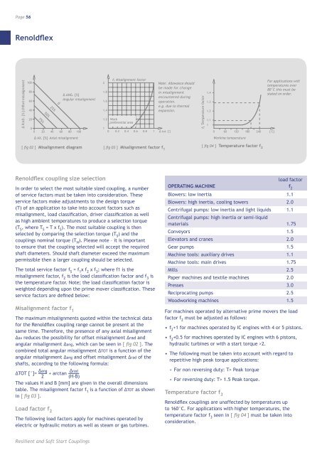
Page 56<strong>Renold</strong>flex∆ R AD. [% ] Offset misalignmen t1008060402075%50%25%00 20 40 60 80 1000∆ ANG. [%]Angular misalignment21.81.61.41.21f 1 Misalignment factorWorkpreferential area0 0.2 0.4 0.6 0.8 1Note: Allowance shouldbe made for changein misalignmentencountered duringoperation.e.g. due to thermalexpansion.∆ tot. [°]f3 Temperature factor1.41.31.21.110 60 120 180 240 [°C]For applications withtemperatures over80˚C this must bestated on order.∆ AX. [%] Axial misalignmentWorking temperature[ fig 02 ] Misalignment diagram [ fig 03 ] Misalignment factor f 1[ fig 04 ] Temperature factor f 2<strong>Renold</strong>flex coupling size selectionIn order to select the most suitable sized coupling, a numberof service factors must be taken into consideration. Theseservice factors make adjustments to the design torque(T) of an application to take into account factors such asmisalignment, load classification, driver classification as wellas high ambient temperatures to produce a selection torque(T S, where T S= T x f S). The most suitable coupling is thenselected by comparing the selection torque (T S) and thecouplings nominal torque (T N). Please note – it is importantto ensure that the coupling selected will accept the requiredshaft diameters. Should shaft diameter exceed the maximumpermissible then a larger coupling should be selected.The total service factor f S= f 1x f 2x f 3; where f1 is themisalignment factor, f 2is the load classification factor and f 3isthe temperature factor. Note; the load classification factor isweighted depending upon the prime mover classification. Theseservice factors are defined below:Misalignment factor f 1The maximum misalignments quoted within the technical datafor the <strong>Renold</strong>flex coupling range cannot be present at thesame time. Therefore, the presence of any axial misalignment∆ax reduces the possibility for offset misalignment ∆rad andangular misalignment ∆ang, which can be seen in [ fig 02 ]. Thecombined total angular misalignment ∆TOT is a function of theangular misalignment ∆ang and offset misalignment ∆rad of theshafts, according to the following formula:∆TOT [°]= ∆ang + arctan ∆rad2(H-B)The values H and B [mm] are given in the overall dimensionstable. The misalignment factor f 1is a function of ∆TOT as shownin [ fig 03 ].Load factor f 2The following load factors apply for machines operated byelectric or hydraulic motors as well as steam or gas turbines.load factorOPERATING MACHINE f 2Blowers: low inertia 1.1Blowers: high inertia, cooling towers 2.0Centrifugal pumps: low inertia and light liquids 1.1Centrifugal pumps: high inertia or semi-liquidmaterials 1.75Conveyors 1.5Elevators and cranes 2.0Gear pumps 1.5Machine tools: auxiliary drives 1.1Machine tools: main drives 1.75Mills 2.5Paper machines and textile machines 2.0Presses 3.0Reciprocating pumps 2.5Woodworking machines 1.5For machines operated by alternative prime movers the loadfactor f 2must be adjusted as follows:• f 2+1 for machines operated by IC engines with 4 or 5 pistons.• f 2+0.5 for machines operated by IC engines with 6 pistons,hydraulic turbines or with a start torque >2.• The following must be taken into account with regard torepetitive high peak torque applications:• For non reversing duty: T> Peak torque• For reversing duty: T> 1.5 Peak torque.Temperature factor f 3<strong>Renold</strong>flex couplings are unaffected by temperatures upto 160°C. For applications with higher temperatures, thetemperature factor f 3seen in [ fig 04 ] must be taken intoconsideration.Resilient and Soft Start Couplings