Download brochure - Renold plc
Download brochure - Renold plc
Download brochure - Renold plc
- No tags were found...

Create successful ePaper yourself
Turn your PDF publications into a flip-book with our unique Google optimized e-Paper software.
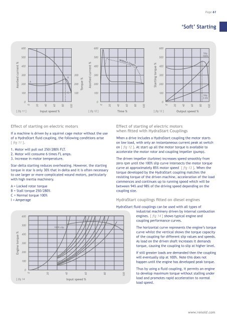
Page 61‘Soft’ Starting600600600500500500Slip100%Without CouplingWithout CouplingAsorbed current %400300200AB300200Torque %Asorbed current %400300200Starting torque %4003002001000C10010001000Slip2-6%020406080100020406080100020406080100[ fig 11 ]Input speed % [ fig 12 ]Time % [ fig 13 ]Output speed %Effect of starting on electric motorsIf a machine is driven by a squirrel cage motor without the useof a HydraStart fluid coupling, the following conditions arise[ fig 11 ].1. Motor will pull out 250/280% FLT.2. Motor will consume 6 times FL amps.3. Increase in motor temperature.Star-delta starting reduces overheating. However, the startingtorque in star is only 30% that in delta and it is often necessaryto use larger or more complicated wound motors, particularlywith high inertia machinery.A = Locked rotor torqueB = Stall torque 250/280%C = Normal torque 100%I = AmperageEngine torque %600500400300200100100% slipEffect of starting of electric motorswhen fitted with HydraStart CouplingsWhen a drive includes a HydraStart coupling the motor startson low load, with only an instantaneous current peak at switchon [ fig 12 ]. At start up all the motor torque is available toaccelerate the motor rotor and coupling impeller (pump).The driven impeller (turbine) increases speed smoothly fromzero rpm until the 100% slip curve intersects the motor torquecurve at approximately 85% motor speed [ fig 13 ]. When thetorque developed by the HydraStart coupling matches theresisting torque of the driven machine, acceleration of the loadcommences and continues up to running speed which will bebetween 94% and 98% of the driving speed depending on thecoupling size.HydraStart couplings fitted on diesel enginesHydraStart fluid couplings can be used with all types ofindustrial machinery driven by internal combustionengines. [ fig 14 ] shows typical engine andcoupling performance curves.The horizontal curve represents the engine’s torquecurve whilst the vertical shows the torque capacityof the coupling for different slip values and speeds.As load on the driven shaft increases it demandstorque, causing the coupling to slip at higher level.If still greater loads are demanded then the couplingwill eventually slip at 100%. Note this does nothappen until the engine has developed peak torque.[ fig 1400204060Input speed %80100Thus by using a fluid coupling, it permits an engineto develop maximum torque without stalling underload and promotes rapid acceleration to normalload speed.www.renold.com