
You also want an ePaper? Increase the reach of your titles
YUMPU automatically turns print PDFs into web optimized ePapers that Google loves.
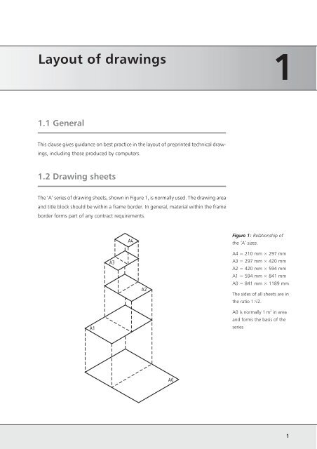
<strong>Layout</strong> <strong>of</strong> <strong>drawings</strong><br />
1.1 General<br />
This clause gives guidance on best practice in the layout <strong>of</strong> preprinted technical draw-<br />
ings, including those produced by computers.<br />
1.2 Drawing sheets<br />
The ‘A’ series <strong>of</strong> drawing sheets, shown in Figure 1, is normally used. The drawing area<br />
and title block should be within a frame border. In general, material within the frame<br />
border forms part <strong>of</strong> any contract requirements.<br />
A1<br />
A3<br />
A4<br />
A2<br />
A0<br />
Figure 1: Relationship <strong>of</strong><br />
the ‘A’ sizes.<br />
1<br />
A4 = 210 mm × 297 mm<br />
A3 = 297 mm × 420 mm<br />
A2 = 420 mm × 594 mm<br />
A1 = 594 mm × 841 mm<br />
A0 = 841 mm × 1189 mm<br />
The sides <strong>of</strong> all sheets are in<br />
the ratio 1:÷2.<br />
A0 is normally 1 m 2 in area<br />
and forms the basis <strong>of</strong> the<br />
series<br />
1
Engineering drawing practice<br />
2<br />
1.3 Title block<br />
The title block for paper sizes A0 to A3 should be situated in the bottom <strong>of</strong> the sheet<br />
and extend to the lower right-hand corner <strong>of</strong> the frame. Only sheets positioned hori-<br />
zontally (landscape) are permitted for these formats. For A4 size paper the title block<br />
may be situated as above (A0 to A3) or can be situated in the shorter (lower) part <strong>of</strong> the<br />
drawing space. Only sheets positioned vertically (portrait) are allowed for this format.<br />
The direction <strong>of</strong> reading <strong>of</strong> the <strong>drawings</strong> is equal to that <strong>of</strong> the title block.<br />
Drawings should include the following basic information in the title blocks:<br />
1.4 Borders and frames<br />
Borders enclosed by the edges <strong>of</strong> the trimmed sheet and the frame limiting the draw-<br />
ing space should be provided with all sizes. The border should be 20 mm wide on the<br />
left edge, including the width <strong>of</strong> the frame. It can be used as a filing margin. All other<br />
borders are 10 mm wide (see Figure 2).<br />
1.5 Drawing formats<br />
Drawing sheets may be produced in two formats. Portrait format is intended to be<br />
viewed with the longest side <strong>of</strong> the sheet vertical (see Figure 3a). Landscape format is<br />
intended to be viewed with the longest side <strong>of</strong> the sheet horizontal (see Figures<br />
3b–3d).<br />
Mandatory information (recommended characters)<br />
Legal owner (unspecified) Date <strong>of</strong> issue (10) Identification number (16)<br />
Sheet number (4) Title (25) Approval person (20)<br />
Creator (20) Document type (assembly, subassembly, detail, etc.) (30)<br />
Optional information (recommended characters)<br />
Revision index (2) Number <strong>of</strong> sheets (4) Responsible department (10)<br />
Document status (20) Paper size (4) Technical reference (20)
1.6 Types <strong>of</strong> <strong>drawings</strong><br />
There are different types <strong>of</strong> <strong>drawings</strong>, two <strong>of</strong> which, detail and assembly type draw-<br />
ings, are shown in Figure 3.<br />
(a)<br />
6<br />
3<br />
(a–c) Detail (single part) <strong>drawings</strong><br />
20<br />
A<br />
5<br />
1 5<br />
10<br />
1. <strong>Layout</strong> <strong>of</strong> <strong>drawings</strong><br />
1 2 4 5 Figure 2: Borders<br />
(b)<br />
(c)<br />
Key:<br />
1 Trimming mark<br />
2 Trimmed format<br />
3 Grid reference<br />
4 Frame <strong>of</strong> drawing space<br />
5 Drawing space<br />
6 Untrimmed format<br />
Dimensions in millimetres<br />
Figure 3: Types <strong>of</strong><br />
<strong>drawings</strong><br />
3
Engineering drawing practice<br />
Figure 3: Contd<br />
4<br />
(d) Assembly drawing<br />
Note. In the case <strong>of</strong> Figure 3(d) a composite drawing is illustrated, i.e. an Assem-<br />
bly and Parts/Item list combined. A Parts/Item list is generally produced as a sepa-<br />
rate document.<br />
There are commonly two types <strong>of</strong> lists, document list and Parts/Item lists, that accom-<br />
pany an assembly drawing and associated detail <strong>drawings</strong>. In general, both lists should<br />
be clearly identified as being associated with the assembly drawing.<br />
A Document or Drawing List should consist <strong>of</strong> a list <strong>of</strong> <strong>drawings</strong> and specifications<br />
references, which are required to build or manufacture the product.<br />
A Parts/Item List should consist <strong>of</strong> a list <strong>of</strong> the physical parts and quantities required to<br />
assemble the product.<br />
4<br />
3<br />
2<br />
1<br />
Note. For further information on item referencing, see Clause 9.<br />
4<br />
3<br />
2<br />
1<br />
TAPER PIN<br />
PIN<br />
PULLEY<br />
BRACKET<br />
ITEM DESCRIPTION NO. OFF<br />
1<br />
1<br />
1<br />
1
1.7 Marking<br />
Technical Product Documentation (TPD) or Technical Product Specification (TPS)<br />
prepared in accordance with the requirements <strong>of</strong> BS 8888 should be marked with the<br />
number <strong>of</strong> the standard, i.e. BS 8888, in a prominent location.<br />
Note. The marking <strong>of</strong> TPD with ‘BS 8888’ constitutes a claim that the appropriate<br />
requirements <strong>of</strong> all relevant cross-referenced standards, in addition to the require-<br />
ments directly stated in BS 8888, have been met.<br />
If the TPD or TPS has been prepared using the independency system <strong>of</strong> tolerancing (see<br />
Clause 14, Tolerancing), the mark identifying the number <strong>of</strong> this standard shall be<br />
supplemented by the letter ‘I’ contained within an equilateral triangle, as shown in<br />
Figure 4.<br />
If the TPD or TPS has been prepared using the dependency system <strong>of</strong> tolerancing (see<br />
Clause 14, Tolerancing), the mark identifying the number <strong>of</strong> this standard shall be<br />
supplemented by the letter ‘D’ contained within an equilateral triangle, as shown in<br />
Figure 5.<br />
BS 8888<br />
BS 8888<br />
I<br />
D<br />
1. <strong>Layout</strong> <strong>of</strong> <strong>drawings</strong><br />
Figure 4: Method <strong>of</strong><br />
indicating that the<br />
independency system <strong>of</strong><br />
tolerancing has been used<br />
Figure 5: Method <strong>of</strong><br />
indicating that the<br />
dependency system <strong>of</strong><br />
tolerancing has been used<br />
5
Engineering drawing practice<br />
6<br />
Relevant standards Title<br />
BS EN ISO 5457 Technical product documentation — Sizes and<br />
layout <strong>of</strong> drawing sheets<br />
BS EN ISO 3098-0 Technical product documentation — Lettering —<br />
Part 0: General requirements<br />
BS EN ISO 5455 Technical <strong>drawings</strong> — Scales<br />
BS ISO 7200 Technical <strong>drawings</strong> — Title blocks<br />
BS ISO 10209-1 Technical product documentation — Vocabulary —<br />
Part 1: Terms relating to technical <strong>drawings</strong> gen-<br />
eral and types <strong>of</strong> <strong>drawings</strong><br />
BS ISO 7573 Technical <strong>drawings</strong> — Item lists<br />
BS 8888 Technical product documentation (TPD) — Specifi-<br />
Associated clauses Title<br />
Clause 2 Scales<br />
cation for defining, specifying and graphically rep-<br />
resenting products<br />
Clause 3 Projection<br />
Clause 4 Lines and terminators<br />
Clause 9 Item references