
Create successful ePaper yourself
Turn your PDF publications into a flip-book with our unique Google optimized e-Paper software.
HAC_C05.qxd 7/24/08 9:35 Page 174<br />
Chapter 5<br />
<strong>Pipe</strong> <strong>sizing</strong><br />
174<br />
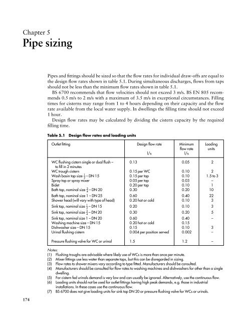
<strong>Pipe</strong>s and fittings should be sized so that the flow rates for individual draw-offs are equal to<br />
the design flow rates shown in table 5.1. During simultaneous discharges, flows from taps<br />
should not be less than the minimum flow rates shown in table 5.1.<br />
BS 6700 recommends that flow velocities should not exceed 3 m/s. BS EN 805 recommends<br />
0.5 m/s to 2 m/s with a maximum of 3.5 m/s in exceptional circumstances. Filling<br />
times for cisterns may range from 1 to 4 hours depending on their capacity and the flow<br />
rate available from the local water supply. In dwellings the filling time should not exceed<br />
1 hour.<br />
Design flow rates may be calculated by dividing the cistern capacity by the required<br />
filling time.<br />
Table 5.1 Design flow rates and loading units<br />
Outlet fitting Design flow rate Minimum Loading<br />
flow rate units<br />
l/s l/s<br />
WC flushing cistern single or dual flush –<br />
to fill in 2 minutes<br />
0.13 0.05 2<br />
WC trough cistern 0.15 per WC 0.10 2<br />
Wash basin tap size 1 – – DN 15 2 0.15 per tap 0.10 1.5 to 3<br />
Spray tap or spray mixer 0.05 per tap 0.03 –<br />
Bidet 0.20 per tap 0.10 1<br />
Bath tap, nominal size 3 – – DN 20 4 0.30 0.20 10<br />
Bath tap, nominal size 1 – DN 25 0.60 0.40 22<br />
Shower head (will vary with type of head) 0.20 hot or cold 0.10 3<br />
Sink tap, nominal size 1 – – DN 15 2 0.20 0.10 3<br />
Sink tap, nominal size 3 – – DN 20 4 0.30 0.20 5<br />
Sink tap, nominal size 1 – DN 20 0.60 0.40 –<br />
Washing machine size – DN 15 0.20 hot or cold 0.15<br />
Dishwasher size – DN 15 0.15 0.10 3<br />
Urinal flushing cistern 0.004 per position served 0.002 –<br />
Pressure flushing valve for WC or urinal 1.5 1.2 –<br />
Notes:<br />
(1) Flushing troughs are advisable where likely use of WCs is more than once per minute.<br />
(2) Mixer fittings use less water than separate taps, but this can be disregarded in <strong>sizing</strong>.<br />
(3) Flow rates to shower mixers vary according to type fitted. Manufacturers should be consulted.<br />
(4) Manufacturers should be consulted for flow rates to washing machines and dishwashers for other than a single<br />
dwelling.<br />
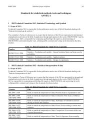
(5) For cistern fed urinals demand is very low and can usually be ignored. Alternatively, use the continuous flow.<br />
(6) Loading units should not be used for outlet fittings having high peak demands, e.g. those in industrial<br />
installations. In these cases use the continuous flow.<br />
(7) BS 6700 does not give loading units for sink tap DN 20 or pressure flushing valve for WCs or urinals.
HAC_C05.qxd 7/24/08 9:35 Page 175<br />
<strong>Pipe</strong> Sizing 175<br />
Correct pipe sizes will ensure adequate flow rates at appliances and avoid problems<br />
caused by over<strong>sizing</strong> and under<strong>sizing</strong>; see figure 5.1.<br />
Over<strong>sizing</strong> will mean:<br />
• additional and unnecessary installation costs;<br />
• delays in obtaining hot water at outlets;<br />
• increased heat losses from hot water distributing pipes.<br />
Under<strong>sizing</strong> may lead to:<br />
• inadequate delivery from outlets and possibly no delivery at some outlets during simultaneous<br />
use;<br />
• some variation in temperature and pressure at outlets, especially showers and other<br />
mixers;<br />
• some increase in noise levels.<br />
Available head = vertical distance in metres from water line<br />
(from cistern) in cistern to point under consideration<br />
= head at main minus height above main<br />
Available head = 20 m – 4 m<br />
(mains supply) = 16 m head<br />
Figure 5.1 <strong>Pipe</strong> <strong>sizing</strong> considerations<br />
head<br />
e.g. 4 m<br />
(b) available head (pressure)<br />
° at the water main<br />
° from the storage cistern<br />
° at point of delivery<br />
main<br />
e.g. 20 m head<br />
(a) flow rate<br />
° through pipe under consideration<br />
° at point of delivery<br />
point of<br />
delivery<br />
head<br />
(c) resistance to flow<br />
through pipes, valves<br />
and fittings<br />
CWSC<br />
In smaller, straightforward installations such as single dwellings, pipes are often sized on<br />
the basis of experience and convention.<br />
In larger and more complex buildings, or with supply pipes that are very long, it is necessary<br />
to use a recognized method of calculation such as that shown in sections 5.1 and 5.2.<br />
head
HAC_C05.qxd 7/24/08 9:35 Page 176<br />
176 Hot and Cold Water Supply<br />
BS EN 806-3 gives an alternative ‘simplified method’ of pipe <strong>sizing</strong> that can be used for<br />
‘standard installations’.<br />
5.1 Sizing procedure for supply pipes<br />
The procedure below is followed by an explanation of each step with appropriate examples.<br />
(1) Assume a pipe diameter.<br />
(2) Determine the flow rate:<br />
(a) by using loading units;<br />
(b) for continuous flows;<br />
(c) obtain the design flow rate by adding (a) and (b).<br />
(3) Determine the effective pipe length:<br />
(d) work out the measured pipe length;<br />
(e) work out the equivalent pipe length for fittings;<br />
(f) work out the equivalent pipe length for draw-offs;<br />
(g) obtain the effective pipe length by adding (d), (e) and (f).<br />
(4) Calculate the permissible loss of head:<br />
(h) determine the available head:<br />
(i) determine the head loss per metre run through pipes;<br />
(j) determine the head loss through fittings;<br />
(k) calculate the permissible head loss.<br />
(5) Determine the pipe diameter:<br />
(l) decide whether the assumed pipe size will give the design flow rate in (c) without<br />
exceeding the permissible head loss in (k).<br />
Explanation of the procedure<br />
Assume a pipe diameter (1)<br />
In pipe <strong>sizing</strong> it is usual to make an assumption of the expected pipe size and then prove<br />
whether or not the assumed size will carry the required flow.<br />
Determine the flow rate (2)<br />
In most buildings it is unlikely that all the appliances installed will be used simultaneously.<br />
As the number of outlets increases the likelihood of them all being used at the same time<br />
decreases. Therefore it is economic sense to design the system for likely peak flows based on<br />
probability theory using loading units, rather than using the possible maximum flow rate.<br />
(a) Loading units. A loading unit is a factor or number given to an appliance which relates<br />
the flow rate at its terminal fitting to the length of time in use and the frequency of use<br />
for a particular type and use of building (probable usage). Loading units for various<br />
appliances are given in table 5.1.<br />
By multiplying the number of each type of appliance by its loading unit and adding<br />
the results, a figure for the total loading units can be obtained. This is converted to a<br />
design flow rate using figure 5.2.<br />
An example using loading units is given in figure 5.3.
HAC_C05.qxd 7/24/08 9:35 Page 177<br />
Loading units<br />
8000 30<br />
5000<br />
2000<br />
1000<br />
500<br />
400<br />
300<br />
200<br />
100<br />
50<br />
20<br />
10<br />
25<br />
20<br />
15<br />
10<br />
8<br />
6<br />
5<br />
4<br />
3<br />
2<br />
1.5<br />
1.0<br />
0.8<br />
0.6<br />
0.5<br />
0.4<br />
0.3<br />
Flow rate in litres per second<br />
Figure 5.2<br />
Conversion<br />
chart – loading<br />
units to flow rate<br />
<strong>Pipe</strong> Sizing 177<br />
(b) Continuous flows. For some appliances, such as automatic flushing cisterns,<br />
the flow rate must be considered as a continuous flow instead of applying<br />
probability theory and using loading units. For such appliances the full<br />
design flow rate for the outlet fitting must be used, as given in table 5.1.<br />
However, in the example shown in figure 5.3, the continuous flow for the<br />
two urinals of 0.008 l/s (from table 5.1) is negligible and can be ignored for<br />
design purposes.<br />
(c) Design flow rate. The design flow rate for a pipe is the sum of the flow rate<br />
determined from loading units (a) and the continuous flows (b).<br />
Determine the effective pipe length (3)<br />
(d) Find the measured pipe length. Figure 5.4 is an example showing how the<br />
measured pipe length is found.<br />
6 wash basins<br />
6 wash basins<br />
5 WCs<br />
5 WCs<br />
12 wash basins × 11 – 2 = 18<br />
10 WCs × 2 = 20<br />
2 urinal bowls × — = —<br />
2 cleaners’ sinks × 3 = 6<br />
Total loading units 44<br />
2 urinal bowls<br />
cleaners’ sink<br />
sink<br />
Therefore, from figure 5.2, the required flow rate for the system is 0.7 l/s.<br />
Figure 5.3 Example of use of loading units<br />
Assumed pipe diameter 20 mm.<br />
double check valve<br />
assembly<br />
stopvalve<br />
0.5 m<br />
3 m<br />
1 m<br />
elbows<br />
Note There is no need to consider both branch pipes to taps.<br />
Figure 5.4 Example of measured pipe length<br />
pipe bend<br />
draw<br />
off<br />
taps<br />
0.25 m<br />
Measured pipe length 4.75 m.
HAC_C05.qxd 7/24/08 9:35 Page 178<br />
178 Hot and Cold Water Supply<br />
Table 5.2 Equivalent pipe lengths (copper, stainless steel and plastics)<br />
Bore of pipe Equivalent pipe length<br />
Elbow Tee Stopvalve Check valve<br />
mm m m m m<br />
12 0.5 0.6 4.0 2.5<br />
20 0.8 1.0 7.0 4.3<br />
25 1.0 1.5 10.0 5.6<br />
32 1.4 2.0 13.0 6.0<br />
40 1.7 2.5 16.0 7.9<br />
50 2.3 3.5 22.0 11.5<br />
65 3.0 4.5 – –<br />
73 3.4 5.8 34.0 –<br />
Notes:<br />
(1) For tees consider change of direction only. For gate valves losses are insignificant.<br />
(2) For fittings not shown, consult manufacturers if significant head losses are expected.<br />
(3) For galvanized steel pipes in a small installation, pipe <strong>sizing</strong> calculations may be based on the data in this<br />
table for equivalent nominal sizes of smooth bore pipes. For larger installations, data relating specifically to<br />
galvanized steel should be used. BS 6700 refers to suitable data in the Plumbing Engineering Services Design<br />
Guide published by the Institute of Plumbing.<br />
(e, f) Find the equivalent pipe lengths for fittings and draw-offs. For convenience the<br />
frictional resistances to flow through fittings are expressed in terms of pipe lengths<br />
having the same resistance to flow as the fitting. Hence the term ‘equivalent pipe length’<br />
(see table 5.2).<br />
For example, a 20 mm elbow offers the same resistance to flow as a 20 mm pipe<br />
0.8 m long.<br />
Figure 5.5 shows the equivalent pipe lengths for the fittings in the example in figure 5.4.<br />
(g) Effective pipe length. The effective pipe length is the sum of the measured pipe length<br />
(d) and the equivalent pipe lengths for fittings (e) and draw-offs (f).<br />
Therefore, for the example shown in figure 5.4 the effective pipe length would be:<br />
Measured pipe length<br />
Equivalent pipe lengths<br />
4.75 m<br />
elbows 2 × 0.8 = 1.6 m<br />
tee 1 × 1.0 = 1.0 m<br />
stopvalve1 × 7.0 = 7.0 m<br />
taps 2 × 3.7 = 7.4 m<br />
check valves 2 × 4.3 = 8.6 m<br />
Effective pipe length = 30.35 m<br />
Permissible loss of head (pressure) (4)<br />
Pressure can be expressed in the following ways.<br />
(i) In pascals, the pascal (Pa) being the SI unit for pressure.<br />
(ii) As force per unit area, N/m 2 .<br />
1 N/m 2 = 1 pascal (Pa).
HAC_C05.qxd 7/24/08 9:35 Page 179<br />
Using the example from figure 5.4:<br />
20 mm elbow = 0.8 m pipe length<br />
20 mm tee = 1.0 m pipe length<br />
Figure 5.5 Examples of equivalent pipe lengths<br />
20 mm draw-off tap = 3.7 m pipe length<br />
20 mm stopvalve = 7.0 m pipe length<br />
20 mm check valve = 4.3 m pipe length<br />
<strong>Pipe</strong> Sizing 179<br />
(iii) As a multiple of atmospheric pressure (bar).<br />
Atmospheric pressure = 100 kN/m 2 = 100 kPa = 1 bar.<br />
(iv) As metres head, that is, the height of the water column from the water level to the<br />
draw-off point.<br />
1 m head = 9.81 kN/m 2 = 9.81 kPa = 98.1 mb.<br />
In the <strong>sizing</strong> of pipes, any of these units can be used. BS 6700 favours the pascal. However,<br />
this book retains the use of metres head, giving a more visual indication of pressure that<br />
compares readily to the height and position of fittings and storage vessels in the building.<br />
(h) Available head. This is the static head or pressure at the pipe or fitting under consideration,<br />
measured in metres head (see figure 5.1).<br />
(i) Head loss through pipes. The loss of head (pressure) through pipes due to frictional<br />
resistance to water flow is directly related to the length of the pipe run and the diameter<br />
of the pipe. <strong>Pipe</strong>s of different materials will have different head losses, depending<br />
on the roughness of the bore of the pipe and on the water temperature. Copper,<br />
stainless steel and plastics pipes have smooth bores and only pipes of these materials<br />
are considered in this section.<br />
(j) Head loss through fittings. In some cases it is preferable to subtract the likely resistances<br />
in fittings (particularly draw-offs) from the available head, rather than using<br />
equivalent pipe lengths.<br />
Table 5.3 gives typical head losses in taps for average flows compared with equivalent<br />
pipe lengths. Figures 5.6 and 5.7 provide a method for determining head<br />
losses through stopvalves and float-operated valves respectively.<br />
Note Where meters are installed in a pipeline the loss of head through the meter<br />
should be deducted from the available head.
HAC_C05.qxd 7/24/08 9:35 Page 180<br />
180 Hot and Cold Water Supply<br />
Table 5.3 Typical head losses and equivalent pipe lengths for taps<br />
Nominal size of tap Flow rate Head loss Equivalent<br />
pipe length<br />
l/s m m<br />
G 1 – – DN 15 2 0.15 0.5 3.7<br />
G 1 – – DN 15 2 0.20 0.8 3.7<br />
G 3 – – DN 20 4 0.30 0.8 11.8<br />
G 1 – DN 25 0.60 1.5 22.0<br />
8<br />
7<br />
6<br />
5<br />
4<br />
3<br />
2<br />
1<br />
0.9<br />
0.8<br />
0.7<br />
0.6<br />
0.5<br />
0.4<br />
0.3<br />
0.2<br />
0.1<br />
0.09<br />
0.08<br />
0.07<br />
0.06<br />
0.05<br />
Head loss in metres (wall friction gradient)<br />
10<br />
8<br />
6<br />
5<br />
4<br />
3<br />
2<br />
1<br />
0.8<br />
0.6<br />
0.5<br />
0.4<br />
0.3<br />
0.2<br />
0.1<br />
0.08<br />
0.06<br />
0.05<br />
0.04<br />
0.03<br />
Note Gate valves and spherical plug valves offer little or no resistance<br />
to flow provided they are fully open.<br />
Figure 5.6 Head loss through stopvalves<br />
Flow in litres per second<br />
2<br />
1 1 /2<br />
1 1 /4<br />
1<br />
3 /4<br />
1 /2<br />
Nominal size of stopvalve
HAC_C05.qxd 7/24/08 9:35 Page 181<br />
0.5<br />
0.6<br />
0.7<br />
0.8<br />
1<br />
2<br />
3<br />
4<br />
5<br />
6<br />
7<br />
8<br />
10<br />
11<br />
(pressure)<br />
20 metres in<br />
25<br />
30<br />
water of<br />
40<br />
50 Head<br />
Based on Q = AV 0.75<br />
V = 2gH<br />
where<br />
Diameter of orifice<br />
Millimetres<br />
35<br />
30<br />
25<br />
20<br />
15<br />
10<br />
8<br />
6<br />
5<br />
4<br />
3<br />
Inches<br />
1 1 /4<br />
1<br />
15 /16<br />
3 /4<br />
5 /8<br />
1 /2<br />
3 /8<br />
1 /4<br />
3 /16<br />
1 /8<br />
20<br />
15<br />
10<br />
8<br />
6<br />
5<br />
4<br />
3<br />
2<br />
1<br />
0.8<br />
0.6<br />
0.5<br />
0.4<br />
0.3<br />
0.2<br />
0.1<br />
0.08<br />
0.06<br />
0.05<br />
0.04<br />
0.03<br />
0.02<br />
0.01<br />
Q is flow (l/s)<br />
A is cross sectional area of pipe (m 2 )<br />
V is velocity (m/s)<br />
g is acceleration due to gravity (m/s 2 )<br />
H is head of water (m)<br />
Figure 5.7 Head loss through float-operated valves<br />
Flow through orifice in litres per second<br />
<strong>Pipe</strong> Sizing 181
HAC_C05.qxd 7/24/08 9:35 Page 182<br />
182 Hot and Cold Water Supply<br />
(k) Permissible head loss. This relates the available head to the frictional resistances in the<br />
pipeline. The relationship is given by the formula:<br />
Available head (m)<br />
Permissible head loss (m/m run) =<br />
Effective pipe length (m)<br />
This formula is used to determine whether the frictional resistance in a pipe will permit<br />
the required flow rate without too much loss of head or pressure. Figure 5.8 illustrates<br />
the permissible head loss for the example in figure 5.4.<br />
double check valve<br />
assembly<br />
elbows<br />
stopvalve<br />
Figure 5.8 Example of permissible head loss<br />
Pressure at taps 45 m head<br />
tee pipe bend<br />
20 mm pipeline<br />
Flow rate for 2 taps 0.4 l/s<br />
draw-off<br />
taps<br />
Permissible head loss =<br />
available head (45 m)<br />
effective pipe length (30.55 m)<br />
= 1.48 m/m run<br />
Determine the pipe diameter (5)<br />
In the example in figure 5.4 a pipe size of 20 mm has been assumed. This pipe size must give<br />
the design flow rate without the permissible head loss being exceeded. If it does not, a fresh<br />
pipe size must be assumed and the procedure worked through again.<br />
Figure 5.9 relates pipe size to flow rate, flow velocity and head loss. Knowing the<br />
assumed pipe size and the calculated design flow rate, the flow velocity and the head loss<br />
can be found from the figure as follows.<br />
(1) Draw a line joining the assumed pipe size (20 mm) and the design flow rate (0.4 l/s).<br />
(2) Continue this line across the velocity and head loss scales.<br />
(3) Check that the loss of head (0.12 m/m run) does not exceed the calculated permissible<br />
head loss of 1.48 m/m run.<br />
(4) Check that the flow velocity (1.4 m/s) is not too high by referring to table 5.4.
HAC_C05.qxd 7/24/08 9:35 Page 183<br />
1<br />
0.80<br />
0.60<br />
0.50<br />
0.40<br />
0.30<br />
0.20<br />
0.10<br />
0.08<br />
0.06<br />
0.05<br />
0.04<br />
0.03<br />
0.02<br />
0.01<br />
0.008<br />
0.007<br />
0.006<br />
0.005<br />
0.004<br />
0.003<br />
0.002<br />
0.001<br />
run<br />
0.0008<br />
0.0006metre<br />
0.0005<br />
per<br />
0.0004<br />
0.0003<br />
metres in<br />
0.0002<br />
loss<br />
0.0001Head 6<br />
5<br />
4<br />
3<br />
2.5<br />
2<br />
1.5<br />
1.0<br />
0.75<br />
0.5<br />
0.25<br />
0.1<br />
Velocity in metres per second<br />
Formula applied between these limits only<br />
50<br />
40<br />
30<br />
Lamont‘s smooth pipe formula S3:<br />
V = 0.5545 d 0.6935 i 0.5645<br />
Where V is velocity (m/s)<br />
d is diameter (mm)<br />
i is hydraulic gradient<br />
Figure 5.9 Determination of pipe diameter<br />
20<br />
10<br />
8<br />
6<br />
5<br />
4<br />
3<br />
2<br />
1.0<br />
0.8<br />
0.6<br />
0.5<br />
0.4<br />
0.3<br />
0.2<br />
0.1<br />
0.08<br />
0.06<br />
0.05<br />
Flow in litres per second<br />
Outside diameter of copper pipe in millimetres<br />
<strong>Pipe</strong> Sizing 183<br />
76.1<br />
6<br />
Notes Figures shown are for cold water at 12°C.<br />
Hot water will show slightly more favourable head loss results.<br />
BS 6700 gives head loss in kPa.<br />
1 m head = 9.81 kPa.<br />
67<br />
54<br />
42<br />
35<br />
28<br />
22<br />
18<br />
15<br />
12<br />
10<br />
8<br />
80<br />
75<br />
70<br />
65<br />
60<br />
55<br />
50<br />
45<br />
40<br />
35<br />
30<br />
25<br />
20<br />
15<br />
10<br />
5<br />
Actual bore of pipe in millimetres
HAC_C05.qxd 7/24/08 9:35 Page 184<br />
184 Hot and Cold Water Supply<br />
Table 5.4 Maximum recommended flow velocities<br />
Water temperature Flow velocity<br />
5.2 Tabular method of pipe <strong>sizing</strong><br />
<strong>Pipe</strong> <strong>sizing</strong> in larger and more complicated buildings is perhaps best done by using a simplified<br />
tabular procedure. BS 6700 gives examples of this but for more detailed data readers<br />
should refer to the Institute of Plumbing’s Plumbing Engineering Services Design Guide.<br />
The data used in the tabular method that follows are taken from BS 6700 but the author<br />
has simplified the method compared with that given in the standard.<br />
The tabular method uses a work sheet which can be completed as each of the steps<br />
is followed in the pipe <strong>sizing</strong> procedure. An example of the method follows with some<br />
explanation of each step.<br />
Explanation of the tabular method<br />
<strong>Pipe</strong>s readily <strong>Pipe</strong>s not readily<br />
accessible accessible<br />
°C m/s m/s<br />
10 3.0 2.0<br />
50 3.0 1.5<br />
70 2.5 1.3<br />
90 2.0 1.0<br />
Note Flow velocities should be limited to reduce system noise.<br />
<strong>Pipe</strong>work diagram<br />
(1) Make a diagram of the pipeline or system to be considered (see figure 5.10).<br />
(2) Number the pipes beginning at the point of least head, numbering the main pipe run<br />
first, then the branch pipes.<br />
(3) Make a table to show the loading units and flow rates for each stage of the main run.<br />
Calculate and enter loading units and flow rates; see figure 5.10.<br />
Calculate flow demand<br />
(1) Calculate maximum demand (see figure 5.10):<br />
• add up loading units for each stage (each floor level);<br />
• convert loading units to flow rates;<br />
• add up flow rates for each stage.<br />
(2) Calculate probable demand (see figure 5.10):<br />
• add up loading units for all stages;<br />
• convert total loading units to flow rate.<br />
(3) Calculate percentage demand (number of stages for which frictional resistances need<br />
be allowed). See figure 5.12.
HAC_C05.qxd 7/24/08 9:35 Page 185<br />
Work through the calculation sheet<br />
See figure 5.11, using the data shown in figures 5.10 and 5.12.<br />
2.8 m<br />
2.4 m<br />
2.4 m<br />
1 m<br />
2.4 m<br />
1 m<br />
1<br />
2<br />
3<br />
4<br />
tap<br />
0.5<br />
m<br />
CWSC<br />
servicing valves<br />
double check valve<br />
assembly<br />
5<br />
2 m<br />
3 m<br />
7<br />
2 m<br />
Bib tap at 0.3 l/s in frequent use.<br />
wc wb b<br />
0.5 m<br />
6<br />
sink<br />
1 m<br />
1 m<br />
0.5<br />
1 m<br />
Assume draw-offs on each branch<br />
all to be at the same level.<br />
Size for largest draw-off at each<br />
branch, i.e. bath.<br />
wc wb b<br />
1 m<br />
0.5 m<br />
loading<br />
units<br />
+<br />
+<br />
+<br />
=<br />
2<br />
1.5<br />
10<br />
16.5<br />
30<br />
3<br />
+ 13.5<br />
= 16.5<br />
2<br />
+ 1.5<br />
+ 10<br />
= 13.5<br />
litres per<br />
second<br />
0.55<br />
+ 0.3<br />
= 0.85 l/s<br />
0.4<br />
+ 0.3<br />
= 0.7 l/s<br />
0.35<br />
+ 0.3<br />
= 0.65 l/s<br />
0.3 l/s<br />
Note Figure is not to scale for convenience, water level in<br />
cistern taken to be at base of cistern. Servicing valves assumed<br />
to be full-flow gate valves having no head losses.<br />
Refer also to figure 5.12.<br />
Figure 5.10 <strong>Pipe</strong> <strong>sizing</strong> diagram<br />
<strong>Pipe</strong> Sizing 185
HAC_C05.qxd 7/24/08 9:35 Page 186<br />
186 Hot and Cold Water Supply<br />
Calculation sheet<br />
(1) <strong>Pipe</strong><br />
reference<br />
Enter pipe reference on calculation sheet<br />
(2) Loading<br />
units<br />
Determine loading unit<br />
(table 5.1)<br />
This is an example of a suitable calculation sheet with explanatory notes.<br />
(3) Flow rate<br />
(l/s)<br />
Convert loading units to flow rate<br />
(figure 5.2)<br />
(4) <strong>Pipe</strong> size<br />
(mm diameter)<br />
Make assumption as to pipe size<br />
(inside diameter)<br />
(5) Loss of head<br />
(m/m run)<br />
Work out frictional resistance per metre<br />
(figure 5.9)<br />
(6) Flow velocity<br />
(m/s)<br />
Determine velocity of flow<br />
(figure 5.9)<br />
(7) Measured pipe<br />
run (m)<br />
Measure length of pipe under consideration<br />
Figure 5.11 Calculation sheet – explanation of use<br />
(8) Equivalent pipe<br />
length (m)<br />
Consider frictional resistances in fittings<br />
(table 5.2 and figures 5.6 and 5.7)<br />
(9) Effective pipe<br />
length (m)<br />
Add totals in columns 7 and 8<br />
(10) Head consumed<br />
(m)<br />
Head consumed – multiply column 5 by column 9<br />
(11) Progressive<br />
head (m)<br />
Add head consumed in column 10 to progressive<br />
head in previous row of column 11<br />
(12) Available<br />
head (m)<br />
Record available head at point of delivery<br />
(13) Final pipe<br />
size (mm)<br />
Compare progressive head with available<br />
head to confirm pipe diameter or not<br />
Note If, for any pipe or series of pipes, it is found that the<br />
assumed pipe size gives a progressive head that is in<br />
excess of the available head, or is noticeably low, it will be<br />
necessary to repeat the <strong>sizing</strong> operation using a revised<br />
assumed pipe diameter.<br />
(14) Remarks<br />
Notes
HAC_C05.qxd 7/24/08 9:35 Page 187<br />
Calculation sheet<br />
(1) <strong>Pipe</strong><br />
reference<br />
1<br />
5<br />
2<br />
6<br />
3<br />
7<br />
4<br />
(2) Loading<br />
units<br />
30<br />
13.5<br />
16.5<br />
3<br />
13.5<br />
13.5<br />
—<br />
(3) Flow rate<br />
(l/s)<br />
0.85<br />
0.35<br />
0.7<br />
0.3<br />
0.65<br />
0.35<br />
0.3<br />
(4) <strong>Pipe</strong> size<br />
(mm diameter)<br />
Refer also to figure 5.10.<br />
Estimated maximum demand = 1.4 l/s<br />
Probable demand = 0.85 l/s<br />
probable demand 100<br />
Percentage demand = ×<br />
estimated maximum demand 1<br />
32<br />
20<br />
25<br />
20<br />
25<br />
20<br />
20<br />
(5) Loss of head<br />
(m/m run)<br />
0.05<br />
0.095<br />
0.12<br />
0.07<br />
0.1<br />
0.095<br />
0.07<br />
(6) Flow velocity<br />
(m/s)<br />
1.2<br />
1.25<br />
1.5<br />
1.0<br />
1.4<br />
1.25<br />
1.0<br />
Figure 5.12 Calculation sheet – example of use<br />
0.85 100<br />
= × =60%<br />
1.4 1<br />
Therefore only 60% of the installation need be considered.<br />
For example, if we were designing for a multi-storey building<br />
20 storeys high, only the first 12 storeys need to be calculated.<br />
However, in the example followed here, the whole system has<br />
been sized because the last fitting on the run has a high flow rate<br />
in continuous use.<br />
For branches only the pipes to the largest draw-off, i.e. the bath<br />
tap, need be sized.<br />
(7) Measured pipe<br />
run (m)<br />
2.8<br />
5.5<br />
2.4<br />
3.5<br />
2.4<br />
5.5<br />
2.9<br />
(8) Equivalent pipe<br />
length (m)<br />
1.4<br />
12.0<br />
–<br />
10.4<br />
–<br />
12.0<br />
1.6<br />
(9) Effective pipe<br />
length (m)<br />
4.2<br />
17.5<br />
2.4<br />
13.9<br />
2.4<br />
17.5<br />
4.5<br />
(10) Head consumed<br />
(m)<br />
0.21<br />
1.66<br />
0.29<br />
0.97<br />
0.24<br />
1.66<br />
0.31<br />
(11) Progressive<br />
head (m)<br />
0.21<br />
1.87<br />
2.16<br />
3.13<br />
3.37<br />
5.03<br />
5.34<br />
(12) Available<br />
head (m)<br />
2.8<br />
3.3<br />
5.2<br />
5.7<br />
7.6<br />
8.1<br />
10.0<br />
<strong>Pipe</strong> Sizing 187<br />
(13) Final pipe<br />
size (mm)<br />
32<br />
20<br />
25<br />
20<br />
25<br />
20<br />
20<br />
(14) Remarks
HAC_C05.qxd 7/24/08 9:35 Page 188<br />
188 Hot and Cold Water Supply<br />
5.3 Sizing cold water storage<br />
In Britain, cold water has traditionally been stored in both domestic and non-domestic<br />
buildings, to provide a reserve of water in case of mains failure. However, in recent years<br />
we have seen an increase in the use of ‘direct’ pressure systems, particularly for hot water<br />
services where many combination boilers and unvented hot water storage vessels are now<br />
being installed.<br />
BS 6700 no longer gives storage capacities for houses. The following figures are based on<br />
the 1997 edition.<br />
Smaller houses cistern supplying cold water only – 100 l to 150 l<br />
cistern supplying hot and cold outlets – 200 l to 300 l<br />
Larger houses per person where cistern fills only – 80 l<br />
at night per person – 130 l<br />
However, in clause 5.3.9.4 it recommends a minimum storage capacity of 230 l where the<br />
cistern supplies both cold water outlets and hot water apparatus, which was a requirement<br />
of byelaws in the past. The author still favours the old byelaw requirements, which are<br />
more specific and which still seem to be the normal capacity installed.<br />
Cold water storage cistern – 115 l minimum<br />
Feed cistern – No minimum but should be equal to the<br />
capacity of the hot store vessel supplied<br />
Combined feed and storage cistern – 230 l minimum<br />
For larger buildings the capacity of the cold water storage cistern depends on:<br />
• type and use of buildings;<br />
• number of occupants;<br />
• type and number of fittings;<br />
• frequency and pattern of use;<br />
• likelihood and frequency of breakdown of supply.<br />
These factors have been taken into account in table 5.5, which sets out minimum storage<br />
capacities in various types of building to provide a 24-hour reserve capacity in case of<br />
mains failure.<br />
Calculation of minimum cold water storage capacity<br />
Determine the amount of cold water storage required to cover 24 hours interruption<br />
of supply in a combined hotel and restaurant. Number of hotel guests 75, number of<br />
restaurant guests 350.<br />
Storage capacity = number of guests × storage per person from table 5.5<br />
Hotel storage capacity = 75 × 200 = 15 000 l<br />
Restaurant storage capacity = 350 × 7 = 2450 l<br />
Therefore total storage capacity required is 15 000 l + 2450 l = 17 450 l
HAC_C05.qxd 7/24/08 9:35 Page 189<br />
Assuming 12-hour fill time, the design flow rate to the cistern would be:<br />
Design flow rate = 17 450 l cistern capacity ÷ 12 hours<br />
= 17 540 ÷ (12 × 3600 seconds)<br />
= 0.4 l/s<br />
<strong>Pipe</strong> Sizing 189<br />
Table 5.5 Recommended minimum storage of hot and cold water for domestic purposes<br />
Type of building Minimum cold Minimum hot<br />
water storage water storage<br />
litres (l) litres (l)<br />
Hostel 90 per bed space 32 per bed space<br />
Hotel<br />
Office premises:<br />
200 per bed space 45 per bed space<br />
with canteen facilities 45 per employee 4.5 per employee<br />
without canteen facilities 40 per employee 4.0 per employee<br />
Restaurant<br />
Day school:<br />
7 per meal 3.5 per meal<br />
nursery #<br />
primary $<br />
15 per pupil 4.5 per pupil<br />
secondary #<br />
technical $<br />
20 per pupil 5.0 per pupil<br />
Boarding school<br />
Children’s home or<br />
90 per pupil 23 per pupil<br />
residential nursery 135 per bed space 25 per bed space<br />
Nurses’ home 120 per bed space 45 per bed space<br />
Nursing or convalescent home 135 per bed space 45 per bed space<br />
Note Minimum cold water storage shown includes that used to supply hot water outlets.<br />
5.4 Sizing hot water storage<br />
Minimum hot water storage capacities for dwellings, from BS 6700, are:<br />
• 35 l to 45 l per occupant, unless the heat source provides a quick recovery rate;<br />
• 100 l for systems heated by solid fuel boilers;<br />
• 200 l for systems heated by off-peak electricity.<br />
The feed cistern should have a capacity at least equal to that of the hot storage vessel.<br />
Information on storage capacities for larger buildings is given in table 5.5 using data<br />
based on the Institute of Plumbing’s Plumbing Engineering Services Design Guide. The<br />
calculations are similar to those in section 5.3 for the minimum cold water storage capacity<br />
in larger buildings, and require the number of people to be multiplied by the storage per<br />
person, shown in table 5.5.<br />
BS 6700 takes a different approach to the <strong>sizing</strong> of hot water storage and suggests that<br />
when <strong>sizing</strong> hot water storage for any installation, account must be taken of the following:<br />
• pattern of use;<br />
• rate of heat input to the stored water (see table 5.6);
HAC_C05.qxd 7/24/08 9:35 Page 190<br />
190 Hot and Cold Water Supply<br />
• recovery period for the hot store vessel;<br />
• any stratification of the stored water.<br />
Table 5.6 Typical heat input values<br />
Appliance Heat input kW<br />
Electric immersion heater 3<br />
Gas-fired circulator 3<br />
Small boiler and direct cylinder 6<br />
Medium boiler and indirect cylinder 10<br />
Directly gas-fired storage hot water heater (domestic type) 10<br />
Large domestic boiler and indirect cylinder 15<br />
Stratification (see figure 3.41) means that the hot water in the storage vessel floats on a<br />
layer of cold feed water. This enables hot water to be drawn from the storage vessel without<br />
the incoming cold feed water mixing appreciably with the remaining hot water. In turn,<br />
this allows a later draw-off of water at a temperature close to the design storage temperature,<br />
with less frequent reheating of the contents of the storage vessel and savings in heating<br />
costs and energy.<br />
Stratification is most effective when cylinders and tanks are installed vertically rather<br />
than horizontally, with a ratio of height to width or diameter of at least 2:1.<br />
The cold feed inlet should be arranged to minimize agitation and hence mixing, by being<br />
of ample size and, if necessary, fitted with a baffle to spread the incoming water.<br />
Stratification is used to good effect in off-peak electric water heaters (see figure 5.13). In<br />
this case no heat is normally added to the water during the daytime use and consequently<br />
very little mixing of hot and cold water takes place. In other arrangements the heating of<br />
the water will induce some mixing.<br />
Calculation of hot water storage capacity<br />
As noted above, the storage capacity required in any situation depends on the rate of heat<br />
input to the stored hot water and on the pattern of use. For calculating the required storage<br />
capacity BS 6700 provides a formula for the time M (in min) taken to heat a quantity of<br />
water through a specified temperature rise:<br />
M = VT/(14.3P)<br />
where<br />
V is the volume of water heated (in l);<br />
T is the temperature rise (in °C);<br />
P is the rate of heat input to the water (in kW).<br />
This formula can be applied to any pattern of use and whether stratification of the stored<br />
water takes place or not. It ignores heat losses from the hot water storage vessel, since over<br />
the relatively short times involved in reheating water after a draw-off has taken place, their<br />
effect is usually small.
HAC_C05.qxd 7/24/08 9:35 Page 191<br />
hot<br />
warm<br />
cold<br />
more even<br />
temperature<br />
throughout<br />
cylinder<br />
hot at top<br />
warm<br />
cold at bottom<br />
Figure 5.13 Effects of stratification<br />
<strong>Pipe</strong> Sizing 191<br />
The application of this formula to the <strong>sizing</strong> of hot water cylinders is best illustrated by<br />
the following examples, in which figures have been rounded.<br />
In these examples a small dwelling with one bath installed has been assumed. Maximum<br />
requirement: 1 bath (60 l at 60°C plus 40 l cold water) plus 10 l hot water at 60°C for<br />
kitchen use, followed by a second bath fill after 25 min.<br />
Thus a draw-off of 70 l at 60°C is required, followed after 25 min by 100 l at 40°C,<br />
which may be achieved by mixing hot at 60°C with cold at 10°C.<br />
Example 1 Assuming good stratification<br />
Good stratification could be obtained, for example, by heating with a top entry immersion<br />
heater. With a rate of heat input of 3 kW, the time to heat the 60 l for the second bath<br />
from 10°C to 60°C is:<br />
M = VT/(14.3P)<br />
M = (60 × 50)/(14.3 × 3)<br />
M = 70 min<br />
(a) Bottom entry heater<br />
With a bottom entry immersion heater mixing will occur when<br />
the water is being heated.<br />
(b) Top entry heater<br />
With top entry immersion heater stratification will prevent<br />
mixing.<br />
(c) Twin entry immersion heater<br />
With a twin entry immersion heater the top entry element can<br />
provide economical energy consumption for normal use with<br />
the bottom entry element operating when large quantities of<br />
water are needed, for example, for bathing and washing.<br />
With off-peak heaters the top element can be brought into use<br />
during on-peak periods when needed to top up hot water, and<br />
stratification will ensure that on-peak electricity is not used to<br />
excess.
HAC_C05.qxd 7/24/08 9:35 Page 192<br />
192 Hot and Cold Water Supply<br />
Since the second bath is required after 25 min, it has to be provided from storage. But in the<br />
25 min the volume of water heated to 60°C is:<br />
V = M (14.3)/T<br />
V = (25 × 14.3 × 3)/50<br />
V = 21 l<br />
Therefore the minimum required storage capacity is:<br />
70 + 6 − 21 = 109 l<br />
Example 2 Assuming good mixing of the stored water<br />
Good mixing of the stored water would occur, for example, with heating by a primary coil<br />
in an indirect cylinder.<br />
Immediately after drawing off 70 l at 60°C for the first bath and kitchen use, the heat<br />
energy in the remaining water plus the heat energy in the 70 l replacement at 10°C equals<br />
the heat energy of the water in the full cylinder.<br />
The heat energy of a quantity of water is the product of its volume and temperature.<br />
Then, if V is the minimum size of the storage cylinder and T is the water temperature in the<br />
cylinder after refilling with 70 l at 10°C:<br />
(V − 70) × 60 + (70 × 10) = VT<br />
T = (60V − 4200 + 700)/V<br />
T = (60V − 3500)/V<br />
T = 60 − 3500/V<br />
The second bath is required after 25 min. Hence, with a rate of heat input of 3 kW:<br />
25 = VT/(14.3 × 3)<br />
and the temperature rise T = (25 × 14.3 × 3)/V<br />
and T = 1072.5/V<br />
A temperature of at least 40°C is required to run the second bath. Therefore the water<br />
temperature of the refilled cylinder after the first draw-off of 70 l, plus the temperature rise<br />
after 25 min, must be at least 40°C, or:<br />
(60 − 3500/V) + (1072.5V) = 40 (or more)<br />
60 − 2427.5/V = 40<br />
20 = 2427.5/V<br />
V = 122 l<br />
These calculations, which may be carried out for any situation, show the value of promoting<br />
stratification wherever possible. They also show the savings in storage capacity that can<br />
be made, without affecting the quality of service to the user, by increasing the rate of heat<br />
input to the water. Results of similar calculations are shown in table 5.7 and are taken from<br />
BS 6700.
HAC_C05.qxd 7/24/08 9:35 Page 193<br />
Table 5.7 Hot water storage vessels – minimum capacities<br />
5.5 Legionella – implications in <strong>sizing</strong> storage<br />
<strong>Pipe</strong> Sizing 193<br />
Heat input Dwelling with 1 bath Dwelling with 2 baths*<br />
to water<br />
With With With With<br />
stratification mixing stratification mixing<br />
kW litres (l) litres (l) litres (l) litres (l)<br />
3 109 122 165 260<br />
6 88 88 140 200<br />
10 70 70 130 130<br />
15 70 70 120 130<br />
Note * Maximum requirement of 130 l drawn off at 60°C (2 baths plus 10 l for kitchen use) followed by a<br />
further bath (100 l at 40°C) after 30 min.<br />
It has been common practice in the past for water suppliers to recommend cold water<br />
storage capacities to provide for 24 hours of interruption in supply. Table 5.5 in this book<br />
and Table 1 of BS 6700 reflect this practice.<br />
Recent investigations into the cause and prevention of Legionella contamination suggest<br />
that hot and cold water storage should be sized to cope with peak demand only, and that in<br />
the past, storage vessels have often been over-sized.<br />
Reduced storage capacities would mean quicker turnover of water and less opportunity<br />
for Legionella and other organisms to flourish.<br />
Stratification in hot water can lead to ideal conditions for bacteria to multiply, as the<br />
base of some cylinders often remains within the 20°C temperature range. The base of the<br />
cylinder may also contain sediment and hard water scale which provide an ideal breeding<br />
ground for bacteria.<br />
Where, however, good mixing occurs, higher temperatures can be obtained at the cylinder<br />
base during heating up periods. This is helpful because Legionella will not thrive for more<br />
than 5 minutes at 60°C and are killed instantly at temperatures of 70°C or more.