Parametrically Excited van der Pol Oscillators Coupled by a Resistor
Parametrically Excited van der Pol Oscillators Coupled by a Resistor
Parametrically Excited van der Pol Oscillators Coupled by a Resistor
- No tags were found...

You also want an ePaper? Increase the reach of your titles
YUMPU automatically turns print PDFs into web optimized ePapers that Google loves.
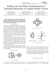
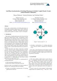
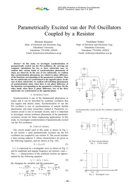
2007 IEEE Workshop on Nonlinear Circuit NetworksNCN'07, Tokushima, Japan, Dec 7--8, 2007<strong>Parametrically</strong> <strong>Excited</strong> <strong>van</strong> <strong>der</strong> <strong>Pol</strong> <strong>Oscillators</strong><strong>Coupled</strong> <strong>by</strong> a <strong>Resistor</strong>Hironori KumenoDept. of Electrical and Electronic Eng.,Tokushima University,Tokushima 770-8506, JAPANEmail: kumeno@ee.tokushima-u.ac.jpYoshifumi NishioDept. of Electrical and Electronic Eng.,Tokushima University,Tokushima 770-8506, JAPANEmail: nishio@ee.tokushima-u.ac.jpAbstract— In this study, we investigate synchronization ofparametrically excited <strong>van</strong> <strong>der</strong> <strong>Pol</strong> oscillators. By carrying outcomputer calculations for two or three subcircuits case, weconfirm that various kinds of synchronization phenomena ofchaos are observed. In the case of two subcircuits, we confirmthat synchronization phenomena are related to phase differenceof the functions corresponding to the parametric excitation. Thenthe two subcircuits are synchronized at the opposite-phase. In thecase of three subcircuits, we confirm self-switching phenomenonof synchronization states when there is not phase difference ofthe functions corresponding to the parametric excitation. On theother hand, when there is phase difference, two of the threesubcircuits are synchronized at the opposite-phase.I. INTRODUCTIONSynchronization is one of the fundamental phenomena innature and it can be described <strong>by</strong> nonlinear oscillators thathas regular and chaotic states. Synchronization of <strong>van</strong> <strong>der</strong><strong>Pol</strong> oscillator is one of synchronization of natural rhythmphenomena, and many researchers studied it. Parametric excitationcircuit is one of resonant circuits, and it is importantto investigate various nonlinear phenomena of the parametricexcitation circuits for future engineering applications. In thisstudy, we investigate synchronization of parametrically excited<strong>van</strong> <strong>der</strong> <strong>Pol</strong> oscillators.II. CIRCUIT MODELThe circuit model used in this study is shown in Fig 1.In our system n same parametrically excitaed <strong>van</strong> <strong>der</strong> <strong>Pol</strong>oscillators are coupled <strong>by</strong> one resistor R. The circuit includesa time-varying inductor L whose characteristics are given asthe following equation, and are shown as Fig. 1(b).L = L 0 γ(t). (1)γ(τ) is expressed in a rectangular wave as shown in Fig. 2,and its amplitude and angular frequency are termed α and ω.The v − i characteristics of the nonlinear resistor are approximated<strong>by</strong> the following equation.i d = −g 1 v k + g 3 v k . (2)By changing the variables and the parameters,t = √ √ √g1CL 0 Cτ, v k = x k , δ = R,g 3 L 0i k =√g1g 3√CL 0y k ,ε = g 1√L0C , (3)(a) <strong>Parametrically</strong> excited <strong>van</strong> <strong>der</strong> <strong>Pol</strong> oscillators coupled <strong>by</strong> aresistor.(b) Time-varying inductor.Fig. 1. Circuit model.Fig. 2.Rectangular wave.- 46 -
the normalized circuit equations are given <strong>by</strong> the followingequations.⎧dx k⎪⎨ dτ= ε(x k − x 3 k) − y kdy k⎪⎩ dτ = 1n∑(4)γ(τ) x k − δ y j .j=1(a)(b)(c)Fig. 3. One-parameter bifurcation diagram for rectangular wave. Horizontalaxis: x. Vertical axis: ε. α = 0.95 and ω = 1.50.Figure 3 shows the bifurcation diagram observed fromthe isolated subcircuit. When parameter ε changes, periodicattractors, quasi-periodic attractors and chaotic attractors areconfirmed from the isolated subcircuit. Figure 4 shows examplesof chaotic attractors and Poincaré maps observed fromthe isolated subcircuit. We define the Poincaré section as“ωτ = 2nπ”.(a)(b)Fig. 4. Examples of chaotic attractors and Poincaré maps observed fromeach subcircuit, α = 0.95 and ω = 1.50. (a) ε = 1.0. (b) ε = 1.5.III. TWO SUBCIRCUITS CASEIn this section, we consi<strong>der</strong> the case of n = 2. Only twoparametrically excited <strong>van</strong> <strong>der</strong> <strong>Pol</strong> oscillators are coupled <strong>by</strong>one resistor. First, fix ε = 1.50, α = 0.95, ω = 1.50 andδ = 0.80 and vary phase difference of the rectangular wave.Two subcircuits generate chaos for these parameter values.Figure 5 shows computer calculated results. As shown in(d)(1) (2) (3)Fig. 5. Attractors and phase differences. ε = 1.50, α = 0.95, ω = 1.50and δ = 0.80. Phase difference of rectangular wave: (a) 0, (b) π/20, (c) π/4and (d) π. (1) x 1 versus y 1 . (2) x 2 versus y 2 . (3) y 1 versus y 2 .Fig. 5(a), when there is not phase difference, two subcircuitsare synchronized at the opposite-phase completely. However,as phase difference increases, two circuits become out ofsynchronization (see Figs. 5(b) and (c)).Second, fix ε = 1.35, α = 0.95, ω = 1.50 and δ = 0.80 andvary phase difference of the rectangular wave. Two subcircuitsgenerate periodic attractor for there parameter values. Figure 6shows computer calculated results. In the same way, whenthere is not phase difference, two subcircuits are synchronizedat the opposite-phase completely as shown in Fig. 6(a). Andas phase difference increases, two circuits become out ofsynchronization (see Figs. 6(b), (c) and (d)). Additionally,chaotic attractor is obtained as shown in Fig. 6(b). In spiteof isolated subcircuit conditions, chaotic attractors generationor disappearance are obtained <strong>by</strong> phase difference.IV. THREE SUBCIRCUITS CASEIn this section, we consi<strong>der</strong> the case of n = 3. Figure 7shows computer calculated results for ε = 1.50, α = 0.95,ω = 1.50, δ = 0.80 and there is not phase difference of therectangular wave. In this case, self-switching phenomenon ofsynchronizations is observed. As shown in Fig. 7(a), subcircuits1 and 2 are synchronized at opposite-phase, subcircuits1 and 3 are synchronized at opposite-phase. However, as timead<strong>van</strong>ces, pattern of synchronization changes. As shown in the- 47 -
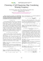
(a)(b)(a)(c)(d)(1) (2) (3)Fig. 6. Attractors and phase differences. ε = 1.35, α = 0.95, ω = 1.50and δ = 0.80. Phase difference of rectangular wave: (a) 0, (b) π/20, (c) π/4and (d) π. (1) x 1 versus y 1 . (2) x 2 versus y 2 . (3) y 1 versus y 2 .Fig. 7(b), subcircuits 1 and 2 are synchronized at oppositephase,subcircuits 2 and 3 are synchronized at opposite-phase.Furthermore, as time passes subcircuits 1 and 3 are synchronizedat opposite-phase, subcircuits 2 and 3 are synchronizedat opposite-phase (see Fig. 7(c)). When the subcircuit parametersare regarded as constant, switching speed is related tothe coupling parameter δ. If the coupling parameter δ is small,bonding force is weak. So switching speed is fast. As the couplingparameter δ increases, switching speed becomes slow.Additionally, self-switching phenomenon of synchronizationsis also confirmed when isolated subcircuits generate periodicattractors for ε = 1.35. However, when the parameter ε issmall, self-switching phenomenon of synchronizations is notobserved. A pair of subcircuits are synchronized at oppositephasethat are decided <strong>by</strong> initial values. Thus, generation ofthe self-switching phenomenon of synchronizations is relatedto the parameter ε, and its switching speed is related to thecoupling parameter δ. By comparison of attractors generatedfrom the isolated subcircuit, local amplitude of the attractorfor ε = 1.5 is larger than it for ε =1.0. We believe that thegeneration of the self-swiching phenomenon is related to thischange of the local amplitude.Second, we consi<strong>der</strong> the case that there is phase differenceof the rectangular wave. Fix ε = 1.50, α = 0.95, ω = 1.50and δ = 0.30, and shift phases of the rectangular wave ofthe subcircuits to 2π/3 and 4π/3. In this case, self-switching(b)(c)Fig. 7. Attractors and phase differences. ε = 1.50, α = 0.95, ω = 1.50and δ = 0.80.phenomenon of synchronizations is not observed. Figure 8shows that three different types of synchronization states.These three synchronization states can be obtained <strong>by</strong> givingdifferent pattern of phase shift of the rectangular wave. Two ofthe three subcircuits are synchronized at the opposite-phase.A pair of synchronized subcircuits is decided <strong>by</strong> the sequenceof phase shift of the rectangular wave.V. CONCLUSIONSIn this study, we investigated synchronization of parametricallyexcited <strong>van</strong><strong>der</strong> <strong>Pol</strong> oscillators. By carrying outcomputer calculations for two or three subcircuits case, weconfirmed that various kinds of synchronization phenomenaof chaos were observed. In the case of two subcircuits, we- 48 -
confirmed that synchronization phenomena are related to phasedifference of the functions that corresponding to the parametricexcitation. Then the two subcircuits are synchronizedat the opposite-phase. In the case of three subcircuits, justthree coupling <strong>van</strong> <strong>der</strong> <strong>Pol</strong> oscillators are synchronized atthe three-phase. However, three coupling parametric excited<strong>van</strong> <strong>der</strong> <strong>Pol</strong> oscillators generate self-switching phenomenonof synchronization states when there is not phase differenceof the the functions corresponding to the parametric excitation.On the other hand, when there is phase difference, two of thethree subcircuits are synchronized at the opposite-phase.ACKNOWLEDGMENTThis work was partly supported <strong>by</strong> Yazaki Memorial Foundationfor Science and Technology.REFERENCES(a)[1] C. Hayashi, “Nonlinear Oscillations in Physical Systems,” Chap. 11,McGraw-Hill, New York (1964).[2] C. Hayashi, M. Abe, K. Oshima and H. Kawakami, “The method ofmapping as applied to the solution for certain types of nonlinear differentialequations,” Ninth International Conference on Nonlinear Oscillations,Kiev (Aug.-Sept.1981).[3] M. Inoue, “A Method of Analysis for the Bifurcation of the Almost PeriodicOscillation and the Generation of Chaos in a Parametric ExcitationCircuit,” Trans. of IEICE, vol. J68-A, no. 7, pp. 621-626, 1985.(b)(c)Fig. 8. Attractors, phase differences and time series. ε = 1.50, α = 0.95,ω = 1.50 and δ = 0.30. Phase differences of rectangular wave are 2π/3 and4π/3.- 49 -