In-Phase and Anti-Phase Synchronization of Switching Phenomena ...
In-Phase and Anti-Phase Synchronization of Switching Phenomena ...
In-Phase and Anti-Phase Synchronization of Switching Phenomena ...

You also want an ePaper? Increase the reach of your titles
YUMPU automatically turns print PDFs into web optimized ePapers that Google loves.
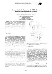
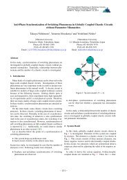
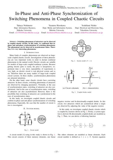
2010 IEEE Workshop onNonlinear Circuit Networks, Tokushima, Dec 3-4, 2010<strong>In</strong>-<strong>Phase</strong> <strong>and</strong> <strong>Anti</strong>-<strong>Phase</strong> <strong>Synchronization</strong> <strong>of</strong><strong>Switching</strong> <strong>Phenomena</strong> in Coupled Chaotic CircuitsTakuya NishimotoDept. <strong>In</strong>formation Business,Shikoku UniversityEmail: s2137034@edu.shikoku-u.ac.jpYasuteru HosokawaDept. Media <strong>and</strong> <strong>In</strong>formation System,Shikoku UniversityEmail: hosokawa@keiei.shikoku-u.ac.jpYoshifumi NishioDept. Electrical <strong>and</strong> Electronic Eng.,Tokushima UniversityEmail: nishio@ee.tokushima-u.ac.jpAbstract— <strong>Switching</strong> phenomena <strong>of</strong> attractors can be observedin coupled chaotic circuits. <strong>In</strong> this study, we confirmed that inphase<strong>and</strong> anti-phase synchronizations <strong>of</strong> switching phenomena.The phenomena can be observed in asynchronous states. Therefore,it is very interesting phenomena.I. INTRODUCTIONMany kinds <strong>of</strong> complex phenomena are observed on largescalecoupled chaotic circuits. <strong>In</strong>vestigations <strong>of</strong> these phenomenaare very important works in order to declare nonlinearphenomena in the natural world. Electric circuits are suitablefor models <strong>of</strong> large-scale coupled nonlinear systems. Becausegetting electric parts is easily, the price is inexpensive, experimenttime is very short, repeatability <strong>of</strong> experiments isvery high, an electric circuit is real physical system <strong>and</strong> soon. Therefore there are many studies <strong>of</strong> large-scale coupledcircuit systems. <strong>In</strong> these studies, synchronization phenomenaare attracted attentions.On the other h<strong>and</strong>, some chaotic circuits have coexistingattractors. <strong>In</strong> these circuits, switching phenomena <strong>of</strong> attractorsare observed by changing parameters. Normally, in the case<strong>of</strong> synchronization states, switching <strong>of</strong> attractors are also synchronized.And in the case <strong>of</strong> asynchrization states, switching<strong>of</strong> attractors are also asynchronized. However, there is thepossibility that switching <strong>of</strong> attractors are synchronized in thecase <strong>of</strong> asynchrization states.<strong>In</strong> this study, we investigate coupled chaotic circuits <strong>and</strong>confirm in-phase <strong>and</strong> anti-phase synchronizations <strong>of</strong> switchingphenomena. Especially, the case that the number <strong>of</strong> circuit istwo is investigated.L1r nin1II. SYSTEM MODELCivnn2L2nCCn(a) Circuit schematicFig. 2. System model (N = 4)Fig. 3.f( id)V-Vrd(b)v-i characteristicsCoupled diodes modelnegative resistor <strong>and</strong> bi-directionally-coupled diodes. <strong>In</strong> thiscircuit, two attractors which are symmetrical about a originare observed by adjusting the value <strong>of</strong> the negative resistor.<strong>In</strong> this study, we investigate coupled chaotic circuits whichis coupled by resistors shown in Fig. 2. Firstly, a system equationis derived. Bi-directionally-coupled diodes are modeled asFig. 3. Then, we can derive a following function(∣ ∣∣∣v d = i d + V ∣ ∣∣∣ −r d∣ i d − V ∣)∣∣∣. (1)r didFig. 1.Circuit modelA circuit model [1] using in this study is shown in Fig. 1.This circuit consists <strong>of</strong> three memory elements, one linearThe others elements are modeled as linear elements. Eachcircuit number is defined as 1 ≤ n ≤ N. System equation- 15 -
TABLE ICOLOR DEFINITION OF FIG. 13 AND FIG. 14.Fig.Fig. 5Fig. 6Fig. 7Fig. 8Fig. 9Fig. 10Fig. 11Fig. 12StateRedGreenBlueLight blueGrayPinkLight greenYellow(a)(b)<strong>of</strong> switching phenomena are only observed. The area is around0.55 ≤ δ ≤ 0.63 <strong>and</strong> 0.46 ≤ α 2 ≤ 0.48. Namely, anti-phasesynchronization is not observed in the case <strong>of</strong> α 1 ≃ α 2 ora small value <strong>of</strong> coupling factor δ. <strong>In</strong> yellow areas as shownin Fig. 14, by decreasing α 2 , synchronization time becomeslong.IV. CONCLUSIONS<strong>In</strong> this study, we have investigated coupled chaotic circuits<strong>and</strong> have observed in-phase <strong>and</strong> anti-phase synchronizations <strong>of</strong>switching phenomena. <strong>In</strong> the case that the number <strong>of</strong> circuitis two, the relationship between parameters <strong>and</strong> phenomena isshown.REFERENCES[1] Y. Nishio, N. <strong>In</strong>aba, S. Mori <strong>and</strong> T. Saito, “Rigorous Analyses <strong>of</strong> Windowsin a Symmetric Circuit,” IEEE Trans. Circuit <strong>and</strong> Systems., vol. 37, no. 4,pp. 473–487, 1990.[2] T. Nishimoto, Y. Hosokawa <strong>and</strong> Y.Nishio, “<strong>Anti</strong>-phase <strong>Synchronization</strong> <strong>of</strong><strong>Switching</strong> <strong>Phenomena</strong> in Globally Coupled System <strong>of</strong> Chaotic Circuits,”IEICE Technical Report, pp. 1–4, 2010.[3] H. Sekiya, S. Mori <strong>and</strong> I. Sasase, “<strong>Synchronization</strong> <strong>of</strong> Self-<strong>Switching</strong><strong>Phenomena</strong> on Full-Coupled Chaotic Oscillators,” IEICE Trans., vol. J83-A, no. 11, pp. 1264–1275, 2000.[4] T. Yamada, Y. Hosokawa <strong>and</strong> Y. Nishio, “Quasi <strong>Synchronization</strong> <strong>Phenomena</strong>in Coupled Chaotic Systems as a Ladder,” Proc. <strong>of</strong> IEEE <strong>In</strong>ternationalWorkshop on Nonlinear Circuit Networks, pp. 68-71, 2008.Fig. 5. <strong>Anti</strong>-phase synchronization <strong>of</strong> switching phenomena. α n = 0.40,β 1 = 3.0, β 2 = 4.5, γ = 470.0 <strong>and</strong> δ = 0.31.(a)(b)Fig. 6. <strong>In</strong>-phase synchronization <strong>of</strong> switching phenomena. α n = 0.40,β 1 = 3.0, β 2 = 15.0, γ = 470.0 <strong>and</strong> δ = 0.33.(a)(b)Fig. 7. Asynchronization <strong>of</strong> switching phenomena. α n = 0.40, β 1 = 3.0,β 2 = 9.0, γ = 470.0 <strong>and</strong> δ = 0.10.Fig. 4. Coexisting attractors <strong>of</strong> a chaotic circuit as shown in Fig. 1. α 1 =0.40, β 1 = 3.0 <strong>and</strong> γ = 470.0.(a)(b)Fig. 8. <strong>Switching</strong> phenomena on one circuit only. α n = 0.40, β 1 = 3.0,β 2 = 12.0, γ = 470.0 <strong>and</strong> δ = 0.10.- 17 -
0.4δ(a)0.3(b)Fig. 9. Holding one attractor state in each circuit. α n = 0.40, β 1 = 3.0,β 2 = 7.5, γ = 470.0 <strong>and</strong> δ = 0.25.0.20.1(a)(b)03 6 9 12 15 18 21β2Fig. 10. Boundary area between Fig. 5 <strong>and</strong> Fig. 7. α n = 0.40, β 1 = 3.0,β 2 = 6.0, γ = 470.0 <strong>and</strong> δ = 0.22.Fig. 13. Relationship among parameter β 2 , δ <strong>and</strong> observed phenomena.α n = 0.40, β 1 = 3.0 <strong>and</strong> γ = 470.0.(a)0.7δ(b)0.6Fig. 11. Boundary area between Fig. 6 <strong>and</strong> Fig. 7. α n = 0.40, β 1 = 3.0,β 2 = 18.0, γ = 470.0 <strong>and</strong> δ = 0.21.0.50.4(a)(b)0.3α20.4 0.42 0.44 0.46 0.48Fig. 12. <strong>Anti</strong>-phase synchronization <strong>of</strong> switching phenomena with synchronizationphenomena. α 1 = 0.40, α 2 = 0.46, β n = 3.0, γ = 470.0 <strong>and</strong>δ = 0.52.Fig. 14. Relationship among parameter α 2 , δ <strong>and</strong> observed phenomena.α 1 = 0.40, β n = 3.0 <strong>and</strong> γ = 470.0.- 18 -