CG-1280 Rev. N 09/13 - General Dynamics SATCOM Technologies
CG-1280 Rev. N 09/13 - General Dynamics SATCOM Technologies
CG-1280 Rev. N 09/13 - General Dynamics SATCOM Technologies
- No tags were found...

You also want an ePaper? Increase the reach of your titles
YUMPU automatically turns print PDFs into web optimized ePapers that Google loves.
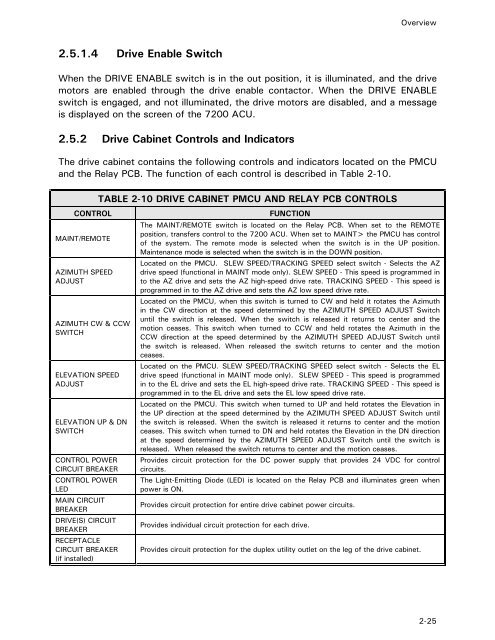
Overview2.5.1.4 Drive Enable SwitchWhen the DRIVE ENABLE switch is in the out position, it is illuminated, and the drivemotors are enabled through the drive enable contactor. When the DRIVE ENABLEswitch is engaged, and not illuminated, the drive motors are disabled, and a messageis displayed on the screen of the 7200 ACU.2.5.2 Drive Cabinet Controls and IndicatorsThe drive cabinet contains the following controls and indicators located on the PMCUand the Relay PCB. The function of each control is described in Table 2-10.CONTROLMAINT/REMOTEAZIMUTH SPEEDADJUSTAZIMUTH CW & CCWSWITCHELEVATION SPEEDADJUSTELEVATION UP & DNSWITCHCONTROL POWERCIRCUIT BREAKERCONTROL POWERLEDMAIN CIRCUITBREAKERDRIVE(S) CIRCUITBREAKERRECEPTACLECIRCUIT BREAKER(if installed)TABLE 2-10 DRIVE CABINET PMCU AND RELAY PCB CONTROLSFUNCTIONThe MAINT/REMOTE switch is located on the Relay PCB. When set to the REMOTEposition, transfers control to the 7200 ACU. When set to MAINT> the PMCU has controlof the system. The remote mode is selected when the switch is in the UP position.Maintenance mode is selected when the switch is in the DOWN position.Located on the PMCU. SLEW SPEED/TRACKING SPEED select switch - Selects the AZdrive speed (functional in MAINT mode only). SLEW SPEED - This speed is programmed into the AZ drive and sets the AZ high-speed drive rate. TRACKING SPEED - This speed isprogrammed in to the AZ drive and sets the AZ low speed drive rate.Located on the PMCU, when this switch is turned to CW and held it rotates the Azimuthin the CW direction at the speed determined by the AZIMUTH SPEED ADJUST Switchuntil the switch is released. When the switch is released it returns to center and themotion ceases. This switch when turned to CCW and held rotates the Azimuth in theCCW direction at the speed determined by the AZIMUTH SPEED ADJUST Switch untilthe switch is released. When released the switch returns to center and the motionceases.Located on the PMCU. SLEW SPEED/TRACKING SPEED select switch - Selects the ELdrive speed (functional in MAINT mode only). SLEW SPEED - This speed is programmedin to the EL drive and sets the EL high-speed drive rate. TRACKING SPEED - This speed isprogrammed in to the EL drive and sets the EL low speed drive rate.Located on the PMCU. This switch when turned to UP and held rotates the Elevation inthe UP direction at the speed determined by the AZIMUTH SPEED ADJUST Switch untilthe switch is released. When the switch is released it returns to center and the motionceases. This switch when turned to DN and held rotates the Elevation in the DN directionat the speed determined by the AZIMUTH SPEED ADJUST Switch until the switch isreleased. When released the switch returns to center and the motion ceases.Provides circuit protection for the DC power supply that provides 24 VDC for controlcircuits.The Light-Emitting Diode (LED) is located on the Relay PCB and illuminates green whenpower is ON.Provides circuit protection for entire drive cabinet power circuits.Provides individual circuit protection for each drive.Provides circuit protection for the duplex utility outlet on the leg of the drive cabinet.2-25