DATA SHEET SERIAL_LCDGT Controller for Graphic LCD with ...
DATA SHEET SERIAL_LCDGT Controller for Graphic LCD with ...
DATA SHEET SERIAL_LCDGT Controller for Graphic LCD with ...
- No tags were found...

Create successful ePaper yourself
Turn your PDF publications into a flip-book with our unique Google optimized e-Paper software.
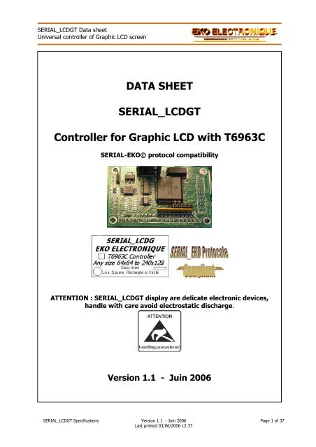
<strong>SERIAL</strong>_<strong><strong>LCD</strong>GT</strong> Data sheetUniversal controller of <strong>Graphic</strong> <strong>LCD</strong> screen<strong>DATA</strong> <strong>SHEET</strong><strong>SERIAL</strong>_<strong><strong>LCD</strong>GT</strong><strong>Controller</strong> <strong>for</strong> <strong>Graphic</strong> <strong>LCD</strong> <strong>with</strong> T6963C<strong>SERIAL</strong>-EKO© protocol compatibilityATTENTION : <strong>SERIAL</strong>_<strong><strong>LCD</strong>GT</strong> display are delicate electronic devices,handle <strong>with</strong> care avoid electrostatic discharge.Version 1.1 - Juin 2006<strong>SERIAL</strong>_<strong><strong>LCD</strong>GT</strong> Specifications Version 1.1 - Juin 2006 Page 1 of 37Last printed 03/06/2006 12:37
<strong>SERIAL</strong>_<strong><strong>LCD</strong>GT</strong> Data sheetUniversal controller of <strong>Graphic</strong> <strong>LCD</strong> screenTABLE OF CONTENTS1 <strong>SERIAL</strong>_<strong><strong>LCD</strong>GT</strong> Pin-out Description .................................................................................... 71.1 JP1 and JP8 Connectors : Communication - Power................................................................. 71.2 JP5 Connector : Back light................................................................................................... 81.3 JP3, JP4 and JP9 Connector : <strong>LCD</strong>........................................................................................ 81.4 Contrast of the <strong>LCD</strong> ............................................................................................................ 91.5 JP7 Connector : Touch Screen / Keyboard –TS OPTION ......................................................... 92 <strong>SERIAL</strong>_<strong><strong>LCD</strong>GT</strong> Configuration / Communications............................................................. 102.1 Selection of the serial connection type SW(2:1) :................................................................ 102.2 Speed selection of the RS232 – TTL asynchronous serial connection SW(4:3) : ...................... 102.3 Selection of the ADRM module address SW(8:5) : ............................................................... 112.4 <strong>SERIAL</strong>_<strong><strong>LCD</strong>GT</strong> wiring and Communications........................................................................ 113 TEXT and GRAPHIC Screens .............................................................................................. 123.1 TEXT Screen .................................................................................................................... 133.2 GRAPHIC Screen............................................................................................................... 143.2.1 ICONS Management.................................................................................................. 143.2.2 <strong>Graphic</strong> FONTS Management ..................................................................................... 144 Available options ...............................................................................................................154.1 –ME Option ...................................................................................................................... 154.2 –TS Option....................................................................................................................... 165 Instructions ....................................................................................................................... 175.1 Global Instructions Set ( $00 - $3F )................................................................................... 175.1.1 $00 : Reading Version register ................................................................................... 175.1.2 $01 : "SET MODE" register Management..................................................................... 175.1.3 $02 : « DISPLAY MODE » register Management .......................................................... 185.1.4 $03 : Writing Back light and Contrast register.............................................................. 185.1.5 $04 : Writing SRAM or EEPROM register ..................................................................... 185.1.6 $05 : Reading SRAM or EEPROM register .................................................................... 195.1.7 $3F : « CONFIG_S<strong>LCD</strong>G » register Management.......................................................... 195.1.8 Summary of registers:............................................................................................... 205.2 Text Instructions set ( $40 - $7F )...................................................................................... 215.2.1 $40 : Erasing TEXTE screen....................................................................................... 215.2.2 $41 : Positioning Cursor at X/Y .................................................................................. 215.2.3 $42 : Cursor management ......................................................................................... 215.2.4 $43 : Display Character ............................................................................................. 225.2.5 $44 : Display Character at X/Y position..................................................................... 225.2.6 $45 : Display ASCII Character.................................................................................... 225.2.7 $46 : Display ASCII Character at X/Y position.............................................................. 225.2.8 $47 : Display ASCII Character string........................................................................... 235.2.9 $50 : Character Description ....................................................................................... 235.2.10 $51 : Character Description and Immediate display ..................................................... 245.2.11 $55 : Erase N Character(s) ........................................................................................ 245.2.12 $56 : Erase a line...................................................................................................... 245.2.13 $60 : Copy TEXTE screen into EEPROM –ME OPTION................................................... 245.2.14 $61 : Load TEXT screen from EEPROM to SRAM – ME OPTION ..................................... 255.2.15 $65 : Set ATTRIBUT_TEXT ........................................................................................ 255.2.16 $7F : PTR_ECRAN_TEXT pointer Management............................................................. 255.3 <strong>Graphic</strong>al Instructions set ( $80 - $AF ) .............................................................................. 265.3.1 $80 : Erase GRAPHIC plan......................................................................................... 265.3.2 $81 : Fill in GRAPHIC plan <strong>with</strong> pattern....................................................................... 265.3.3 $83 : Draw DOT ....................................................................................................... 265.3.4 $84 : Draw Continuation of dots................................................................................. 265.3.5 $85 : Draw LINE....................................................................................................... 275.3.6 $86 : Draw RECTANGLE by two opposite points........................................................... 27<strong>SERIAL</strong>_<strong><strong>LCD</strong>GT</strong> Specifications Version 1.1 - Juin 2006 Page 3 of 37Last printed 03/06/2006 12:37
<strong>SERIAL</strong>_<strong><strong>LCD</strong>GT</strong> Data sheetUniversal controller of <strong>Graphic</strong> <strong>LCD</strong> screenDOCUMENT REVISION HISTORYParagraphs Rev. Date Modifications1.01.101.04.0503.06.06Creation of the document.Correction on pinout tablesNOTA : all the pages carry the index corresponding to their edition even if their contents were notmodified.<strong>SERIAL</strong>_<strong><strong>LCD</strong>GT</strong> Specifications Version 1.1 - Juin 2006 Page 6 of 37Last printed 03/06/2006 12:37
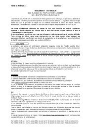
<strong>SERIAL</strong>_<strong><strong>LCD</strong>GT</strong> Data sheetUniversal controller of <strong>Graphic</strong> <strong>LCD</strong> screen1 <strong>SERIAL</strong>_<strong><strong>LCD</strong>GT</strong> Pin-out DescriptionBacklight JP5Communications JP1 - JP8Contrast JP10J2 J3 J4Option -MEOption -TSSW1J1The board is not protected against reverses polarities or high voltage.CAUTION: DO NOT REVERSE POLARITY! This will damage the board.1.1 JP1 and JP8 Connectors : Communication - PowerNom JP1 Pin Type SW1(2:1) DescriptionRX_RS232 4 Input 00 RS232 – SET JUMPER J1RX_TTL 5 Input 00 TTL – REMOVE JUMPER J1SCL 2 InputSDA 3 IO01 I2CGND 6 Ground GNDVCC 1 Power VCC : +5V +-5%Nom JP8 Pin Type SW1(2:1) DescriptionTX_RS232 4 Output 00 TX RS232 to next RX_RS232 moduleTX_TTL 5 Output 00 TX TTL to next RX_TTL moduleNC 2NC 3GND 6 Ground GNDVCC 1 Power VCC : +5V +-5%The mode defined by the SW1(2:1) switches determines the JP1 and JP8 pins to be used. The non usedpins must remain off-line.In the RS232 / TTL mode, the JP8 connector make it possible to easily chain several modules <strong>for</strong> a networkconfiguration. If the TTL mode is used, it is necessary to remove the J1 rider welding.In the I2C mode, all the modules are connected in parallel via the JP1 connector.The <strong>SERIAL</strong>_<strong><strong>LCD</strong>GT</strong> module require only one +5VDC power supply. The current varies according to thenecessary current of the <strong>LCD</strong> back light. ( ATTENTION : can reach 950mA <strong>for</strong> a 240x128 ).<strong>SERIAL</strong>_<strong><strong>LCD</strong>GT</strong> Specifications Version 1.1 - Juin 2006 Page 7 of 37Last printed 03/06/2006 12:37
<strong>SERIAL</strong>_<strong><strong>LCD</strong>GT</strong> Data sheetUniversal controller of <strong>Graphic</strong> <strong>LCD</strong> screen1.2 JP5 Connector : Back lightNom JP5 Pin Type FonctionPWM_BACK 1 Power LED Backlight A ( 1000mA max. / 3 watts max. ) + ResistorGND 2 Ground LED Backlight KNote that a power resistor should be use to limit the current in LED backlight displays. Use the Ohm law tocalculate it. For most LED backlight, use a 2Ohm 3 watts resistor to drop +5V down to+4.1V.S<strong><strong>LCD</strong>GT</strong>JP5.1JP5.22R 3WAK<strong>LCD</strong> screen1.3 JP3, JP4 and JP9 Connector : <strong>LCD</strong>There is a multitude of wirings <strong>for</strong> the connectors of the <strong>LCD</strong>. The S<strong><strong>LCD</strong>GT</strong> provides 3 connectors coveringthe majority of wirings of the <strong>LCD</strong> of the market. The 3 connectors can be assembled on the 2 sides of theS<strong><strong>LCD</strong>GT</strong> PCB. However, all cannot be included. Please check if one of the prints is directly compatible <strong>with</strong>your <strong>LCD</strong>. If not, a manual wiring will have to be carried out to connect the S<strong><strong>LCD</strong>GT</strong> to the <strong>LCD</strong>.Nom Pin JP3 Pin JP4 Pin JP9 Type FonctionGND 1 1, 2 1, 2 Power Ground+VCC 2 3 3 Power Power supply <strong>for</strong> display logicVo 3 4 4 Output V Contrast Control to <strong>LCD</strong>C/D 4 8 8 Output Command / Data select/RD 5 6 6 Output Read/WR 6 5 5 Output WriteD0 à D7 7 – 14 10 - 17 11 - 18 I/O <strong>DATA</strong> bus line 0 to 7/CS 15 7 7 O Chip Select = Chip Enable/RST_<strong>LCD</strong> 16 9 10 O Reset <strong>LCD</strong> screenVee_<strong>LCD</strong> 17 I Operating voltage from <strong>LCD</strong> : -20Vdc MAXMD2 18 O To +5VFS1 19 18 19 O To GND20 NCBelow a non exhaustive table of <strong>LCD</strong> display directly compatible <strong>with</strong> the S<strong><strong>LCD</strong>GT</strong> :JP3 JP4 JP9 <strong>LCD</strong> Taille FabriquantX PG240128-A 240x128 POWERTIPX PG12864-F 128x64 POWERTIPX MGLS-12864T 128x64 VARITRONIXX DMF50316 240x64 OPTREXX DMF50773 240x128 OPTREXX DMF5005 240x64 OPTREXX DMF5001 160x128 OPTREXX PG128128-A 128x128 POWERTIPX PG160128-A 160x128 POWERTIPX PG24064-E 240x64 POWERTIP<strong>SERIAL</strong>_<strong><strong>LCD</strong>GT</strong> Specifications Version 1.1 - Juin 2006 Page 8 of 37Last printed 03/06/2006 12:37
<strong>SERIAL</strong>_<strong><strong>LCD</strong>GT</strong> Data sheetUniversal controller of <strong>Graphic</strong> <strong>LCD</strong> screen1.4 Contrast of the <strong>LCD</strong>The contrast of the <strong>LCD</strong> is regulated by the negative tension Vo of the <strong>LCD</strong> connector.This tension is controlled by the register CONTRASTS:CONTRASTVo$00 0$FF-VeeSome <strong>LCD</strong> are equipped <strong>with</strong> one « Built-in Negative Voltage Generator ».• If this tension is available on the <strong>LCD</strong>, it will be connected to the S<strong><strong>LCD</strong>GT</strong> via the pinVee ( = Vee_<strong>LCD</strong> of the <strong>LCD</strong> connector ).• If this tension is not available on the LC, it can come- maybe from S<strong><strong>LCD</strong>GT</strong> ( -10V = Vee_MAX, usable <strong>for</strong> a screen size lower than 240x60 )- maybe from outside ( -20 volts maximum = Vee_EXT, via JP10 ).The J2, J3 and J4 welding riders make it possible to make the selection of the source of tension, Vcont,used to generate Vo.JxJ2J3J4VcontVee_EXTVee_MAXVee_<strong>LCD</strong>1.5 JP7 Connector : Touch Screen / Keyboard –TS OPTIONJP5 Name Pin Type FonctionKB0 1 I/O Keyboard line 0 / Touch screen line 0KB1 2 I/O Keyboard line 1 / Touch screen line 1KB2 3 I/O Keyboard line 2 / Touch screen line 2KB3 4 I/O Keyboard line 3 / Touch screen line 3KB4 5 I/O Keyboard line 4 / Touch screen line 4This connector requires the – TS option.<strong>SERIAL</strong>_<strong><strong>LCD</strong>GT</strong> Specifications Version 1.1 - Juin 2006 Page 9 of 37Last printed 03/06/2006 12:37
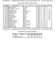
<strong>SERIAL</strong>_<strong><strong>LCD</strong>GT</strong> Data sheetUniversal controller of <strong>Graphic</strong> <strong>LCD</strong> screen2.3 Selection of the ADRM module address SW(8:5) :SW1 (8 :5 ) Address0000 Address 0.. …1111 Address 15ADRM address is obtained by filling out the following table:ADRM1 1 0 SW1(8) SW1(7) SW1(6) SW1(5) R/-W** : The LSB has a significance only in mode I2C. In the othermodes, it is fixed at 0.The photo on the right provides an example of SW1 switches position.SW1 (8 :1)8 7 6 5 4 3 2 11 1 0 0 0 0 0 01 1 0 0 0 0 0 0Mode : 00 RS232 / TTLBaud : 00 2400bpsSW1(8:5) : 1100With the above combination, module’s address is then : ADRM = %11011000 = $D82.4 <strong>SERIAL</strong>_<strong><strong>LCD</strong>GT</strong> wiring and CommunicationsLike all the modules of the <strong>SERIAL</strong>_xxx series, the <strong>SERIAL</strong>_<strong><strong>LCD</strong>GT</strong> modules communicate by the JP1 andJP8 connectors.VccMASTERTX<strong>SERIAL</strong>_<strong>LCD</strong>G 1JP1.4 RSJP1.5 TTLRS JP8.4TTL JP8.5MASTERSCLSDAJP1 3 2SDA SCLRX<strong>SERIAL</strong>_<strong>LCD</strong>G 1Whatever the protocol used, any screen must start <strong>with</strong> a heading. This heading is specific to the selectedcommunications protocol.If the command requires attributes, they are inserted after the heading.Refer to the document "<strong>SERIAL</strong>_EKO Protocol" <strong>for</strong> further in<strong>for</strong>mation’s on thecommunications protocols.<strong>SERIAL</strong>_<strong><strong>LCD</strong>GT</strong> Specifications Version 1.1 - Juin 2006 Page 11 of 37Last printed 03/06/2006 12:37
<strong>SERIAL</strong>_<strong><strong>LCD</strong>GT</strong> Data sheetUniversal controller of <strong>Graphic</strong> <strong>LCD</strong> screen3 TEXT and GRAPHIC ScreensThe <strong>LCD</strong> screen compatible <strong>with</strong> the S<strong><strong>LCD</strong>GT</strong> must integrate a controller of the T6963C type. This lastmanage a SRAM memory of 64 Ko maximum. Just like the T6963C, it is integrated into the <strong>LCD</strong> and itcontains the data to be displayed.All the data safeguarded in a SRAM zone, are lost in absence of power supply.This memory is divided into 3 zones: the zone(s) of TEXTE screen(s), the zone(s) of GRAPHIC screen(s)and the TEXT Font zone.The variables « text_home », « graph_home » and « cgram_home » determine the beginning of the zonesinto SRAM ( see « CONFIG_S<strong><strong>LCD</strong>GT</strong> » register ).According to the size of the SRAM, it is possible to define several TEXT screens and/or several GRAPHscreens in definite SRAM zones.The S<strong><strong>LCD</strong>GT</strong> manage 2 address pointers who determine the beginning of the TEXT and GRAPH screensdisplayed on the <strong>LCD</strong> : « PTR_ECRAN_TEXT » and « PTR_ECRAN_GRAPH ». By modifying these pointers, itis possible to switch from a screen to another.The 2 TEXT and GRAPH screens can be independently lit, extinguished or be combined.The TEXT screen is addressable by characters while the GRAPHIC screen is addressable pixel by pixel.CGRAM Zone : Its size is fixed at 256 * 8 bytes = $0800.TEXT Screen Zone : Its size is a multiple of NBRE_CAR x NBRE_LIGNE.GRAPH Screen Zone : Its size is a multiple of NBRE_PIXELH x NBRE_PIXELV.The « cgram_home » zone beginobligatorily at a multiple address of$0800 :SRAM <strong>LCD</strong> Size Up to 8Ko Up to 32Ko Up to 64KoCgram_homepossible$0000 – $07FF$0800 – $0FFF$1000 – $17FF$0000 – $07FF$0800 – $0FFF$1000 – $17FF...$E000 – $E7FF$E800 – $EFFF$0000 – $07FF$0800 – $0FFF$1000 – $17FF...$E000 – $E7FF$E800 – $EFFF$F000 – $F7FF$F800 – $FFFFThe screens displayed on the <strong>LCD</strong> depend on the value of "PTR_ECRAN_TEXT" and "PTR_ECRAN_GRAPH"pointers.SRAM<strong>LCD</strong>8Ko$2000text_home = $0000$0000zone plan TEXT$077F40x16=x0280 bytescgram_home = $0800graph_home = $1000$1000zone plan GRAPH$1EFF240x128=x0F00 bytes$0000$0280$0500$0780$0800$0900$1000$1F00freefreefree$027F$04FF$077F$07FF$08FF$0FFF$1EFF$1FFFECRANT(0)ECRANT(1)ECRANT(2)CGRAMECRANG(0)<strong>LCD</strong> 240x128avec 8Ko SRAMTo display on the <strong>LCD</strong> the TEXT(1) screencontents in SRAM, PTR_ECRAN_TEXT mustbe set <strong>with</strong> $0280The zone from $0800 to $08FF is reserved<strong>for</strong> the redefined TEXT characters (CGRAM).To display on the <strong>LCD</strong> the GRAPHIC(0)screen contents in SRAM,PTR_ECRAN_GRAPH must be set <strong>with</strong> $1000<strong>SERIAL</strong>_<strong><strong>LCD</strong>GT</strong> Specifications Version 1.1 - Juin 2006 Page 12 of 37Last printed 03/06/2006 12:37
<strong>SERIAL</strong>_<strong><strong>LCD</strong>GT</strong> Data sheetUniversal controller of <strong>Graphic</strong> <strong>LCD</strong> screen3.1 TEXT ScreenA text screen consists of ASCII characters. They can come from the internal ASCII table of the T6963Ccontroller or from a table of characters created by the user. What under hears that even on the TEXTscreen, the screen can manage a minimum of graphs (in the <strong>for</strong>m of redefined characters).The size of the text screen is defined by the following parameters:• NBRE_PIXELH : 0
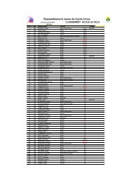
<strong>SERIAL</strong>_<strong><strong>LCD</strong>GT</strong> Data sheetUniversal controller of <strong>Graphic</strong> <strong>LCD</strong> screen3.2 GRAPHIC ScreenThese screens consist of pixels. The maximum definition that the <strong>SERIAL</strong>_<strong><strong>LCD</strong>GT</strong> can manage is 240x128pixels (limitation of the T6963C in « SINGLE-SCREEN » mode). The S<strong><strong>LCD</strong>GT</strong> can manage all the inferiorsizes.A graphic screen is made up of images directly provided to the S<strong><strong>LCD</strong>GT</strong>, or of graphs drawn by the S<strong><strong>LCD</strong>GT</strong>according to commands received from the MASTER.The S<strong><strong>LCD</strong>GT</strong> allows in addition to manage graphical Fonts and Icons.3.2.1 ICONS ManagementThe S<strong><strong>LCD</strong>GT</strong> makes it possible to manage 4 <strong>for</strong>mats of icons : 8x8, 8x16, 16x8 et 16x16 pixels. These iconscan be displayed at any co-ordinates by specifying their higher left corners.The icons are available only if the EEPROM option (– ME OPTION ) is wired on the S<strong><strong>LCD</strong>GT</strong>.Type 0 : 8x8Type 2 : 16x8Type 1 : 8x16Type 3 : 16x163.2.2 <strong>Graphic</strong> FONTS ManagementThe S<strong><strong>LCD</strong>GT</strong> makes it possible to manage graphic fonts. A character of the graphic font consists of 8x8pixels. These characters support the x2, x3 and x4 ZOOM function and can be displayed at any co-ordinatesby specifying their higher left corners.A font can comprise up to 256 characters of 8x8 pixels. Several font can be declared into EEPROM.The graphic fonts are available only if the EEPROM option (- ME OPTION ) is wired on the S<strong><strong>LCD</strong>GT</strong>.<strong>SERIAL</strong>_<strong><strong>LCD</strong>GT</strong> Specifications Version 1.1 - Juin 2006 Page 14 of 37Last printed 03/06/2006 12:37
<strong>SERIAL</strong>_<strong><strong>LCD</strong>GT</strong> Data sheetUniversal controller of <strong>Graphic</strong> <strong>LCD</strong> screen4 Available options4.1 –ME OptionNoted functions -ME OPTION are available only if the EEPROM memory option ( - ME OPTION ) is phisicalywired on the S<strong><strong>LCD</strong>GT</strong>.All the data safeguarded in a EEPROM zone, are preserved even in absence of power supply.The user decides how many TEXT screens, GRAPH screens, icons and graphic font it wishes to memorize<strong>with</strong> the – ME OPTION. It decides the organization of EEPROM memory.The size of the zones to reserve in EEPROM depends on the size of <strong>LCD</strong> screen :Unit size240x64Unit size128x128Unit size240x128RemarksTEXT Screen320bytes 256 bytes 640 bytes Double if TEXT_ATTRIBUT mode40x8 16x16 40x16GRAPHIC Screen1920bytes 2048bytes 3840bytes240x64/8 128x128/8 240x128/8Icon 8x8 ( type 0 ) 8 bytes 8 bytes 8 bytesIcon 8x16 ( type 1 ) 16 bytes 16 bytes 16 bytesIcon 16x8 ( type 2 ) 16 bytes 16 bytes 16 bytesIcon 16x16 ( type 3 ) 32 bytes 32 bytes 32 bytesFont 8x8 8 bytes 8 bytes 8 bytes Many graphical fonts possibleExample 1 : Let us suppose to use 1 <strong>LCD</strong> screen of 240x128 pixels and the S<strong><strong>LCD</strong>GT</strong> <strong>with</strong> the – ME option.The configuration of the TEXT plan is of 40 X 16 characters.DesiredTotal Address EEPROM area -MENameconfigurationsize EEPROM – ME$00001 TEXTE Screen( TEXT_ATTRIBUT OFF )ECRANT(0) $0280 $0000 - $027FECRANG(0) $0F00 $0280 - $117F6 GRAPHIC screen ECRANG(1..4) $3C00 $1180 - $4D7FECRANG(5) $0F00 $4D80 - $5C7F64 icons 8x8 ( type 0 ) ICONE0(0..63) $0200 $5C80 - $5E7F64 icons 16x16 ( type 3 ) ICONE3(0..63) $0800 $5E80 - $667F1 graphical font of128 charactersFONTE0(0..127) $0400 $6680 - $6A7F1 graphical font of64 charactersFONTE1(0..63) $0200 $6A80 - $6C7FFREE $6C80 - $7FFF32Ko256Kb$8000$0280$1180$4D80$5C80$5E80$6680$6A80$6C80$027F$117F$4D7F$5C7F$5E7F$667F$6A7F$6C7FECRANT(0)ECRANG(0)ECRANG(1..4)ECRANG(5)ICONE0(0..63)ICONE3(0..63)FONTE0(0..127)FONTE1(0..64)free$7FFFExample 2 : Let us suppose to use 1 <strong>LCD</strong> screen of 128x128 pixels and the S<strong><strong>LCD</strong>GT</strong> <strong>with</strong> the – ME option.The configuration of the TEXT plan is of 16 X 16 characters.Desired configurationNameTotal Address EEPROM – MEsize BEGINNING – END1 TEXTE screen ( TEXT_ATTRIBUT ON ) ECRANT(0) $0200 $0000 - $01FFECRANG(0) $0800 $0200 - $09FF2 GRAPHIC screen ECRANG(1) $0800 $0A00- $11FF64 icons 8x8 ( type 0 ) ICONE0(0..63) $0200 $1200- $139F16 icons 16x8 ( type 2 ) ICONE2(0..15) $0100 $1400- $14FF1 graphical font of 128 characters FONTE0(0..127) $0400 $1500- $18FFFREE$1900 - $7FFFAll addresses at the beginning of the EEPROM zone must be amultiple of 64 ( $40 ).<strong>SERIAL</strong>_<strong><strong>LCD</strong>GT</strong> Specifications Version 1.1 - Juin 2006 Page 15 of 37Last printed 03/06/2006 12:37
<strong>SERIAL</strong>_<strong><strong>LCD</strong>GT</strong> Data sheetUniversal controller of <strong>Graphic</strong> <strong>LCD</strong> screen4.2 –TS OptionNoted functions - TS OPTION are available only if TOUCH SCREEN option (- TS option) is wired on theS<strong><strong>LCD</strong>GT</strong>.<strong>SERIAL</strong>_<strong><strong>LCD</strong>GT</strong> Specifications Version 1.1 - Juin 2006 Page 16 of 37Last printed 03/06/2006 12:37
<strong>SERIAL</strong>_<strong><strong>LCD</strong>GT</strong> Data sheetUniversal controller of <strong>Graphic</strong> <strong>LCD</strong> screen5 InstructionsAll the functions require an execution time during which the S<strong><strong>LCD</strong>GT</strong> is unavailable. This time depends onthe size of the task to realize (To trace a circle of radius of 10 pixels is faster than one of radius of 50pixels) and of the <strong>LCD</strong> size(More faster to delete a 64 x 64 <strong>LCD</strong> dot than a 240 x 128 <strong>LCD</strong> dot).5.1 Global Instructions Set ( $00 - $3F )5.1.1 $00 : Reading Version registerCommand$00Reading the version number of the software.Remarks :- The response time at a reading request is skeletal (see command $3F: "CONFIG_S<strong>LCD</strong>G").- When the I2C mode is selected, after the reading command "ADRM, $00" it is necessary tomake a reading at the address "ADRM + 1" to obtain the data.User Note :5.1.2 $01 : "SET MODE" register ManagementCommand Attribut1$01 NThis command makes it possible to define the operating mode desired between the TEXT plans andGRAPHIC plans as well as the mode of use of the characters generator ( CG mode ).The T6963C can operate according 2 display modes :• TEXTE mode and/or GRAPHIC mode :The two plans can be combined following the logical manners: AND, OR or EXOR.The plans can be managed in an independent way.• TEXT_ATTRIBUT mode : This mode is a TEXT mode whose each character can have differentspecificities of display. To memorize the display characteristics of each character, the T6963 usesthe GRAPHIC plan. This last is then not available any more <strong>for</strong> the user.By default, at power up, the<strong>SERIAL</strong>_<strong><strong>LCD</strong>GT</strong> initialises theMODE_SET register <strong>with</strong> $80:• OR mode• Internal CGROM• TEXT_ATTRIBUTE OFFSET modeATTENTION : The selection of theTEXT_ATTRIBUTE mode( bit D2 )activate and erases the GRAPHICplan automatically.User Note :GRAPHIC PlanTEXT PlanOR mode$80Internal CG modeAttribut11 0 0 0 D3 D2 D1 D0AND mode$83Internal CG modeLogical DisplayTEXT_ATTRIBUTE DisplayCG selectionEXOR mode$81Internal CG mode00 : OR01 : EXOR11 : AND0 : Off 1 : On0 : Internal 1 : External<strong>SERIAL</strong>_<strong><strong>LCD</strong>GT</strong> Specifications Version 1.1 - Juin 2006 Page 17 of 37Last printed 03/06/2006 12:37
<strong>SERIAL</strong>_<strong><strong>LCD</strong>GT</strong> Data sheetUniversal controller of <strong>Graphic</strong> <strong>LCD</strong> screen5.1.3 $02 : « DISPLAY MODE » register ManagementCommand Attribut1$02 NThis command makes it possible to light or extinguish the TEXT and GRAPH plans and also configuring thedisplay of the TEXT plan cursor.Attribut1By default, at power up, the <strong>SERIAL</strong>_<strong><strong>LCD</strong>GT</strong> initializesDISPLAY_MODE <strong>with</strong> $9C ( TEXT & GRAPHIC ON ).ATTENTION : If the TEXT_ATTRIBUTE mode (bit D2 ofthe "MODE_SET" register) is active, the GRAPHICAL plan is obligatorily activated, but unusable “in terms”GRAPHIC plane. It is requisitioned by the T6963C controller <strong>for</strong> the TEXT plan attributes management.User Note :1 0 0 1 D3 D2 D1 D0Cursor BlinkCursor DisplayTEXT DisplayGRAPHIC Displayon:1 off:0on:1 off:0on:1 off:0on:1 off:05.1.4 $03 : Writing Back light and Contrast registerCommand Attribut1$03 DMemorize in EEPROM the value of the Back light and Contrast.The values are coded on 4 bits. There are thus 16 possibilities <strong>for</strong> contrast and 16 <strong>for</strong> Backlight.• The four-bit MSB corresponds to the CONTRAST.• The four-bit LSB corresponds to the Backlight.These values are stored in a EEPROM zone and recalled at each starting of the board.A pause of 10mS is necessary be<strong>for</strong>e sending the following commands.User Note :5.1.5 $04 : Writing SRAM or EEPROM registerCommand Attribut1 Attribut2$04 A DWriting of the data D to address A. The bit 7 of address A determines whether it is a writing in EEPROM orSRAM:Bit7 Bits(6:0) Description0 ( SRAM ) $00…$7F Writing in SRAM1 ( EEPROM ) $00…$7F Writing in EEPROMThe SRAM zone is initialized <strong>with</strong> 00h at each power up.The EEPROM zone is preserved at the time of the power supply cut-offs. A writing in EEPROM requires10ms be<strong>for</strong>e being carried out.User Note :<strong>SERIAL</strong>_<strong><strong>LCD</strong>GT</strong> Specifications Version 1.1 - Juin 2006 Page 18 of 37Last printed 03/06/2006 12:37
<strong>SERIAL</strong>_<strong><strong>LCD</strong>GT</strong> Data sheetUniversal controller of <strong>Graphic</strong> <strong>LCD</strong> screen5.1.6 $05 : Reading SRAM or EEPROM registerCommand Attribut1$05 AReading <strong>with</strong> address A. The bit 7 of address A determines whether it is a writing in EEPROM or SRAM :Bit7 Bits(6:0) Description0 ( SRAM ) $00…$7F Writing in SRAM1 ( EEPROM ) $00…$7F Writing in EEPROMRemarks :- At starting, the board initializes all the SRAM <strong>with</strong> the 00h value.- The response time at the reading request is skeletal (see command $3F: "CONFIG_S<strong>LCD</strong>G").- When the I2C mode is selected, after the reading command "ADRM, $0E, A" it is necessary tomake a reading <strong>with</strong> the address "ADRM + 1" to obtain the data.- It is not possible to make readings in continuous shooting mode. At a reading commandcorresponds only one reading of data.User Note :5.1.7 $3F : « CONFIG_S<strong>LCD</strong>G » register ManagementCommand CRC1 Attribut1 Attribut2 Attribut3 Attribut4 Attribut5$3F $55 H V Free / Futur O R$F0 $80 $00 $50 $05Attribut6 Attribut7 Attribut8 Attribut9 Attribut10 Attribut11 Attribut12MSB text_home LSB text_home MSB graph_home LSB graph_home MSB CGRAM LSB CGRAM Free / Futur$08 $00 $10 $00 $00 00 $00Attribut13 Attribut14 Attribut15 CRC2Free / Futur Free / Futur Free / Futur $AA$00 $00 $00This command makes it possible to configure the S<strong><strong>LCD</strong>GT</strong> <strong>for</strong> the display whom it must control.ATTENTION :- To make safe the transaction, this screen requires to position values $55 and $$AA inplaces of named attributes CRC1 and CRC2. If the CRC are not correct, the command isignored.- If these values really do not correspond to the type of display used, the operation of theS<strong><strong>LCD</strong>GT</strong> can be erroneous.- 4 attributes are reserved <strong>for</strong> futures extensions.Following the execution of the command, the display displays "REBOOT S<strong><strong>LCD</strong>GT</strong>"It is necessary to reinitialize the <strong>SERIAL</strong>_<strong><strong>LCD</strong>GT</strong> module and the <strong>LCD</strong> in order to take intoaccount the new data.For this, a RESET hardware ( OFF/ON of the <strong>SERIAL</strong>_<strong><strong>LCD</strong>GT</strong> + <strong>LCD</strong> ) is necessary.<strong>SERIAL</strong>_<strong><strong>LCD</strong>GT</strong> Specifications Version 1.1 - Juin 2006 Page 19 of 37Last printed 03/06/2006 12:37
<strong>SERIAL</strong>_<strong>LCD</strong>G Data sheetUniversal controller of <strong>Graphic</strong> <strong>LCD</strong> screenAt delivery of the S<strong><strong>LCD</strong>GT</strong>, the default values of the registers are :AllowedAttributeDescriptionValuesDefaultvalueVariable Name1 H the HORIZONTAL number of pixels $00 - $F0 $F0 ( 240 ) NBRE_PIXELH2 V the VERTICAL number of pixels $00 à $80 $80 ( 128 ) NBRE_PIXELV3 Free / Future4 O Time out <strong>for</strong> the RS232 / TTL mode $00 à $FF $50 ( 8.0mS ) O x 100µs5 RLatency be<strong>for</strong>e emission of the response to thecommand $0E <strong>for</strong> RS232/TTL mode$00 à $FF $05 (0.5mS) R x 100µs6 MSB MSB text_home According to SRAM $087 LSB LSB text_home According to SRAM $00text_home8 MSB MSB graph_home According to SRAM $109 LSB LSB graph_home According to SRAM $00graph_home10 MSB MSB cgram_home According to SRAM $0011 LSB LSB cgram_home According to SRAM $00cgram_home12 Free / Future $0013 Free / Future $0014 Free / Future $0015 Free / Future $00This configuration is correct <strong>for</strong> a POWERTIP PG240128-A <strong>LCD</strong> display : 240 x 128 pixels / 8Ko SRAMTime out weaves reception « O » : 8mSTime be<strong>for</strong>e response « R » = 0.5mSTEXTE font zone : $0000 - $07FF 2048 bytes <strong>for</strong> 256 characters maximum ( 256 x 8 ).TEXTE plane zone : $0800 - $0FFF 2048 bytes <strong>for</strong> 3 TEXTE screens maximum ( 640 x 3 ).GRAPHIC plane zone : $1000 - $1FFF 4096 bytes <strong>for</strong> 1 GRAPHIC screen maximum ( 3840 x 1 ).5.1.8 Summary of registers:Command Function Access Allowed Values Default values$00 Reading S<strong><strong>LCD</strong>GT</strong> VERSION R$01 Writing MODE_SET register W $80 à $8F $80$02 Writing DISPLAY_MODE register W $90 à $9F $9C$03 Writing BACKLIGHT & CONTRAST register W $00 à $FF$04 Writing SRAM or EEPROM memory register W $00 à $FF$05 Reading SRAM or EEPROM memory register R $00 ( SRAM )$20 Pointer indicating the beginning of TEXT plan W According to size SRAM $0800$21 Pointer indicating the beginning of GRAPHIC plan W According to size SRAM $1000$3F Writing CONFIG_S<strong>LCD</strong>G register W<strong>SERIAL</strong>_<strong>LCD</strong>G Specifications Version 1.1 - Juin 2006 Page 20 of 37Last printed 03/06/2006 12:37
<strong>SERIAL</strong>_<strong>LCD</strong>G Data sheetUniversal controller of <strong>Graphic</strong> <strong>LCD</strong> screen5.2 Text Instructions set ( $40 - $7F )The TEXTE screen must be activated ( bit D2 of the « DISPLAY_MODE » register ) <strong>for</strong> the followingfunctions. All the commands operate on the TEXT screen during display. The “PTR_ECRAN_TEXT” pointerdefines the TEXT screen displayed.5.2.1 $40 : Erasing TEXTE screenCommand$40Erase the contents of the text screen and position the cursor at the beginning of first line (high left on thescreen, position 0,0).User Note :5.2.2 $41 : Positioning Cursor at X/YCommand Attribut1 Attribut2$41 X YPlace the cursor in position X ( 0 to Nbre_CAR-1 characters ) and Y ( 0 to Nbre_LIGNE-1 lines ) .Nbre_CAR and Nbre_LIGNE being the number of characters and thenumber of lines of the <strong>LCD</strong> display.Exemple :Attribut1 = $02Attribut2 = $05Place the cursor in third position on the sixth line.Remarks :- At lighting, the S<strong>LCD</strong>G places the cursor on top, on the left of the first line (0, 0).- An incoherent value X or Y compared to the <strong>LCD</strong> type describes by the "CONFIG_S<strong>LCD</strong>G"function does not cause any change.- See the command $3F : “ CONFIG_S<strong>LCD</strong>G “.User Note :005.2.3 $42 : Cursor managementCommand Attribut1$42 NWhen TEXT screen is lit and as well the CURSOR( « DISPLAY_MODE » register ), this command definesthe thickness of the used cursor: from 1 to 8 pixels.CURSOR PATTERN modeBy default, at lighting, the S<strong>LCD</strong>G initializes the cursor<strong>with</strong> size $01 but does not activate it.1
<strong>SERIAL</strong>_<strong>LCD</strong>G Data sheetUniversal controller of <strong>Graphic</strong> <strong>LCD</strong> screen5.2.4 $43 : Display CharacterCommand Attribut1$43 NDisplay the N character, at the current cursor position.The bit D3 of the “MODE_SET” register defines the text font used.ATTENTION : When D3 = ‘0’ ( « MODE_SET » register ), the T6963C integrates an offset of $20 in its ASCIItable. To post the "0" character, the attribut1 should be sent: N = $30 - $20 = $10.MODE_SETAttribut1DescriptionBit D3User Note :$00 à $7F Display of one of the 128 characters of the <strong>LCD</strong> ROM0 ( Internal CGROM )Display of one of the first 128 characters of the <strong>LCD</strong> RAM$80 à $FF(redefined characters)1 ( External CGRAM ) $00 à $FF Display of one of the 256 characters of the <strong>LCD</strong> RAM5.2.5 $44 : Display Character at X/Y positionCommand Attribut1 Attribut2 Attribut3$44 X Y NSame command that the preceding one, but positions the cursor at (X,Y) co-ordinates be<strong>for</strong>e displaying theN character. If the co-ordinates are invalid, the command is ignored.The bit D3 of the “MODE_SET” register defines the text font used.User Note :5.2.6 $45 : Display ASCII CharacterCommand Attribut1$45 NDisplay the N character, at the current cursor position.The bit D3 of the “MODE_SET” register defines the text font used.User Note :5.2.7 $46 : Display ASCII Character at X/Y positionCommand Attribut1 Attribut2 Attribut3$46 X Y NSame command that the preceding one, but positions the cursor at (X,Y) co-ordinates be<strong>for</strong>e displaying theN character. If the co-ordinates are invalid, the command is ignored.The bit D3 of the “MODE_SET” register defines the text font used.User Note :<strong>SERIAL</strong>_<strong>LCD</strong>G Specifications Version 1.1 - Juin 2006 Page 22 of 37Last printed 03/06/2006 12:37
<strong>SERIAL</strong>_<strong>LCD</strong>G Data sheetUniversal controller of <strong>Graphic</strong> <strong>LCD</strong> screen5.2.8 $47 : Display ASCII Character stringData transmissionCommand Attribut1BURST mode$47 NDisplay a string of N characters, at the current cursor position.The characters are sent according to the following transfer protocol :Data Transmission BURST modeData0 … Data62PAUSE 1mSLAST <strong>DATA</strong> ?To send 64 bytes of data.- Pauses of 1mS after each 64 bytes.- The sequence is finished after reception of theN bytes (255 maximum).- The last burst access can be lower than 64bytes.ATTENTION : When this command is started on at least 1 S<strong><strong>LCD</strong>GT</strong> module, it should be finished be<strong>for</strong>emaking <strong>for</strong>ward of another type of commands. According to the size of the screen, it is necessary to leavetime to the <strong>LCD</strong> to display it be<strong>for</strong>e sending another command.User Note :5.2.9 $50 : Character DescriptionCommand Attribut1 Attribut2 Attribut3 … Attribut9$50 N C1 C2 … C8This command redefines the character number N (from $00 to $$FF) in the <strong>LCD</strong> RAM.The C1 to C8 attributes are the 8 bytes that describe the character. See the paragraph of the creation ofthe symbols <strong>for</strong> more details on coding of these attributes.According to the state of the CG_ROM bit ( « MODE_SET » register ), the S<strong><strong>LCD</strong>GT</strong> authorizes theredefinition of 128 or 256 characters maximum :• D3 = ‘0’ 128 ( from $80 to FF ) redefinable characters• D3 = ‘1’ 256 ( from $00 to FF ) redefinable charactersMODE_SET - Bit D30 ( Internal CGROM )Attribut1$00 à $7F 128 non-redefinable characters$80 à $FF 128 redefinable characters1 ( External CGRAM ) $00 à $FF 256 redefinable charactersThe position of the cursor in the TEXT plan is unchanged.ATTENTION :- ALL N characters displayed on the TEXT plan at validation time of the order will bemodified.- If the « Internal CGROM » mode is selected, the definition of a character lower than $80is <strong>with</strong>out effect.User Note :<strong>SERIAL</strong>_<strong>LCD</strong>G Specifications Version 1.1 - Juin 2006 Page 23 of 37Last printed 03/06/2006 12:37
<strong>SERIAL</strong>_<strong>LCD</strong>G Data sheetUniversal controller of <strong>Graphic</strong> <strong>LCD</strong> screen5.2.10 $51 : Character Description and Immediate displayCommand Attribut1 Attribut2 Attribut3 … Attribut9$51 N C1 C2 … C8Identical to the preceding function but displays in more immediately the redefined character, at the currentcursor position. This last is then shifted of one position on the right or passes to the line if it were at theend of the line.MODE_SET - Bit D3Attribut1 : NUser Note :0 ( Internal CGROM ) $80 à $FF 128 redefinable characters1 ( External CGRAM ) $00 à $FF 256 redefinable characters5.2.11 $55 : Erase N Character(s)Command Attribut1$55 NErase N character at the left of the cursor of the TEXT plan.User Note :5.2.12 $56 : Erase a lineCommand Attribut1$4A NErase line N and positions the cursor at the beginning of this line.0
<strong>SERIAL</strong>_<strong>LCD</strong>G Data sheetUniversal controller of <strong>Graphic</strong> <strong>LCD</strong> screen5.2.14 $61 : Load TEXT screen from EEPROM to SRAM – ME OPTIONCommand Attribut1 Attribut2 Attribut3 Attribut4$61 MSB_EEP LSB_EEP MSB_SRAM LSB_SRAMThis function places the screen pointed in EEPROM, by attributes 1 & 2 in the TEXT plan.If TEXT_ATTRIBUT mode is activated, the characteristics are also restored.This function is available only if the EEPROM memory option (-ME option) is wired on the S<strong>LCD</strong>G.ATTRIBUT 1 & 2 : MSB and LSB address corresponding to the beginning of EEPROM zone reserved to thisplan (multiple of $40).ATTRIBUT 3 & 4 : MSB and LSB address corresponding to the beginning of SRAM zone reserved to thisscreen.If PTR_ECRAN_TEXT is different from attributes MSB & LSB SRAM, the screen is not displayed. It is justplaced in SRAM and accessible by moving the PTR_ECRAN_TEXT pointer.The text cursor is positioned at the (0,0) co-ordinates.User Note :5.2.15 $65 : Set ATTRIBUT_TEXTCommand Attribut1 Attribut2$65 S NThis function determines the display mode of the characters when the TEXT_ATTRIBUT mode is selected. Itmakes it possible to affect the style of display "S", at N consecutive characters of the TEXT screen actuallydisplayed.It is necessary to position the text cursor (Command $41) be<strong>for</strong>e carrying out this function.Attribute SStyleXXXX 0 0 0 0 Normal displayXXXX 0 1 0 1 Reverse displayXXXX 0 0 1 1 Inhibit displayXXXX 1 0 0 0 Blink of normal displayXXXX 1 1 0 1 Blink of reverse displayXXXX 1 0 1 1 Blink of inhibit displayATTENTION : - The use of the TEXT_ATTRIBUT mode prevents from using the GRAPHIC plan.- This function is usable only if the TEXT_ATTRIBUT mode is validated ("MODE_SET"register).User Note :5.2.16 $7F : PTR_ECRAN_TEXT pointer ManagementCommand Attribut1 Attribut2$7F MSB_PTR_TEXT LSB_PTR_TEXTDefined the beginning of the TEXT screen displayed on the <strong>LCD</strong>. If several screens are stored consecutivelyin SRAM in the TEXT plan, this function makes it possible to make an effect of vertical scrolling into thezone of TEXT plan or to pass quickly from a screen to another.User Note :<strong>SERIAL</strong>_<strong>LCD</strong>G Specifications Version 1.1 - Juin 2006 Page 25 of 37Last printed 03/06/2006 12:37
<strong>SERIAL</strong>_<strong>LCD</strong>G Data sheetUniversal controller of <strong>Graphic</strong> <strong>LCD</strong> screen5.3 <strong>Graphic</strong>al Instructions set ( $80 - $AF )These functions are usable only if the TEXT_ATTRIBUT mode ("SET_MODE" register) is not used. TheGRAPHIC plan must be activated ( bit D3 of “ DISPLAY_MODE “ ).When no address of SRAM is required, the commands operate on the GRAPHIC screen actually displayed.The “PTR_ECRAN_GRAPH” pointer defines the displayed GRAPHIC screen.On cetain <strong>LCD</strong> screens, a de<strong>for</strong>mation of the figures can occur : a circle will be oval, a square will berectangular. This occurs when the <strong>LCD</strong> screen has nonsquare pixels.5.3.1 $80 : Erase GRAPHIC planCommand$80Entirely erase the GRAPHIC plan <strong>with</strong> OFF pixels.User Note :5.3.2 $81 : Fill in GRAPHIC plan <strong>with</strong> patternCommand Attribut1$81 PatternEntirely filled the GRAPHIC plan <strong>with</strong> the pattern definedby attribute 1.User Note :Pattern = $00Pattern = $55Pattern = $AA5.3.3 $83 : Draw DOTCommand Attribut1 Attribut2$83 X1 Y1Draw a dot of color DOT_COLOR to the co-ordinates (X1, Y1).0
<strong>SERIAL</strong>_<strong>LCD</strong>G Data sheetUniversal controller of <strong>Graphic</strong> <strong>LCD</strong> screenThe co-ordinates of the dots are sent according to the following transfer protocol:Data Transmission BURST modeData0 … Data63PAUSE 1mSLAST <strong>DATA</strong> ?Send 64 bytes of data.- Pause of 1mS after each 64 bytes- The sequence is finished after reception of allthe bytes.- The last burst access can be lower than 64bytes.ATTENTION : When this command is started on at least 1 S<strong><strong>LCD</strong>GT</strong> module, it should be finished be<strong>for</strong>emaking <strong>for</strong>ward another type of command.User Note :5.3.5 $85 : Draw LINECommand Attribut1 Attribut2 Attribut3 Attribut4$85 X1 Y1 X2 Y2Draw a line, of color DOT_COLOR, starting at point of co-ordinates (X1,Y1) to the ending point at co-ordinates (X2, Y2).0
<strong>SERIAL</strong>_<strong>LCD</strong>G Data sheetUniversal controller of <strong>Graphic</strong> <strong>LCD</strong> screen5.3.8 $88 : Draw CERCLECommand Attribut1 Attribut2 Attribut3$88 X1 Y1 RDraw a circle, of color DOT_COLOR, of center (X, Y) and of radius R.0
<strong>SERIAL</strong>_<strong>LCD</strong>G Data sheetUniversal controller of <strong>Graphic</strong> <strong>LCD</strong> screen5.3.12 $8C : Draw SQUARINGCommand Attribut1 Attribut2 Attribut3 Attribut4 Attribut5 Attribut6 Attribut7$8C X1 Y1 X2 Y2 Gx Gy NDraw a squaring, of color DOT_COLOR, whose co-ordinates of thehigher left corner are (X1,Y1) and of the lower right corner are (X2,Y2).Nbre_PIXELHGx and Gy determine the number of pixels between each lines.0
<strong>SERIAL</strong>_<strong>LCD</strong>G Data sheetUniversal controller of <strong>Graphic</strong> <strong>LCD</strong> screen5.3.14 $91 : Load <strong>Graphic</strong> Screen in EEPROM from MASTER - ME OptionCommand Attribut1 Attribut2Data transmission$91 MSB_EEP LSB_EEPBURST modeLoad a screen in a EEPROM zone from the MASTER.ATTRIBUT 1 & 2 : MSB and LSB address corresponding to the beginning of the EEPROM zone reserved <strong>for</strong>this screen (multiple of $40).The S<strong><strong>LCD</strong>GT</strong> waits (NBRE_PIXELH X NBRE_PIXELV) / 8 bytes.The data of the screen are sent according to the following transfer protocol :Data Transmission BURST modeData0 … Data63PAUSE 10mSLAST <strong>DATA</strong> ?Send 64 bytes ones after the others.- Pauses of 10mS after each 64 bytes- The sequence is finished after reception of all thebytes.The last burst access can be lower than 64 bytes.ATTENTION : When this command is engaged on at least 1 S<strong><strong>LCD</strong>GT</strong> module, it should be finished be<strong>for</strong>esending another type of commands.User Note :5.3.15 $92 : Display <strong>Graphic</strong> screen into <strong>LCD</strong> SRAM from EEPROM - ME OptionCommand Attribut1 Attribut2 Attribut3 Attribut4$92 MSB_EEP LSB_EEP MSB_SRAM LSB_SRAMLoad the graphic screen pointed in EEPROM into the pointed SRAM zone of the <strong>LCD</strong>.ATTRIBUT 1 & 2 : MSB and LSB address corresponding to the beginning of the EEPROM zone reserved <strong>for</strong>this screen (multiple of $40).ATTRIBUT 3 & 4 : MSB and LSB address corresponding to the beginning of the SRAM zone reserved <strong>for</strong> thisscreen.User Note :5.3.16 $93 : Copy GRAPHIC screen into EEPROM from <strong>LCD</strong> SRAM – ME OPTIONCommand Attribut1 Attribut2$93 MSB_EEP LSB_EEPCopy the GRAPHIC plan actually displayed in the EEPROM zone pointed by the attributes 1 and 2.This function makes it possible to safeguard the screen actually displayed in EEPROM in order to, <strong>for</strong>example, displaying it again during a <strong>for</strong>thcoming power up. The screen actually displayed is not modified.This function is usable only if the TEXT_ATTRIBUT mode is not used. It only copies the GRAPHIC plan.Attributes 1 and 2 : MSB and LSB addressee corresponding to the beginning of the EEPROM zone reservedat this screen (multiple of $40).User Note :<strong>SERIAL</strong>_<strong>LCD</strong>G Specifications Version 1.1 - April 2006 Page 30 of 37Last printed 03/06/2006 12:37
<strong>SERIAL</strong>_<strong>LCD</strong>G Data sheetUniversal controller of <strong>Graphic</strong> <strong>LCD</strong> screen5.3.17 $95 : Load 8x8 ICON into EEPROM from MASTER – ME OPTIONCommand Attribut1 Attribut2 Attribut3 … Attribut..$95 MSB_EEP LSB_EEP C1 … C85.3.18 $96 : Load 8x16 ICON into EEPROM from MASTER – ME OPTIONCommand Attribut1 Attribut2 Attribut3 … Attribut..$96 MSB_EEP LSB_EEP C1 … C165.3.19 $97 : Load 16x8 ICON into EEPROM from MASTER – ME OPTIONCommand Attribut1 Attribut2 Attribut3 … Attribut..$97 MSB_EEP LSB_EEP C1 … C165.3.20 $98 : Load 16x16 ICON into EEPROM from MASTER – ME OPTIONCommand Attribut1 Attribut2 Attribut3 … Attribut..$98 MSB_EEP LSB_EEP C1 … C32Load the icon in pointed EEPROM zone.The icon is consisted of the C1 to Cn bytes.See the paragraph of descriptions of the icons.TypeDefinitionSizeinto EEPROM - ME0 8x8 8 bytes C1 to C81 8x16 16 bytes C1 to C162 16x8 16 bytes C1 to C163 16x16 32 bytes C1 to C32ATTRIBUT 1 & 2 : MSB and LSB address corresponding to the beginning of the EEPROM zone reserved tothis icon (multiple of $40).ATTRIBUT 3 to .. : Data of the icon ( from 8 to 32 bytes ).User Note :Type 0 : 8x8Type 1 : 8x16Attribut4 = $01Attribut5 = $03Attribut6 = $07...Type 2 : 16x8Type 3 : 16x16Attribut4 = $01Attribut5 = $80Attribut6 = $03Attribut7 = $C0Attribut8 = $07Attribut9 = $E0......5.3.21 $99 : Display ICON – ME OPTIONCommande Attribut1 Attribut2 Attribut3 Attribut4 Attribut5$99 MSB_EEP LSB_EEP TYPE X YDisplay icon of TYPE type, pointed in the EEPROM zone, at (X,Y) position on the GRAPHIC screen.Co-ordinates (X,Y) indicate the higher left corner of the icon.Nbre_PIXELHIf (X,Y) co-ordinates are invalid, the command is ignored:TypeX/Y01230
<strong>SERIAL</strong>_<strong>LCD</strong>G Data sheetUniversal controller of <strong>Graphic</strong> <strong>LCD</strong> screen5.3.22 $9A : Load <strong>Graphic</strong>al FONT into EEPROM from MASTER – ME OPTIONCommand Attribut1 Attribut2 Attribut3 Data transmission$9A MSB_EEP LSB_EEP NBURST modeLoad a graphic font into a zone of the EEPROM from the MASTER.The font consists of N characters. Each character consists of 8 bytes.ATTRIBUT 1 & 2 : MSB and LSB address corresponding to the beginning of the EEPROM zone reserved tothis font (multiple of $40).The data are sent according to the following transfer protocol :Data Transmission BURST modeData0 … Data63PAUSE 10mSLAST <strong>DATA</strong> ?Send 64 bytes ones after the others.- Pauses of 10mS after each 64 bytes- The sequence is finished after reception of all thebytes.The last burst access can be lower than 64 bytes.ATTENTION : When this command is engaged on at least 1 S<strong><strong>LCD</strong>GT</strong> module, it should be finished be<strong>for</strong>esending another type of commands.User Note :5.3.23 $9B : Display graphical Character at X/Y position – ME OPTIONCommand Attribut1 Attribut2 Attribut3 Attribut4 Attribut5 Attribut6$9B MSB_EEP LSB_EEP N C X YDisplay the character N of the graphic font, whose first character is at the address pointed in EEPROMMSB_EEP & LSB_EEP, at (X,Y) position, <strong>with</strong> the zoom in progress, on the GRAPHIC screen actuallydisplaying.The combination <strong>with</strong> the displaying of the graphicscreen in progress is selected by the attribut4 : C.CCombinaison0 OR Add pixels1 AND2 Not AND Take away pixels3 EXOR Invert pixelsThe zoom is selected by the SET_ZOOM_FACTOR function ( $A0 ).(X,Y) co-ordinates indicate the higher left corner of the character. If (X,Y) co-ordinates are invalid, thecommand is ignored :ZOOM_FACTOR = 1 ZOOM_FACTOR = 2 ZOOM_FACTOR = 3 ZOOM_FACTOR = 40
<strong>SERIAL</strong>_<strong>LCD</strong>G Data sheetUniversal controller of <strong>Graphic</strong> <strong>LCD</strong> screen5.3.24 $A0 : Reverse ( video ) GRAPHIC screenCommand$A0Cause a video inversion of all the displayed GRAPHIC screen.User Note :Nbre_PIXELHNbre_PIXELV5.3.25 $A1 Reverse (video) zone of the GRAPHIC screenCommand Attribut1 Attribut2 Attribut3 Attribut4$A1 X1 Y1 X2 Y2Cause a video inversion of the pixels contained in the zone of which the co-ordinates of the higher leftcorner are (X1, Y1) and the corner lower right are (X2,Nbre_PIXELHY2). The inversion operates the GRAPHIC screen.0,00
<strong>SERIAL</strong>_<strong>LCD</strong>G Data sheetUniversal controller of <strong>Graphic</strong> <strong>LCD</strong> screen5.3.28 $BF : PTR_ECRAN_GRAPH pointer managementCommand Attribut1 Attribut2$BF MSB_PTR_GRAPH LSB_PTR_GRAPHPosition the beginning of the GRAPHIC screen displayed on the <strong>LCD</strong>. If several screens are storedconsecutively in SRAM, this function makes it possible to make an effect of vertical scrolling into the zone ofthe GRAPHIC plan.User Note :5.4 TOUCHSCREEN / KEYBOARD instructions set ( $C0 - $CF )5.4.1 $C0 : TOUCHSCREEN / KEYBOARD Reading – TS OPTIONCommand Attribut1$C0 N5.4.2 $C1 : TOUCHSCREEN / KEYBOARD Configuration – TS OPTIONCommand Attribut1 Attribut2 Attribut3 Attribut4$C1 K N X Y<strong>SERIAL</strong>_<strong><strong>LCD</strong>GT</strong> Specifications Version 1.1 - April 2006 Page 34 of 37Last printed 003/06/2006 12:37
<strong>SERIAL</strong>_<strong>LCD</strong>G Data sheetUniversal controller of <strong>Graphic</strong> <strong>LCD</strong> screen6 ASCII Table of T6963CThe T6963C exists <strong>with</strong> 2 possible ASCII tables. The second one ( CGROM Type 0201 ) is <strong>for</strong> the Asiancountries.The characters table of the T6963C integrates an offset of $20 positions, compared to a standard ASCIItable. The character "0", which corresponds to the ASCII code $30, is at address $10 of the T6963C table.Consequently, to display the character "0", it is enough to send the code ($30 - $20) = $10.<strong>SERIAL</strong>_<strong><strong>LCD</strong>GT</strong> Specifications Version 1.1 - April 2006 Page 35 of 37Last printed 003/06/2006 12:37
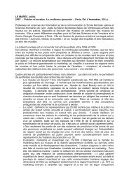
<strong>SERIAL</strong>_<strong>LCD</strong>G Data sheetUniversal controller of <strong>Graphic</strong> <strong>LCD</strong> screen7 Schema<strong>SERIAL</strong>_<strong><strong>LCD</strong>GT</strong> Specifications Version 1.1 - April 2006 Page 36 of 37Last printed 003/06/2006 12:37
<strong>SERIAL</strong>_<strong>LCD</strong>G Data sheetUniversal controller of <strong>Graphic</strong> <strong>LCD</strong> screen8 <strong>SERIAL</strong>_<strong><strong>LCD</strong>GT</strong> Electrical and Mechanical characteristicsMin / Max Unit RemarksSupply voltage 4.5 / 5.5 VSupply current 0.1 / 20 mA ( back light not included)V Backlight 0 / 5 V PWMI Backlight 0 / 1000 mA Consumption of <strong>LCD</strong> back lightV Contraste -20 / 0 V Selection by J2, J3 and J4I Contraste 0 / 1 mACommunication speed 2400 / 76800100 / 400BaudsKHzRS232 or TTL modeI2C modeOperating temperature -10 / +60 °C According to the <strong>LCD</strong>Storage temperature -20 / +80 °C WITHOUT <strong>LCD</strong>Vibrations 0 / 1 g Under operation, in all directions ( Fmax 10Hz )<strong>LCD</strong> fixed by screw + nuts + discs9 <strong>SERIAL</strong>_<strong><strong>LCD</strong>GT</strong> References / Applications NotesMode Description Remarques RéférencesI2C 1 <strong>SERIAL</strong>_<strong><strong>LCD</strong>GT</strong>-ME – 1 DEVBOARD1 ( PIC16F876A ) Full graphical screen demonstrations AN1_S<strong><strong>LCD</strong>GT</strong>.BASTTL 1 <strong>SERIAL</strong>_<strong><strong>LCD</strong>GT</strong>-ME – 1 DEVBOARD1 ( PIC16F876A ) Full graphical screen demonstrations AN2_S<strong><strong>LCD</strong>GT</strong>.BASTTL 1 <strong>SERIAL</strong>_<strong><strong>LCD</strong>GT</strong>-ME – 1 BasicStamp II Full graphical screen demonstrations AN3_S<strong><strong>LCD</strong>GT</strong>.BS2<strong>SERIAL</strong>_<strong><strong>LCD</strong>GT</strong> Specifications Version 1.1 - April 2006 Page 37 of 37Last printed 003/06/2006 12:37