4-BTV, 5-BTV, 6-BTV Multiband HF - K6RF Home of the Porta Base ...
4-BTV, 5-BTV, 6-BTV Multiband HF - K6RF Home of the Porta Base ...
4-BTV, 5-BTV, 6-BTV Multiband HF - K6RF Home of the Porta Base ...

Create successful ePaper yourself
Turn your PDF publications into a flip-book with our unique Google optimized e-Paper software.
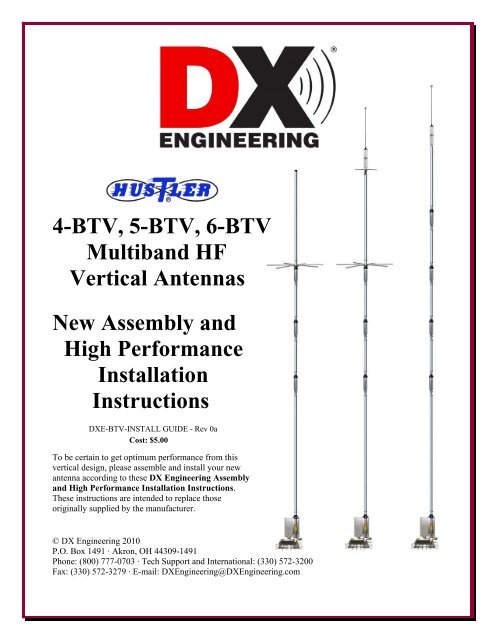
4-<strong>BTV</strong>, 5-<strong>BTV</strong>, 6-<strong>BTV</strong><br />
<strong>Multiband</strong> <strong>HF</strong><br />
Vertical Antennas<br />
New Assembly and<br />
High Performance<br />
Installation<br />
Instructions<br />
DXE-<strong>BTV</strong>-INSTALL GUIDE - Rev 0a<br />
Cost: $5.00<br />
To be certain to get optimum performance from this<br />
vertical design, please assemble and install your new<br />
antenna according to <strong>the</strong>se DX Engineering Assembly<br />
and High Performance Installation Instructions.<br />
These instructions are intended to replace those<br />
originally supplied by <strong>the</strong> manufacturer.<br />
© DX Engineering 2010<br />
P.O. Box 1491 · Akron, OH 44309-1491<br />
Phone: (800) 777-0703 · Tech Support and International: (330) 572-3200<br />
Fax: (330) 572-3279 · E-mail: DXEngineering@DXEngineering.com<br />
- 1 -
Table <strong>of</strong> Contents<br />
Chapter 1 - Introduction<br />
Congratulations ! 4<br />
Over 50 Years Ago 4<br />
Hustler <strong>BTV</strong> antennas 5<br />
You gotta be kidding me...... 6<br />
Basic Assembly and Enhanced Operating Assembly 6<br />
Chapter 2 - General Information<br />
Warning 7<br />
Overhead Power Line Safety 7<br />
Basic Tools Required 7<br />
Assembly Notes 7<br />
Chapter 3 - Common Starting Information<br />
Installation Sequence 8<br />
Site Selection 9<br />
Mounting Pipe 9<br />
Concrete or No Concrete – That is THE Question 10<br />
Coaxial Cable to Mounting Pipe 11<br />
Chapter 4 - Some Really Good Information<br />
Get <strong>the</strong> Best Performance From Your New Quarter-Wave Vertical Antenna 11<br />
Some Brief Words on Ground Mounting, Elevated Mounting, and Radial Wires 12<br />
How to Put Radial Wires Down Without Digging 13<br />
Radial System Considerations 14<br />
Chapter 5 - Basic <strong>BTV</strong> Assembly<br />
Assembling Vertical Aluminum Antenna Sections & Element Clamps 17<br />
Hustler <strong>Base</strong> Assembly 19<br />
Hustler 4 <strong>BTV</strong> - Package Contents & Assembly 20<br />
Hustler 5 <strong>BTV</strong> - Package Contents & Assembly 22<br />
Six Blade Spider for <strong>the</strong> 4-<strong>BTV</strong> and 5-<strong>BTV</strong> only 24<br />
Three Blade Spider for <strong>the</strong> 5-<strong>BTV</strong> only 24<br />
80 Meter Resonator and Whip Installation for <strong>the</strong> 5-<strong>BTV</strong> and 6-<strong>BTV</strong> 24<br />
Hustler 6 <strong>BTV</strong> - Package Contents & Assembly 25<br />
Mating <strong>the</strong> Vertical Sections to <strong>the</strong> <strong>Base</strong> Section 27<br />
Installing Radials & Feedline on <strong>the</strong> Hustler <strong>Base</strong> 28<br />
Coax RF Choke 29<br />
Basic Tuning 29<br />
Chapter 6 - DX Engineering Enhanced Antenna Systems<br />
Special Hustler <strong>BTV</strong> Packages Available from DX Engineering 30<br />
Radial Plate to Mounting Pipe 32<br />
Attaching Ground Radial Wires to <strong>the</strong> Radial Plate 33<br />
Tilt <strong>Base</strong> Mounting Plate to Mounting Pipe 34<br />
<strong>BTV</strong> Antenna <strong>Base</strong> Section to Tilt <strong>Base</strong> 34<br />
Testing <strong>the</strong> Tilt <strong>Base</strong> 35<br />
Alternate Feedpoint Connections 36<br />
The DXE-VFCC-H05-A Vertical Feedline Current Choke 37<br />
- 2 -
Chapter 7 - Tuning<br />
Understanding Trap Calibration 39<br />
Hustler Traps 40<br />
Hustler Trap Calibration - Resonance Adjustment Procedure 42<br />
Tuning <strong>the</strong> 80 Meter Resonator Whip for <strong>the</strong> 5-<strong>BTV</strong> and 6-<strong>BTV</strong> 43<br />
Chapter 8 - Guying <strong>the</strong> Hustler <strong>BTV</strong> Antenna System 44<br />
Chapter 9 - Reference Information<br />
Elevated Mounting <strong>of</strong> <strong>the</strong> Hustler <strong>BTV</strong> Antenna 45<br />
The Quarter-Wave Vertical on a Metal Ro<strong>of</strong> 46<br />
What Trap Do I Have? 48<br />
Hustler <strong>BTV</strong> Replacement Parts Diagram 49<br />
Wea<strong>the</strong>rpro<strong>of</strong>ing Coaxial Cable Connections 05<br />
Lightning Protection - For Any Installation 50<br />
Hustler <strong>BTV</strong> Specifications 51<br />
Chapter 10 - Additional Operating Bands<br />
Adding Additional Operating Bands to your Hustler <strong>BTV</strong> Antenna 54<br />
Chapter 11 - Recommended Accessory Items<br />
For Assembly 55<br />
For Quick Tilt Action 55<br />
For Tuning 56<br />
Additional Accessories for Your Hustler <strong>BTV</strong> 56<br />
Technical Support and Warranty 60<br />
Note: DX Engineering is constantly upgrading information and developing new products to<br />
enhance your amateur radio experience. Please check <strong>the</strong> DX Engineering web site for <strong>the</strong><br />
latest information: www.DXEngineering.com<br />
Manual Updates and Information<br />
Every effort is made to supply <strong>the</strong> latest manual revision with each product. Occasionally a manual<br />
will be updated between <strong>the</strong> time your DX Engineering product is shipped and when you receive it.<br />
Please check <strong>the</strong> DX Engineering web site (www.dxengineering.com) for <strong>the</strong> latest revision manual.<br />
- 3 -
Chapter 1 - Introduction<br />
Congratulations ! 4<br />
50 Years Ago 4<br />
Hustler <strong>BTV</strong> antennas 5<br />
You gotta be kidding me...... 6<br />
Basic Assembly and Enhanced Operating Assembly 6<br />
Congratulations on your purchase <strong>of</strong> one <strong>of</strong> <strong>the</strong> most versatile <strong>HF</strong> multi-band antennas, <strong>the</strong><br />
Hustler <strong>HF</strong> <strong>Base</strong> model 4-<strong>BTV</strong>, 5-<strong>BTV</strong> or 6-<strong>BTV</strong>, or a complete DX Engineering Hustler High<br />
Performance <strong>HF</strong> Vertical System Package: models DXE-HUS-4<strong>BTV</strong>-P, DXE-HUS-5<strong>BTV</strong>-P or<br />
DXE-HUS-6<strong>BTV</strong>-P.<br />
Your new Hustler <strong>HF</strong> antenna system <strong>of</strong>fers automatically selected multi-band coverage with an<br />
omni-directional pattern. The high quality, low-loss traps are adjustable, so you may tune <strong>the</strong><br />
antenna for low SWR and maximum performance in virtually all types <strong>of</strong> installations. The Hustler<br />
<strong>BTV</strong> Series <strong>HF</strong> <strong>Base</strong> Vertical is mechanically and electrically superior to o<strong>the</strong>r brands, and will<br />
<strong>of</strong>fer years <strong>of</strong> top performance. If <strong>the</strong> system is installed with <strong>the</strong> DX Engineering Hustler antenna<br />
options according to <strong>the</strong> recommendations and instructions in this manual, <strong>the</strong> full capabilities <strong>of</strong><br />
this antenna are realized<br />
DX Engineering has worked extensively with <strong>the</strong> Hustler <strong>BTV</strong> series <strong>of</strong> antennas and has custom<br />
manufactured <strong>the</strong> best quality optional items to enhance <strong>the</strong> <strong>HF</strong> operating performance. Using DX<br />
Engineering parts will ensure that your Hustler <strong>BTV</strong> antenna will enable you to achieve an<br />
outstanding presence on <strong>the</strong> amateur bands for years to come.<br />
Over 50 Years Ago!<br />
The Hustler <strong>HF</strong> <strong>Base</strong> Four Band Trap Vertical antenna was a new concept in 1959. This unique multiband<br />
antenna with an exclusive low-loss trap design was developed and introduced to Amateurs by<br />
Hustler, Inc. <strong>of</strong> Cleveland, Ohio, <strong>of</strong>fering quarter-wave antenna performance for 40, 20 15 and 10<br />
meters , but requiring no band switching!<br />
Later, <strong>the</strong> Hustler Four Band Trap Vertical, known around <strong>the</strong> world as <strong>the</strong> 4-<strong>BTV</strong>, was made<br />
available with an 80 meter resonator, and <strong>the</strong> 5-<strong>BTV</strong> was born. When <strong>the</strong> Amateur bands expanded in<br />
1979, <strong>the</strong> last <strong>of</strong> <strong>the</strong> series <strong>of</strong>ferings designed by Hustler, <strong>the</strong> 6-<strong>BTV</strong>, added 30 meters, for an<br />
unequalled vertical antenna. Since 1985 <strong>the</strong> New-Tronics Antenna Corporation in Mineral Wells,<br />
Texas, has been making high quality antennas for <strong>HF</strong>, V<strong>HF</strong> and U<strong>HF</strong> Amateur and Commercial<br />
customers, including <strong>the</strong> “Hustler <strong>BTV</strong> Series”.<br />
Since 2003, DX Engineering has <strong>of</strong>fered Hustler Antennas and has developed a complete system <strong>of</strong><br />
innovative accessories and Add-On Kits specifically for <strong>the</strong> Hustler <strong>BTV</strong> series. Amateurs now have<br />
<strong>the</strong> choice <strong>of</strong> complete Hustler <strong>BTV</strong> Series High Performance packages for <strong>the</strong>ir <strong>HF</strong> needs, including<br />
<strong>the</strong> ability to turn <strong>the</strong>ir Hustler into a “9-<strong>BTV</strong>” covering all bands 80 through 10 meters.<br />
DX Engineering joins New-Tronics Antenna Corporation in celebrating over 50 years <strong>of</strong> service with<br />
<strong>the</strong> famous Hustler <strong>HF</strong> <strong>Base</strong> Four Band Trap Vertical – The Hustler 4-<strong>BTV</strong>.<br />
- 4 -
Hustler <strong>BTV</strong> Antennas<br />
The Hustler 4-<strong>BTV</strong> is a four-band trap vertical antenna<br />
providing an omni directional pattern. The 4-<strong>BTV</strong> is<br />
designed as a self supporting vertical to provide optimum<br />
performance on <strong>the</strong> 10, 15, 20 and 40 meter bands. This<br />
antenna is designed for installations with restricted space.<br />
The Hustler 4-<strong>BTV</strong> is approximately 19 feet tall. It can also<br />
be adapted to operate on <strong>the</strong> 75/80 meter band by adding <strong>the</strong><br />
RM-80S resonator and <strong>the</strong> 4457-1 three blade spider<br />
assembly on top <strong>of</strong> <strong>the</strong> 4-<strong>BTV</strong>. If <strong>the</strong> 75/80 meter resonator<br />
is attached to <strong>the</strong> 4-<strong>BTV</strong>, it may be desirable to guy <strong>the</strong><br />
antenna above <strong>the</strong> 20 meter trap with small diameter<br />
polypropylene rope.<br />
The Hustler 5-<strong>BTV</strong> is a five-band trap vertical antenna. This<br />
antenna includes <strong>the</strong> RM-80S resonator and <strong>the</strong> 4457-1 three<br />
blade spider assembly. The 5-<strong>BTV</strong> is designed to provide<br />
excellent performance on <strong>the</strong> 10, 15, 20, 40 and 75/80 meter<br />
bands. The Hustler 5-<strong>BTV</strong> is approximately 24 feet tall.<br />
The Hustler 6-<strong>BTV</strong> is a six-band trap vertical antenna. The<br />
6-<strong>BTV</strong> is designed to provide excellent performance on <strong>the</strong><br />
10, 15, 20, 30, 40 and 75/80 meter bands, using four traps<br />
and <strong>the</strong> RM-80S resonator. The design <strong>of</strong> <strong>the</strong> 6-<strong>BTV</strong> is sleek,<br />
with no capacity spiders and is approximately 25 feet tall.<br />
The Hustler <strong>BTV</strong> antennas provide automatic electrical<br />
selection <strong>of</strong> <strong>the</strong> bands through <strong>the</strong> use <strong>of</strong> optimum Q traps,<br />
which are individually and precisely tuned at New-Tronics.<br />
The traps are parallel tuned circuits which provide efficient<br />
isolation between <strong>the</strong> vertical sections, permitting multi-band<br />
operation. Efficient operation over <strong>the</strong> many ham bands at<br />
good SWRs is possible in a proper installation.<br />
The Hustler <strong>BTV</strong> antennas were designed to provide optimum performance from both an electrical<br />
and mechanical standpoint. Mechanically, this antenna boasts a heavy duty base and heavy duty<br />
aluminum tubing. The mechanical assembly is accomplished with all stainless steel hardware. The<br />
use <strong>of</strong> clamps permits re-adjustment if necessary, and allows tuning <strong>of</strong> each band. The mechanical<br />
construction is such that guying is not ordinarily needed.<br />
The performance provided by <strong>the</strong> Hustler <strong>BTV</strong> antenna is better than any o<strong>the</strong>r antenna <strong>of</strong> this type.<br />
Broad banding is such that one setting permits both phone and CW operation on most bands. The<br />
antenna provides a nominal 52 Ω base impedance when installed and tuned according to<br />
instructions. The radiation efficiency is equivalent to, or greater than, o<strong>the</strong>r trap verticals.<br />
- 5 -
You gotta be kidding me......<br />
When you first looked at this manual you probably wondered "What is all this?!?!?!" Do I<br />
really need to read all this stuff? Well, this manual was put toge<strong>the</strong>r using many years <strong>of</strong><br />
antenna design experience in making <strong>the</strong> Hustler <strong>BTV</strong> Vertical Antenna perform to <strong>the</strong><br />
utmost. DX Engineering has sold thousands <strong>of</strong> Hustler <strong>BTV</strong>s with DX Engineering add-on<br />
parts that have been engineered, tested and proven to enhance <strong>the</strong> operation <strong>of</strong> <strong>the</strong> Hustler<br />
<strong>BTV</strong> series <strong>of</strong> antennas.<br />
When you install any antenna, you want <strong>the</strong> maximum performance and <strong>the</strong>se instructions<br />
will help you achieve that goal with <strong>the</strong> Hustler <strong>BTV</strong>.<br />
Can you install <strong>the</strong> antenna without all <strong>the</strong>se extra parts? Sure, but your performance will be<br />
far less than optimum.<br />
DX Engineering constantly examines <strong>the</strong> performance <strong>of</strong> <strong>the</strong> Hustler <strong>BTV</strong> series antennas<br />
and continually engineers add-ons to get <strong>the</strong> best possible <strong>HF</strong> performance.<br />
When installed using <strong>the</strong>se instructions and DX Engineering accessories, you will have an<br />
antenna system that will exceed your expectations and provide you with years <strong>of</strong> great<br />
contacts on <strong>the</strong> <strong>HF</strong> Amateur bands!<br />
Basic Assembly and Enhanced Operating Assembly:<br />
We at DX Engineering believe that <strong>the</strong> Hustler <strong>BTV</strong> antenna is great and can be installed quickly to<br />
get you on <strong>the</strong> air making contacts.<br />
Through years <strong>of</strong> experience, DX Engineering has engineered and manufactured add-ons that will<br />
make <strong>the</strong> Hustler <strong>BTV</strong> performance even better!<br />
Do you need <strong>the</strong> high performance options now? No, you can get started with <strong>the</strong> basic system and<br />
add enhancements over time. Many hams that have added DX Engineering <strong>BTV</strong> antenna options<br />
have exclaimed <strong>the</strong> resulting higher performance was like getting a new antenna!<br />
This manual has chapters for:<br />
Basic assembly instructions for those wanting to install a <strong>BTV</strong> right out <strong>of</strong> <strong>the</strong> box with no<br />
performance enhancing options. (Chapter 5)<br />
Assembly using DX Engineering options that have been engineered to obtain maximum<br />
performance from a <strong>BTV</strong> antenna system. (Chapter 6)<br />
You'll want to read all <strong>the</strong> information in order to make an informed decision for your installation.<br />
Proper planning for your installation will provide you with years <strong>of</strong> great operation on <strong>the</strong> <strong>HF</strong> bands<br />
using <strong>the</strong> Hustler <strong>BTV</strong> series antenna. To be certain to get optimum performance from this vertical<br />
design, please assemble and install your new antenna according to <strong>the</strong>se DX Engineering<br />
Assembly and High Performance Installation Instructions. These instructions may be used in<br />
place <strong>of</strong> those originally supplied by <strong>the</strong> manufacturer. The Hustler <strong>BTV</strong> series <strong>of</strong> antennas is<br />
manufactured by New-Tronics Antenna Corporation, Mineral Wells, Texas.<br />
- 6 -
Chapter 2 - General Information<br />
Warning 7<br />
Overhead Power Line Safety 7<br />
Basic Tools Required 7<br />
Assembly Notes 7<br />
WARNING!<br />
INSTALLATION OF ANY ANTENNA NEAR POWER LINES IS DANGEROUS<br />
Warning: Do not locate <strong>the</strong> antenna near overhead power lines or o<strong>the</strong>r electric light or power<br />
circuits, or where it can come into contact with such circuits. When installing <strong>the</strong> antenna, take<br />
extreme care not to come into contact with such circuits, because <strong>the</strong>y may cause serious injury or<br />
death.<br />
Overhead Power Line Safety<br />
Before you begin working, check carefully for overhead power lines in <strong>the</strong> area you will be<br />
working. Don't assume that wires are telephone or cable lines: check with your electric utility for<br />
advice. Although overhead power lines may appear to be insulated, <strong>of</strong>ten <strong>the</strong>se coverings are<br />
intended only to protect metal wires from wea<strong>the</strong>r conditions and may not protect you from electric<br />
shock<br />
Keep your distance! Remember <strong>the</strong> 10-foot rule: When carrying and using ladders and o<strong>the</strong>r long<br />
tools, keep <strong>the</strong>m at least 10 feet away from all overhead lines - including any lines from <strong>the</strong> power<br />
pole to your home.<br />
Basic Tools Required<br />
Two 7/16" open end wrenches or nut drivers<br />
Medium size flat blade screwdriver or 5/16" nut driver for <strong>the</strong> element clamps<br />
Tape measure<br />
Felt-tip marker<br />
Assembly Notes<br />
Note: DXE-P8A Penetrox A Anti-Oxidant should be used between all antenna element<br />
sections. Penetrox is an electrical joint compound to affect a substantial electrical<br />
connection between metal parts such as telescoping aluminum tubing or o<strong>the</strong>r<br />
antenna pieces. It ensures high conductivity at all voltage levels by displacing moisture<br />
and preventing corrosion or oxidation.<br />
Note: DXE-81343 Never-Seez or NSBT8 Anti-Seize should be used on all clamps, bolts and<br />
stainless steel threaded hardware to prevent galling and to ensure proper tightening.<br />
- 7 -
Chapter 3 - Common Starting Information<br />
Installation Sequence 8<br />
Site Selection 9<br />
Mounting Pipe 9<br />
Concrete or no concrete - That is THE question 10<br />
Coaxial Cable to Mounting Pipe 11<br />
Installation Sequence<br />
1. Site Selection 7. Antenna Assembly<br />
2. Installing a Mounting Pipe 8. Mating <strong>the</strong> <strong>BTV</strong> antenna to <strong>the</strong> base section<br />
3. Run Coax from Radio to Mounting Pipe 9. Walk <strong>the</strong> antenna up to normal position<br />
4. Install <strong>the</strong> Radial Plate and Radial System 10. Tuning<br />
5. Install <strong>the</strong> Tilt <strong>Base</strong> Assembly 11. Add optional DX Engineering Add-On Kits<br />
6. Mount <strong>the</strong> <strong>BTV</strong> base to <strong>the</strong> Tilt <strong>Base</strong> for 12, 17 and 60 meters and make adjustments<br />
Site Selection Hole for Mounting Pipe Concrete & Level Trench for Coax<br />
Coax to <strong>Base</strong> Gravel to keep Radial Wires Installed Rocks added for<br />
Install Radial Plate weeds away Antenna Installed good looks<br />
Tilt <strong>Base</strong> & VFCC<br />
Trench Filled Shack end - Ground Rod<br />
and new grass seeded and PolyPhaser protection<br />
K3EMB's Hustler 6-<strong>BTV</strong> installation - Total installation time: 3 days<br />
(your time may vary)<br />
- 8 -<br />
17 Meter Add-On-Kit<br />
Tuned and on <strong>the</strong> air!
Site Selection<br />
• Install your new vertical antenna a minimum <strong>of</strong> 20 feet away from buildings, wires,<br />
metal fences, downspouts and gutters. Centering a vertical antenna in an open area is <strong>the</strong><br />
best option. Installing <strong>the</strong> antenna near a wooden fence or on a wood post is okay as long<br />
as <strong>the</strong>re is no metal within 20 feet <strong>of</strong> <strong>the</strong> antenna.<br />
• Installing <strong>the</strong> antenna on a metal mounting pipe or a wooden post that is set in concrete<br />
is okay. Since <strong>the</strong> radial system wires create <strong>the</strong> efficient ground return for RF currents,<br />
direct earth grounding <strong>of</strong> <strong>the</strong> support post or a ground rod is not required at <strong>the</strong> antenna.<br />
Select a mounting location clear from power lines, structures and o<strong>the</strong>r antennas by a minimum <strong>of</strong><br />
40 feet (30 + 10 ft safety rule). Consider overhead power lines, utility cables and wires. The<br />
fur<strong>the</strong>r away <strong>the</strong> vertical is mounted from local noise sources or o<strong>the</strong>r metallic objects, which can<br />
re-radiate noise and affect <strong>the</strong> tuning, radiation pattern and SWR, <strong>the</strong> better. Determine <strong>the</strong> direction<br />
you want <strong>the</strong> antenna to pivot and make sure <strong>the</strong>re is adequate clearance (at least 30 feet).<br />
Mounting Pipe<br />
The mounting support may be a galvanized metal pipe or thick wall steel tube from 1 inch to 1-3/4<br />
inches outside diameter (OD) when using just <strong>the</strong> Hustler bracket, and 1 inch to 2 inches OD when<br />
using <strong>the</strong> DXE-TB-3P Tilt <strong>Base</strong>. A thick-walled steel pipe with a minimum thickness <strong>of</strong> 1/8" (1/4"<br />
preferred) should be used. The standard 1-1/2" galvanized water<br />
pipe (with its 1.9" OD) is just fine for this application and can<br />
usually be found at your local home building supply store. A 4<br />
to 6 inch wood post can also be used.<br />
Use a thick-walled galvanized steel mounting pipe<br />
approximately 6 feet long. This will allow approximately 4 feet<br />
to be below ground and 20-23 inches above ground.<br />
The height <strong>of</strong> <strong>the</strong> mounting pipe above ground level <strong>of</strong> 20-23<br />
inches will allow you to do ei<strong>the</strong>r a basic installation, or an<br />
enhanced installation by adding <strong>the</strong> DX Engineering optional<br />
items described in this detailed manual. In some cases ham<br />
operators have done a basic installation, and <strong>the</strong>n added <strong>the</strong> DX<br />
Engineering optional items at a later date to enhance <strong>the</strong>ir<br />
operation. Thus, <strong>the</strong> length <strong>of</strong> mounting pipe above ground is 20<br />
to 23 inches.<br />
For permanent mounting, use a post-hole digger to make <strong>the</strong><br />
hole deep enough to accommodate approximately 4 feet <strong>of</strong> pipe<br />
and a couple inches <strong>of</strong> gravel at <strong>the</strong> bottom for drainage. Set <strong>the</strong><br />
pipe on <strong>the</strong> gravel, use <strong>the</strong> pre-mix concrete to fill around <strong>the</strong><br />
pipe, adding water and mixing as you fill (or mix <strong>the</strong> concrete<br />
first, depending on <strong>the</strong> type you purchase), <strong>the</strong>n pour <strong>the</strong><br />
concrete in <strong>the</strong> hole. Fill <strong>the</strong> hole until <strong>the</strong> concrete is level with <strong>the</strong> ground around it. Use a level as<br />
you fill <strong>the</strong> hole to be sure <strong>the</strong> pipe is vertically straight. Allow to set overnight.<br />
- 9 -
Your location, landscape and ground conditions may require different mounting solutions in order<br />
to have <strong>the</strong> steel mounting pipe and <strong>the</strong> vertical antenna in a secure position. You may also attach<br />
<strong>the</strong> Tilt <strong>Base</strong> to a 4 to 6 inch wooden post at <strong>the</strong> location you intend to use <strong>the</strong> antenna, making sure<br />
<strong>the</strong> unit is securely mounted.<br />
Using a cyclone fence is not recommended for a vertical antenna support or being used as a radial<br />
system. Poor RF connections and <strong>the</strong> presence <strong>of</strong> high levels <strong>of</strong> noise that are inherent on metal<br />
fences make <strong>the</strong>m an undesirable mounting location for any <strong>HF</strong> vertical antenna.<br />
Note: Steel, ra<strong>the</strong>r than aluminum, is much more suitable for mounting in concrete. Aluminum<br />
will quickly corrode due to incompatibility with <strong>the</strong> materials used to make concrete.<br />
Concrete or No Concrete – That is THE Question<br />
The original Hustler <strong>BTV</strong> installation manuals call for <strong>the</strong> ground mounting pipe to be driven into<br />
<strong>the</strong> earth with <strong>the</strong> specific wording “Do not use concrete. Do not dig a hole and bury <strong>the</strong> mast. It<br />
must be driven in.” The reason for this recommendation is so that installations with few or no<br />
radials will be able to make use <strong>of</strong> <strong>the</strong> direct contact between <strong>the</strong> mounting pipe and <strong>the</strong> earth to<br />
collect and distribute antenna currents.<br />
Unfortunately, <strong>the</strong> soil and a steel pipe usually does not provide efficient RF conduction. Therefore,<br />
<strong>the</strong> use <strong>of</strong> many ground radial wires are recommended for all quarter-wave ground mounted <strong>HF</strong><br />
antenna, to improve efficiency and performance dramatically.<br />
Also, a driven or pounded pipe may be used on any ground-mounted vertical antenna installation,<br />
regardless <strong>of</strong> <strong>the</strong> number <strong>of</strong> radials used.<br />
DX Engineering recommends using a concrete base, as shown on page 9, when a high performance<br />
installation with many radials is planned. The reasons that a concrete base is recommended:<br />
1. It is easier to make sure that <strong>the</strong> mounting pipe is vertical when it is braced for installation<br />
with concrete. Pounded pipes can develop a lean or hit a rock while being driven into <strong>the</strong><br />
ground, which could result in a leaning antenna.<br />
2. A steel pipe or tube in concrete will last much longer than in soil, especially in certain types<br />
<strong>of</strong> soil that will corrode steel more quickly.<br />
3. Concrete is not an insulator for a steel pipe, as <strong>the</strong> hardened but moist concrete is a good<br />
conductor from <strong>the</strong> steel to <strong>the</strong> soil for grounding purposes.<br />
4. A ground surface wire radial system <strong>of</strong>fers far more efficient means to collect and distribute<br />
surface RF currents than a single pipe in <strong>the</strong> soil, so a pipe in concrete is okay when using<br />
many radials.<br />
- 10 -
Coaxial Cable to Mounting Pipe<br />
The coaxial cable should be routed from your radio room to <strong>the</strong> base<br />
<strong>of</strong> <strong>the</strong> antenna system and be buried below <strong>the</strong> radial system you will<br />
be installing.<br />
PVC Conduit pipe may be used to house <strong>the</strong> coaxial cable. Bury <strong>the</strong><br />
cable 4" to 12" below ground level.<br />
Chapter 4 - Some Really Good Information<br />
Get <strong>the</strong> Best Performance From Your New Quarter-Wave Vertical Antenna 11<br />
Some Brief Words on Ground Mounting, Elevated Mounting, and Radial Wires 12<br />
How to Put Radial Wires Down Without Digging 13<br />
Radial System Considerations 14<br />
Get <strong>the</strong> Best Performance From Your New Quarter-Wave Vertical Antenna<br />
To be certain to get optimum performance from this vertical design, please assemble and install<br />
your new antenna according to <strong>the</strong>se DX Engineering Assembly and High Performance<br />
Installation Instructions. These instructions are intended to replace those originally supplied by<br />
<strong>the</strong> manufacturer. The Hustler <strong>BTV</strong> series <strong>of</strong> antennas is manufactured by New-Tronics Antenna<br />
Corporation, Mineral Wells, Texas.<br />
By following <strong>the</strong>se instructions you will be able to take advantage <strong>of</strong> all <strong>of</strong> <strong>the</strong> performance that<br />
your Hustler <strong>HF</strong> Multi-Band Vertical has to <strong>of</strong>fer. Here are a few facts about <strong>the</strong> <strong>HF</strong> quarter-wave<br />
vertical antenna:<br />
• For best results, plan for a ground-mount installation with many radials. Engineers and<br />
Amateurs “in-<strong>the</strong>-know” install a complete ground radial wire system to significantly<br />
improve quarter-wave vertical antenna performance for transmitting and receiving. Use<br />
copper wire. Do not use grids, mesh fence material or steel which are known to be poor<br />
performers especially for <strong>the</strong> long term.<br />
• Mounting this antenna without radials results in average to below average performance and<br />
only local or medium range contacts. Due to RF ground losses, a vertical installation with no<br />
radials or only a few radials will have drastically reduced efficiency. On those installations,<br />
even though a wider frequency range <strong>of</strong> low SWR may result, that is a very poor trade-<strong>of</strong>f<br />
for an antenna system that <strong>of</strong>fers performance.<br />
- 11 -
• Any <strong>HF</strong> vertical mounted a few to many feet above ground with only a few radials suffers<br />
virtually <strong>the</strong> same ground losses as a ground mounted vertical with a few radials. This<br />
manual shows you how to plan and install ground radials for better antenna performance and<br />
gratifying operational results in almost any situation.<br />
• Height is not a requirement for <strong>HF</strong> Verticals. Unlike horizontally oriented antennas, ground<br />
mounted vertical antennas used for <strong>HF</strong> sky wave communications only require a radial<br />
system for performance. If an <strong>HF</strong> quarter-wave vertical antenna is elevated, <strong>the</strong>n it requires<br />
resonant, quarter wavelength, tuned radials to be efficient and functional. Safer groundmounted<br />
installations can produce results far superior to elevated <strong>HF</strong> verticals with a few<br />
radials.<br />
• For low-angle performance, a horizontal antenna requires height, and if it is directional, may<br />
not be able to be rotated, or it requires a tower and rotator. In comparison, an omnidirectional<br />
<strong>HF</strong> vertical installed with many radials <strong>of</strong>fers an excellent performance-to-cost<br />
value.<br />
Some Brief Words on Ground Mounting, Elevated Mounting, and Radial Wires<br />
Ground Mounting<br />
There are multiple ways to install a Hustler <strong>BTV</strong> antenna. The most efficient way is to ground<br />
mount <strong>the</strong> antenna, keeping clear <strong>of</strong> any metal objects and using a good ground radial system.<br />
Ground mounting your quarter-wave vertical antenna will produce significantly improved long<br />
range results when your installation includes a good ground-level radial wire system. Seven decades<br />
<strong>of</strong> experiments show that ground mounting with many radials is your best choice.<br />
Safety is ano<strong>the</strong>r important consideration when comparing ground mounting to<br />
ro<strong>of</strong>-top or elevated mounting <strong>of</strong> your quarter-wave vertical. The DX<br />
Engineering Tilt <strong>Base</strong> <strong>of</strong>fers a safer and easier ground mounted installation.<br />
One person can walk-up and tilt-down <strong>the</strong> antenna for adjustments without a<br />
ladder. The new, more versatile Tilt <strong>Base</strong> models are also helpful when high<br />
winds are expected. Order <strong>the</strong> Tilt <strong>Base</strong> model DXE-TB-3P for your Hustler<br />
<strong>BTV</strong>.<br />
Elevated Mounting<br />
You may also elevate <strong>the</strong> Hustler <strong>BTV</strong> antenna. However, when elevating <strong>the</strong> antenna <strong>the</strong> radial<br />
system becomes more difficult to deploy in that you need specific length radials that must also be<br />
elevated, running symmetrically away from <strong>the</strong> feedpoint.<br />
In some situations, an elevated or ro<strong>of</strong>-mounted vertical installation is <strong>the</strong> only option. Resonancetuned<br />
radials must do <strong>the</strong> job <strong>of</strong> collecting RF currents. Imagine all <strong>of</strong> <strong>the</strong> quarter-wave resonant<br />
length wires attached to <strong>the</strong> base <strong>of</strong> <strong>the</strong> antenna, spreading radially (away from <strong>the</strong> base <strong>of</strong> <strong>the</strong><br />
vertical in all directions). For best DX performance, <strong>the</strong>se radials should slope down from <strong>the</strong><br />
elevate vertical at a 45 degree angle. You can connect <strong>the</strong> ends <strong>of</strong> <strong>the</strong> long radials to support poles<br />
or trees. Use <strong>the</strong> same care as you would for a dipole antenna, keeping <strong>the</strong> ends insulated and clear<br />
- 12 -
<strong>of</strong> any metal. We recommend four resonant radials per band to enhance low angle radiation. More<br />
information on planning and installing <strong>the</strong> elevated quarter-wave vertical appears later in Chapter 9.<br />
Radial Wires<br />
Radials: Probably THE most important item, for not only <strong>the</strong> Hustler <strong>BTV</strong>, but any ground<br />
mounted quarter-wave vertical antenna system are <strong>the</strong> radial wires. Lack <strong>of</strong> radial wires causes a<br />
serious compromise to performance.<br />
Will <strong>the</strong> antenna work without radial wires? In most cases, yes - BUT - it will work at a much lower<br />
efficiency in both transmit and receive. Some hams who tried <strong>the</strong> 'no radial' method and later added<br />
a good radial system were very surprised in <strong>the</strong> difference it made with enhanced transmit<br />
efficiency and <strong>the</strong> ability to receive many more weak signals. The importance <strong>of</strong> a good radial<br />
system cannot be stressed enough.<br />
Radials are easy to install and <strong>the</strong> following section outlines <strong>the</strong> easiest and most efficient way <strong>of</strong><br />
installing radial wires that will withstand a powered grass mower and provide your antenna with <strong>the</strong><br />
best possible radial system.<br />
How To Put Radial Wires Down Without Digging<br />
The best time to do this is early spring but it can be done o<strong>the</strong>r times, as well. I have even done it in<br />
<strong>the</strong> fall and had good success.<br />
The idea behind this is to get <strong>the</strong> grass <strong>of</strong> your lawn to grow over <strong>the</strong> radials and protect <strong>the</strong>m from<br />
<strong>the</strong> mower.<br />
First, mow <strong>the</strong> grass pretty short in <strong>the</strong> areas where you will be laying <strong>the</strong> radials down. Notice, I<br />
didn't say "scalp" it. Just lower <strong>the</strong> mower until <strong>the</strong> grass is about 1 inch long after cutting. Readjust<br />
<strong>the</strong> height <strong>of</strong> <strong>the</strong> mower back to normal and put it away.<br />
Next, connect <strong>the</strong> radials to <strong>the</strong> Radial Plate with wire terminal<br />
ends (which you can get at DX Engineering along with <strong>the</strong><br />
radial wire) and stretch <strong>the</strong>m out while arraying <strong>the</strong>m evenly<br />
around <strong>the</strong> antenna. Some AM broadcast engineers tell us that<br />
<strong>the</strong> radials should be as long as you can make <strong>the</strong>m up to about<br />
1/2 wavelength. If you can only do 1/4 wave or 1/8 wave in<br />
certain directions <strong>the</strong>n do that and don’t worry about it. You<br />
will be surprised how much better your vertical will work.<br />
After you install 20 to 40 radials and see how much better your<br />
antenna performs you will have an urge to put in more <strong>of</strong> <strong>the</strong>m.<br />
Don’t resist. More really is better.<br />
Starting from <strong>the</strong> antenna end <strong>of</strong> <strong>the</strong> radials, and about every 3-4 feet, hold <strong>the</strong> wire down with a<br />
Steel or Biodegradable Radial Wire Anchor Pin while pulling <strong>the</strong> radial out from <strong>the</strong> antenna to<br />
keep it taut. Push it in as far as possible to get <strong>the</strong> wire as close to <strong>the</strong> grass roots as possible. I<br />
- 13 -
typically use a rubber mallet to drive it home. If <strong>the</strong> radial<br />
wire is sticking up any place due to uneven ground or <strong>the</strong><br />
wire is loose just put ano<strong>the</strong>r staple <strong>the</strong>re. The idea is to get<br />
all parts <strong>of</strong> <strong>the</strong> wire down as close as possible to <strong>the</strong> ground<br />
so that <strong>the</strong> grass can grow over it.<br />
When you finish <strong>the</strong> last radial, your job is done. Mo<strong>the</strong>r<br />
Nature will do <strong>the</strong> rest. If you have done this in <strong>the</strong> early<br />
spring, <strong>the</strong> grass will grow up, surround <strong>the</strong> wire and pull it<br />
down firmly along its full length. If you do it in <strong>the</strong> fall after<br />
<strong>the</strong> grass has stopped growing, it will happen <strong>the</strong> next<br />
spring. This will be done so completely that in a few weeks you will have to actively look for <strong>the</strong><br />
radials to see <strong>the</strong>m.<br />
Your mower will miss <strong>the</strong>m completely, too; but you and your contacts will hear <strong>the</strong>m right away!<br />
73,<br />
Paul - NO8D<br />
Note: Radial Wires shown above have Red insulation so <strong>the</strong>y would show up in <strong>the</strong><br />
photographs. DX Engineering Radial Wire has a relaxed Black PVC insulation.<br />
Radial System Considerations<br />
The performance <strong>of</strong> any quarter-wave vertical antenna, multi-band or single band, is completely<br />
dependent upon <strong>the</strong> quality <strong>of</strong> its radial system. A few local or medium range contacts may be<br />
possible using a minimal installation without radials. However, you will get more consistent results<br />
and much better performance with a complete radial system. The radial system required depends on<br />
whe<strong>the</strong>r it is for a ground-mounted or a ro<strong>of</strong>-mounted vertical and on <strong>the</strong> number <strong>of</strong> radials you can<br />
install.<br />
Many amateurs enjoy excellent quarter-wave vertical performance with only 20 to 30 radials. On<br />
ground-mounted quarter-wave verticals, <strong>the</strong> length <strong>of</strong> <strong>the</strong> radial wires is not<br />
critical. They can be as short as one-eighth wavelength, but one-quarter<br />
wavelength radials on <strong>the</strong> lowest band <strong>of</strong> operation are typical. Long lasting<br />
and high-efficiency radial wire connections are easy to make using <strong>the</strong><br />
stainless steel DX Engineering DXE-RADP-3 Radial Plate. Use <strong>the</strong> radial<br />
plate for a simple and neat way to install as many ground radial wires as you<br />
wish. Install 30 to 60 radials for higher performance using one or more DX<br />
Engineering radial wire kits. The relaxed black PVC insulated 14 gauge<br />
stranded copper wire in our Radial Wire Kits is easy to handle and will last far longer than bare wire<br />
or wire mesh.<br />
Why is such an extensive array <strong>of</strong> radial wires necessary? Simply put, it is <strong>the</strong> best way to increase<br />
your signal! The entire radial system must collect and carry currents equal to those flowing in <strong>the</strong><br />
- 14 -
vertical section <strong>of</strong> <strong>the</strong> antenna. The ground-mounted vertical antenna needs many radial wires to<br />
prevent your RF power from being absorbed by <strong>the</strong> "lossy" ground. Even if your radials cannot run<br />
in all directions, you still get improved<br />
signals and prevent ground losses by<br />
installing as many symmetrically<br />
spaced radials as you can. You may<br />
use wires <strong>of</strong> any convenient length.<br />
Just run your radials in as many<br />
directions as you can, straight away<br />
from <strong>the</strong> antenna base taking care not<br />
to zig-zag, bunch or cross over o<strong>the</strong>r<br />
radial wires. Radial by definition run in all directions,<br />
NOT parallel, NOT zig-zags, NOT crossing over each<br />
o<strong>the</strong>r. Run your radial wires in a spoke pattern.<br />
Install your coaxial cable under <strong>the</strong> radials, at least a few<br />
inches in <strong>the</strong> ground, to minimize coupling between <strong>the</strong><br />
radials and <strong>the</strong> coaxial cable shield. Additional<br />
decoupling <strong>the</strong> feedline can be effectively accomplished<br />
using a DX Engineering current choke instead <strong>of</strong> coiled<br />
coaxial cable, to reduce RF feedback, RFI.<br />
• To avoid damage from radial installation and for proper RF decoupling, <strong>the</strong> coaxial cable<br />
should be buried several inches under <strong>the</strong> radial system.<br />
• Performance <strong>of</strong> <strong>the</strong> antenna is directly proportional to <strong>the</strong><br />
number and length <strong>of</strong> radials. Many short radials are better<br />
than a few long radials. The stainless steel DX Engineering<br />
DXE-RADP-3 Radial Plate makes it easy to attach longlasting<br />
radial wire connections.<br />
• You don’t have to dig! Radial wires disappear under <strong>the</strong> grass<br />
when installed with DX Engineering steel or biodegradable<br />
anchor pins.<br />
• DO NOT bo<strong>the</strong>r to cut ground radials to resonant lengths because <strong>the</strong>y are detuned by <strong>the</strong><br />
ground. It is best to install many radials that are all <strong>the</strong> same length or lengths that fill a<br />
small irregular space.<br />
• Radial wires should run in all directions straight from <strong>the</strong> base feedpoint <strong>of</strong> <strong>the</strong> antenna.<br />
Ground radials cannot be bunched toge<strong>the</strong>r for any length. If your radials cannot cover 360<br />
degrees, that is okay. The antenna performs nearly <strong>the</strong> same with an equal number <strong>of</strong> radials<br />
squeezed into directions that cover smaller arcs.<br />
Plan to install at least 20 radials using DX Engineering Radial Wire Kits. However, improved<br />
performance is accomplished using 30 to 60 radial wires.<br />
- 15 -
Examples <strong>of</strong> properly installed radials<br />
K7CIE N8DOD<br />
N5RMM W0ZSP<br />
- 16 -
Chapter 5 - Basic <strong>BTV</strong> Assembly<br />
Assembling Vertical Aluminum Antenna Sections & Element Clamps 17<br />
Hustler <strong>Base</strong> Assembly 19<br />
Hustler 4 <strong>BTV</strong> - Package Contents & Assembly 20<br />
Hustler 5 <strong>BTV</strong> - Package Contents & Assembly 22<br />
Six Blade Spider for <strong>the</strong> 4-<strong>BTV</strong> and 5-<strong>BTV</strong> only 24<br />
Three Blade Spider for <strong>the</strong> 5-<strong>BTV</strong> only 24<br />
80 Meter Resonator and Whip Installation for <strong>the</strong> 5-<strong>BTV</strong> and 6-<strong>BTV</strong> 24<br />
Hustler 6 <strong>BTV</strong> - Package Contents & Assembly 25<br />
Mating <strong>the</strong> Vertical Sections to <strong>the</strong> <strong>Base</strong> Section 27<br />
Installing Radials & Feedline on <strong>the</strong> Hustler <strong>Base</strong> 28<br />
Coax RF Choke 29<br />
Basic Tuning 29<br />
Assembling Vertical Aluminum Antenna Sections & Element Clamps<br />
Note: DXE-P8A -Penetrox A Anti-Oxidant should be used between all antenna element<br />
sections. Penetrox is an electrical joint compound to affect a substantial electrical<br />
connection between metal parts such as telescoping aluminum tubing or o<strong>the</strong>r antenna<br />
pieces. It ensures high conductivity at all voltage levels by displacing moisture and<br />
preventing corrosion or oxidation<br />
When assembling any telescoping aluminum tubing sections you should take <strong>the</strong> following steps:<br />
1. Make sure <strong>the</strong> edges are smooth and not sharp. Deburring may be necessary, since burrs and<br />
shavings can occur on seams as well as edges. All surfaces need to be completely smooth to<br />
allow easy assembly <strong>of</strong> tubing sections.<br />
Caution<br />
Aluminum tubing edges can be very sharp.<br />
Take precautions to ensure you do not get accidentally cut.<br />
The raised particles and shavings that appear when <strong>the</strong> aluminum tubing is machined are<br />
referred to as burrs, and <strong>the</strong> process by which <strong>the</strong>y are removed is known as deburring.<br />
Deburring is a finishing method used in manufacturing. Aluminum tubing is machine cut on<br />
both ends and machine slit as needed. Although Hustler manufactured aluminum tubing is<br />
deburred, you should fur<strong>the</strong>r assure that <strong>the</strong>re are no ragged edges or protrusions.<br />
Use <strong>the</strong> DXE-22166 Slim Grip Deburring Tool, or <strong>the</strong> DXE-22600 Deburring Tool with<br />
Extending Handle and Extra Blades for this operation.<br />
2. Clean <strong>the</strong> inside <strong>of</strong> <strong>the</strong> aluminum tubing to clear out any dirt or foreign material that would<br />
cause <strong>the</strong> aluminum tubing sections to bind during assembly. Do not use any type <strong>of</strong> oil or<br />
general lubricant between <strong>the</strong> aluminum tubing sections. Oils or general lubricants can cause<br />
poor electrical connections for radio frequencies.<br />
- 17 -
3. Clean <strong>the</strong> outside <strong>of</strong> <strong>the</strong> aluminum tubing to clear any dirt or foreign material that would cause<br />
<strong>the</strong> clamps to malfunction during assembly.<br />
4. The use <strong>of</strong> DXE-P8A Penetrox A is highly recommended. Penetrox A is an electrical joint<br />
compound which effects a substantial electrical connection between metal parts such as<br />
telescoping aluminum tubing or o<strong>the</strong>r antenna pieces. Using Penetrox A assures high<br />
conductivity at all voltage levels by displacing moisture and preventing corrosion or oxidation.<br />
5. When assembling <strong>the</strong> aluminum tubing sections, ensure <strong>the</strong> area is clear <strong>of</strong> grass, dirt or o<strong>the</strong>r<br />
foreign material that could cause problems during assembly <strong>of</strong> <strong>the</strong> closely fitted telescoping<br />
sections.<br />
Assemble <strong>the</strong> vertical sections in an area that is flat and has sufficient room for <strong>the</strong> length <strong>of</strong> <strong>the</strong><br />
antenna during assembly.<br />
Assembly is easier if <strong>the</strong> tubing sections are pre-marked. A dark color felt-tip marker works well.<br />
Locate <strong>the</strong> hardware pack containing <strong>the</strong> element clamps.<br />
Refer to <strong>the</strong> following 4-<strong>BTV</strong>, 5-<strong>BTV</strong> or 6-<strong>BTV</strong> assembly instructions, depending on your antenna,<br />
for element clamps, tubing and trap placement.<br />
Slide all <strong>the</strong> clamps over each section before putting <strong>the</strong>m toge<strong>the</strong>r. You can lightly<br />
tighten <strong>the</strong> clamps just below <strong>the</strong> slits in each section to hold <strong>the</strong>m until needed.<br />
Align <strong>the</strong> clamp screws on each section to face <strong>the</strong> same direction.<br />
At final assembly, body <strong>of</strong> <strong>the</strong> clamp should be positioned between <strong>the</strong> slits in <strong>the</strong><br />
tubes and 1/8" from <strong>the</strong> edge <strong>of</strong> each tube as shown to <strong>the</strong> right.<br />
Making sure dirt or grass does not adhere to <strong>the</strong> sections to be joined. The body <strong>of</strong> <strong>the</strong><br />
element clamp is positioned between <strong>the</strong> slits and tighten securely.<br />
The following charts show <strong>the</strong> suggested starting measurements for <strong>the</strong> 4/5-<strong>BTV</strong> and 6-<strong>BTV</strong><br />
antennas. Note <strong>the</strong> charts show different measurements for various installation methods.<br />
4-<strong>BTV</strong> and 5-<strong>BTV</strong> Approximate Starting Dimensions<br />
Type <strong>of</strong> Installation A1 A2 B1 B2 C1 C2 D<br />
On a ro<strong>of</strong> with 4 ft pipe and radials 2-1/8" 2-1/8" 2" 2" 1-7/8" 1-7/8" 61-1/8"<br />
On metal tower w/radials dropped 45º 2" 2" 2" 2" 1-1/8" 1-1/8" 61-1/8"<br />
Ground Mounted - No Radials 0" 0" 1/2" 1/2" 1-1/16" 1-1/16" 62-1/8"<br />
Ground Mounted with Radials 0" 2" 0" 2" 0" 1-1/2" 62-1/8"<br />
6-<strong>BTV</strong> Approximate Starting Dimensions<br />
Type <strong>of</strong> Installation A1 A2 B1 B2 C1 C2 D1 D2 E<br />
On a ro<strong>of</strong> with 4 ft pipe and<br />
radials<br />
2-1/8" 2-1/8" 2" 2" 1-7/8" 1-7/8" 1-1/2" 1-1/2" 1"<br />
Ground Mounted - No<br />
0" 0" 1-1/2" 1-1/2" 1-1/16" 1-1/16" 2" 2" 2"<br />
Radials<br />
Ground Mounted with<br />
Radials<br />
0" 2" 0" 2" 0" 1-1/2" 0" 2" 1-1/2"<br />
- 18 -
Hustler <strong>Base</strong> Assembly<br />
The Hustler <strong>Base</strong> Assembly (HUS-4098-1) is pre-assembled from <strong>the</strong> factory. The following<br />
diagram shows all <strong>the</strong> parts, including <strong>the</strong> parts that are used for basic mounting on a 1 inch to 1-3/4<br />
inch OD mounting pipe using <strong>the</strong> included U-Bolts from New-Tronics.<br />
- 19 -
4-<strong>BTV</strong> Package Contents<br />
Qty<br />
Part<br />
Number<br />
Description<br />
1 4098-1 Bracket Assembly - Assembled<br />
1 4190 Top Tube Section - 56"<br />
1 4087-1 Lower Tube Section - 72"<br />
2 4087-2 Intermediate Tube Section - 20"<br />
1 4090-1 Ten Meter Trap - Orange<br />
1 4090-2 Fifteen Meter Trap - Red<br />
1 4090-3 Twenty Meter Trap - Green<br />
6 5481 Spider Tubes<br />
1 4198<br />
Accessory Kit Consisting <strong>of</strong> <strong>the</strong><br />
following:<br />
IN PLASTIC BAG<br />
7 3152-4 Clamp, #12, Stainless Steel<br />
2 3488-6 U-Bolts<br />
4 2491-5 1/4" Split Lock Washers<br />
1 3609-5 Spider Hub<br />
1 2194-15 6-32 x 3/4" long Screw<br />
1 2382-1 10-32 Hex Nut, Stainless Steel<br />
7 2832-31 6-32 Hex Nut, Stainless Steel<br />
4 2832-32 1/4-20 x 7/32" thick Nut<br />
1 4513 Terminal Lug - 1/4" hole<br />
1 4514 Terminal Lug - #10 hole<br />
6 3162-9 6-32 x 5/8" Flat Head Screw<br />
2 2233-41 1/2" OD x 3/16" ID Washer<br />
7 2381-16 #6 Lock Washer, Stainless Steel<br />
1 6099 Danger Label<br />
IN PLASTIC BAG FOR RADIAL MOUNTING<br />
2 2700-7 1/4-20 x 1-1/2" long Hex Head Bolt<br />
8 2233-16 5/8" OD x 1/4" ID Washers<br />
2 2491-5 1/4" Lock Washer<br />
2 2832-32 1/4-20 x 7/32" Thick Nut<br />
- 20 -
Assembly <strong>of</strong> <strong>the</strong> 4-<strong>BTV</strong> Antenna Vertical Sections<br />
Assemble <strong>the</strong> 4-<strong>BTV</strong> as shown in <strong>the</strong>se pictures.<br />
The dimensions between <strong>the</strong> aluminum sections<br />
and <strong>the</strong> traps are shown in <strong>the</strong> chart below.<br />
The six bladed spider is mounted just<br />
above <strong>the</strong> 20 Meter trap.<br />
When completed, go to Page 27.<br />
- 21 -
5-<strong>BTV</strong> Package Contents<br />
Qty<br />
Part<br />
Number<br />
Description<br />
1 4098-1 Bracket Assembly - Assembled<br />
1 4190 Top Tube Section - 56"<br />
1 4087-1 Lower Tube Section - 72"<br />
2 4087-2 Intermediate Tube Section - 20"<br />
1 4090-1 Ten Meter Trap - Orange<br />
1 4090-2 Fifteen Meter Trap - Red<br />
1 4090-3 Twenty Meter Trap - Green<br />
6 5481 Spider Tubes<br />
1 RM-80S Eighty Meter Resonator w/Whip<br />
1 4457-1 Three Blade Spider<br />
1 4198<br />
Accessory Kit Consisting <strong>of</strong> <strong>the</strong><br />
following:<br />
IN PLASTIC BAG<br />
7 3152-4 Clamp, #12, Stainless Steel<br />
2 3488-6 U-Bolts<br />
4 2491-5 1/4" Split Lock Washers<br />
1 3609-5 Spider Hub<br />
1 2194-15 6-32 x 3/4" long Screw<br />
1 2382-1 10-32 Hex Nut, Stainless Steel<br />
7 2832-31 6-32 Hex Nut, Stainless Steel<br />
4 2832-32 1/4-20 x 7/32" thick Nut<br />
1 4513 Terminal Lug - 1/4" hole<br />
1 4514 Terminal Lug - #10 hole<br />
6 3162-9 6-32 x 5/8" Flat Head Screw<br />
2 2233-41 1/2" OD x 3/16" ID Washer<br />
7 2381-16 #6 Lock Washer, Stainless Steel<br />
1 6099 Danger Label<br />
IN PLASTIC BAG FOR RADIAL MOUNTING<br />
2 2700-7 1/4-20 x 1-1/2" long Hex Head Bolt<br />
8 2233-16 5/8" OD x 1/4" ID Washers<br />
2 2491-5 1/4" Lock Washer<br />
2 2832-32 1/4-20 x 7/32" Thick Nut<br />
- 22 -
Assembly <strong>of</strong> <strong>the</strong> 5-<strong>BTV</strong> Antenna Vertical Sections<br />
Assemble <strong>the</strong> 5-<strong>BTV</strong> as shown in <strong>the</strong>se two pictures.<br />
The dimensions between <strong>the</strong> aluminum sections<br />
and <strong>the</strong> traps are shown in <strong>the</strong> chart below.<br />
The six bladed spider is mounted just above<br />
<strong>the</strong> 20 Meter trap.<br />
The three blade spider is mounted just below<br />
<strong>the</strong> 80 Meter resonator.<br />
When completed, go to Page 27.<br />
- 23 -
Six Blade Spider for <strong>the</strong> 4-<strong>BTV</strong> and 5-<strong>BTV</strong> only<br />
Assemble <strong>the</strong> 6 bladed spider using <strong>the</strong> parts shown. This spider is used on both <strong>the</strong> 4-<strong>BTV</strong> and 5-<br />
<strong>BTV</strong> antennas. The spider mounts on <strong>the</strong> antenna just above <strong>the</strong> 20 meter trap.<br />
Three Blade Spider for <strong>the</strong> 5-<strong>BTV</strong> only<br />
Prepare <strong>the</strong> three bladed spider for <strong>the</strong> 5-<strong>BTV</strong>. Carefully bend <strong>the</strong> three blades as shown. The spider<br />
mounts just below <strong>the</strong> 80 meter resonator.<br />
80 Meter Resonator and Whip Installation for <strong>the</strong> 5-<strong>BTV</strong> and 6-<strong>BTV</strong><br />
Using <strong>the</strong> supplied Allen Wrench, loosen <strong>the</strong> two Allen set screws far enough to allow insertion <strong>of</strong><br />
<strong>the</strong> whip antenna about 4" beyond <strong>the</strong> set screws as shown below. Snug <strong>the</strong> Allen set screws in<br />
place to hold <strong>the</strong> whip in place. During tuning, you will be making adjustments to this length.<br />
Install <strong>the</strong> Hustler 80 RM Resonator to <strong>the</strong> top <strong>of</strong> <strong>the</strong> 5-<strong>BTV</strong> or 6-<strong>BTV</strong> in <strong>the</strong><br />
threaded rod that is protruding from <strong>the</strong> top tube. The whip will be trimmed for<br />
<strong>the</strong> desired frequency during <strong>the</strong> tuning.<br />
If you desire to have two frequencies that are far apart (CW -vs- SSB), you may want to have two<br />
whips One whip cut for <strong>the</strong> lower frequency in <strong>the</strong> CW area <strong>of</strong> <strong>the</strong> band, and ano<strong>the</strong>r whip cut for<br />
<strong>the</strong> higher end in <strong>the</strong> SSB area <strong>of</strong> <strong>the</strong> band (Part Number HUS-49-04-80S from DX Engineering).<br />
Tuning <strong>of</strong> <strong>the</strong> 80 Meter resonator will be covered in <strong>the</strong> Chapter 7 <strong>of</strong> this manual.<br />
- 24 -
6-<strong>BTV</strong> Package Contents<br />
Qty<br />
Part<br />
Number<br />
Description<br />
1 4087-1 Lower Tube Section - 72"<br />
1 4087-11 Intermediate Tube Section - 24"<br />
2 4087-2 Intermediate Tube Section - 20"<br />
1 4090-1 Ten Meter Trap - Orange<br />
1 4090-2 Fifteen Meter Trap - Red<br />
1 4090-3 Twenty Meter Trap - Green<br />
1 4090-4 Thirty Meter Trap - Blue<br />
1 4098-1 Bracket Assembly - Assembled<br />
1 4190-1 Top Tube Section - 36"<br />
1 RM-80S Eighty Meter Resonator w/Whip<br />
1 6747 Hardware Kit Consisting <strong>of</strong> <strong>the</strong> following:<br />
IN PLASTIC BAG<br />
1 2194-15 6-32 x 3/4" long Screw<br />
2 2233-41 1/2" OD x 3/16" ID Washer<br />
7 2381-16 #6 Lock Washer, Stainless Steel<br />
1 2382-1 10-32 Hex Nut, Stainless Steel<br />
4 2491-5 1/4" Split Lock Washers<br />
7 2832-31 6-32 Hex Nut, Stainless Steel<br />
4 2832-32 1/4-20 x 7/32" thick Nut<br />
9 3152-8 Clamp, #12, Stainless Steel<br />
6 3162-9 6-32 x 5/8" Flat Head Screw<br />
2 3488-6 U-Bolts<br />
1 3609-5 Spider Hub<br />
1 4513 Terminal Lug - 1/4" hole<br />
1 4514 Terminal Lug - #10 hole<br />
1 6099 Danger Label<br />
IN PLASTIC BAG FOR RADIAL MOUNTING<br />
8 2233-16 5/8" OD x 1/4" ID Washers<br />
1 2381-10 #10 External Tooth Lock Washer<br />
2 2491-5 1/4" Split Lock Washer<br />
2 2700-7 1/4-20 x 1-1/2" long Hex Head Bolt<br />
2 2832-32 1/4-20 x 7/32" Thick Nut<br />
- 25 -
Assembly <strong>of</strong> <strong>the</strong> 6-<strong>BTV</strong> Antenna Vertical Sections<br />
Assemble <strong>the</strong> 6-<strong>BTV</strong> as shown in <strong>the</strong>se two pictures.<br />
The dimensions between <strong>the</strong> aluminum sections<br />
and <strong>the</strong> traps are shown in <strong>the</strong> chart below.<br />
- 26 -
Mating <strong>the</strong> Vertical Sections to <strong>the</strong> <strong>Base</strong> Section<br />
CAUTION: Attempting final assembly without proper precaution can be dangerous.<br />
You should have someone help you steady <strong>the</strong> vertical antenna sections during<br />
mating with <strong>the</strong> base section.<br />
Slip <strong>the</strong> completed antenna sections onto <strong>the</strong> base section as shown below. Set A1 dimension to <strong>the</strong><br />
required spacing as shown in <strong>the</strong> charts below. Tighten <strong>the</strong> element clamp.<br />
4-<strong>BTV</strong> and 5-<strong>BTV</strong> Approximate Starting<br />
Dimensions<br />
Type <strong>of</strong> Installation A1<br />
On a ro<strong>of</strong> with 4 ft pipe and radials 2-1/8"<br />
On metal tower w/radials dropped 45º 2"<br />
Ground Mounted - No Radials 0"<br />
Ground Mounted with Radials 0"<br />
6-<strong>BTV</strong> Approximate Starting Dimensions<br />
Type <strong>of</strong> Installation A1<br />
On a ro<strong>of</strong> with 4 ft pipe and radials 2-1/8"<br />
Ground Mounted - No Radials 0"<br />
Ground Mounted with Radials 0"<br />
- 27 -
Installing Radials & Feedline on <strong>the</strong> Hustler <strong>Base</strong><br />
If you are connecting <strong>the</strong> radial wires directly to <strong>the</strong> antenna base, use <strong>the</strong> following drawing<br />
showing <strong>the</strong> hardware required. This diagram also shows connecting <strong>the</strong> feedline direct to <strong>the</strong><br />
Hustler base using <strong>the</strong> supplied lugs for coax connections.<br />
For radial wires, <strong>the</strong> better alternative is to use an optional DXE-RADP-3 DX Engineering Radial<br />
Plate.<br />
Additionally, <strong>the</strong> feedline can be connected using o<strong>the</strong>r methods using DX Engineering custom<br />
made feedline options as shown in Chapter 6.<br />
- 28 -
Coax RF Choke<br />
Hustler recommends a wound coax type <strong>of</strong> choke to help prevent RF feedback into <strong>the</strong> radio room.<br />
The following diagram shows <strong>the</strong> coax cable choke system which <strong>of</strong>fers modest performance on<br />
some bands.<br />
The better alternative is <strong>the</strong> optional DX Engineering DXE-VFCC-H05-A Vertical Feedline<br />
Current Choke which is specifically engineered and manufactured to help eliminate RF feedback<br />
from a resonant vertical antenna. More information on <strong>the</strong> VFCC can be found in Chapter 6.<br />
Basic Tuning<br />
In a few basic installations adjustment <strong>of</strong> <strong>the</strong> antenna to obtain <strong>the</strong> lowest SWR may not be<br />
necessary. However, a broad, low SWR over an entire band or all bands is an indication <strong>of</strong> poor<br />
efficiency. If at all possible, <strong>the</strong> addition <strong>of</strong> radials will improve performance as detailed in Chapters<br />
4 and 6. For ground mounted installations <strong>the</strong> length <strong>of</strong> radials is not critical and <strong>the</strong>y cannot be<br />
used to change <strong>the</strong> tuning. Elevated system radials are resonant and <strong>the</strong>y need to be pruned to<br />
lengths for <strong>the</strong> bands that are used.<br />
Slight adjustments <strong>of</strong> SWR minimums can be made by shortening or leng<strong>the</strong>ning <strong>the</strong> starting<br />
dimensions between <strong>the</strong> antenna tubing sections and <strong>the</strong> traps in performance installations. These<br />
adjustments may not provide enough changes and you will have to proceed with Trap Calibration<br />
for additional tuning instructions in Chapter 7. Do NOT cut <strong>the</strong> antenna tubing.<br />
- 29 -
Chapter 6 - DX Engineering Enhanced Antenna Systems<br />
Special Hustler <strong>BTV</strong> Packages Available from DX Engineering 30<br />
Radial Plate to Mounting Pipe 32<br />
Attaching Ground Radial Wires to <strong>the</strong> Radial Plate 33<br />
Tilt <strong>Base</strong> Mounting Plate to Mounting Pipe 34<br />
<strong>BTV</strong> Antenna <strong>Base</strong> Section to Tilt <strong>Base</strong> 34<br />
Testing <strong>the</strong> Tilt <strong>Base</strong> 35<br />
Alternate Feedpoint Connections 36<br />
The DXE-VFCC-H05-A Vertical Feedline Current Choke 37<br />
Special Hustler <strong>BTV</strong> Packages Available from DX Engineering<br />
Hustler 4-<strong>BTV</strong> Package - High Performance <strong>HF</strong> Vertical System - DXE-HUS-4<strong>BTV</strong>-P<br />
For a high performance <strong>HF</strong> ground mounted vertical system, <strong>the</strong> DX Engineering Hustler 4-<strong>BTV</strong><br />
Package provides 40/20/15/10 meter band coverage.<br />
Hustler 5-<strong>BTV</strong> Package - High Performance <strong>HF</strong> Vertical System - DXE-HUS-5<strong>BTV</strong>-P<br />
For a high performance <strong>HF</strong> ground mounted vertical system, <strong>the</strong> DX Engineering Hustler 5-<strong>BTV</strong><br />
Package provides 80-75/40/20/15/10 meter band coverage.<br />
Hustler 6-<strong>BTV</strong> Package - High Performance <strong>HF</strong> Vertical System - DXE-HUS-6<strong>BTV</strong>-P<br />
For a high performance <strong>HF</strong> ground mounted vertical system, <strong>the</strong> DX Engineering Hustler 6-<strong>BTV</strong><br />
Package provides 80-75/40/30/20/15/10 meter band coverage.<br />
Economical Antenna Installation Packages!<br />
o Dramatically improved transmit and receive signals<br />
o Best pattern and excellent RF connections<br />
o Safe and easy tuning using our patented Tilt <strong>Base</strong> so one<br />
person can walk <strong>the</strong> antenna up or down<br />
o Performance boosting, organized radial wire attachment<br />
system<br />
o Easy handling 14 gauge insulated radial wire, ring terminal<br />
crimp lugs and lawn staples<br />
The DX Engineering Hustler <strong>BTV</strong> Package includes <strong>the</strong> essentials <strong>of</strong> a high performance antenna<br />
system:<br />
• (1) HUS-<strong>BTV</strong> – Hustler Multi-Band Trap Vertical Antenna<br />
• (1) DXE-TB-3P - Tilt <strong>Base</strong> for Hustler <strong>BTV</strong> Antennas<br />
• (1) DXE-RADP-3 - Radial Plate, Stainless Steel & 20 Sets <strong>of</strong> SS Attachment Hardware<br />
• (1) DXE-AOK-DCF - Direct Coax Feed SO-239 for Hustler <strong>BTV</strong> Verticals<br />
• (1) DXE-CBC-008U002 – Low Loss RG-8/U Coax Cable PL-259s, 2 ft., DCF to Bulkhead<br />
• (1) DXE-363-SST - Bulkhead Fitting, SO-239 Socket, Silver Plating, Teflon Insulation<br />
• (1) DXE-RADW-500K - Bulk Radial Wire Kit, 500 ft Wire, 20 Ring Terminals, 100 Lawn<br />
Staples<br />
• (3) DXE-SSVC-2P – Stainless Steel V-Clamp, 1 to 2 inch OD for Radial Plate and Tilt <strong>Base</strong><br />
- 30 -
The installation and tuning is breeze with <strong>the</strong> Tilt <strong>Base</strong>. Your radial wire attachment is made easier<br />
with <strong>the</strong> Radial Plate mounted slightly above ground. The Bulk Radial<br />
Wire kit allows you to cut your symmetrically spaced radials to fill your<br />
space. Your radial wires do not need to be resonant lengths on <strong>the</strong><br />
ground, and if <strong>the</strong>y cannot run away from <strong>the</strong> antenna in all directions,<br />
that is okay! The antenna performs virtually <strong>the</strong> same as when radials<br />
are run in all directions. Many radials, even if <strong>the</strong>y are short, are better<br />
than few long ones.<br />
Both accessories are attached to your antenna mounting pipe or tube<br />
with <strong>the</strong> adjustable Stainless Steel V-Clamps.<br />
Items required that are not included in <strong>the</strong> DX Engineering <strong>BTV</strong><br />
Package:<br />
• (1) 1-1/4 or 1-1/2 inch ID schedule 40 galvanized steel pipe, min.<br />
4 feet long, to mount Tilt <strong>Base</strong> and Radial Plate. The mounting pipe must be between 1 and<br />
2 inches outside diameter (OD)<br />
• (1) DXE-81343 - Anti-Seize, 1 oz. Squeeze Tube, for Stainless Hardware<br />
• (1) DXE-P8A - Penetrox A Anti-Oxidant - 8 oz Squeeze Bottle, for aluminum tubing<br />
• (1) DXE-900031 - Automatic Wire Stripper/Crimper/Cutter, 24-10 Gauge<br />
“I wish I would have ordered” - Suggested items for a better installation:<br />
• (1) DXE-AOK-12M - 12m Add-On Kit for <strong>the</strong> Hustler <strong>BTV</strong> Series Vertical<br />
• (1) DXE-AOK-17M - 17m Add-On Kit for <strong>the</strong> Hustler <strong>BTV</strong> Series Vertical<br />
• (1) DXE-AOK-60M - 60m Add-On Kit for <strong>the</strong> Hustler <strong>BTV</strong> Series Vertical<br />
• (1) DXE-AOK-80M - 80m Add-On Kit for <strong>the</strong> Hustler 4-<strong>BTV</strong> Vertical<br />
• (2) DXE-AOK-TB1193 - Wing Nut No-tools Tilt <strong>Base</strong> Add-on Kit (pack <strong>of</strong> 2) – for easy<br />
<strong>BTV</strong> tilting<br />
• (1) DX Engineering Custom Cable Assembly – Belden Coax Cable Assembly, RG-213/U<br />
Coax, PL-259 Connectors at each end – Call to order your length, 26 feet up to 500 feet<br />
• (1) MFJ-259B Antenna Analyzer for precise antenna tuning<br />
• PolyPhaser Coaxial Cable Lightning Protectors<br />
Contact DX Engineering Customer Support for ordering or installation assistance.<br />
(330) 572-3200<br />
Contact DX Engineering to receive your copy <strong>of</strong> <strong>the</strong> latest catalog <strong>of</strong><br />
quality DX Engineering products!<br />
Better yet - visit <strong>the</strong> DX Engineering website at:<br />
http://www.DXEngineering.com<br />
- 31 -
Optional Radial Plate to Mounting Pipe<br />
Install <strong>the</strong> optional DXE-RADP-3 Radial Plate on <strong>the</strong> 2" OD customer supplied mounting pipe<br />
using one optional DXE-SSVC-2P Stainless Steel V-Clamp as shown in <strong>the</strong> drawing below. Mount<br />
<strong>the</strong> Radial Plate so you have approximately 1" <strong>of</strong> space between <strong>the</strong> bottom <strong>of</strong> <strong>the</strong> plate and <strong>the</strong><br />
ground level. This will allow easy access to install <strong>the</strong> radial wire hardware. The DXE-RADP-3<br />
Radial Plate comes with 20 sets <strong>of</strong> stainless steel hardware for mounting <strong>the</strong> radial wires. Mount<br />
<strong>the</strong> plate as shown in relation to how <strong>the</strong> Tilt <strong>Base</strong> is mounted. (For reference, <strong>the</strong>re is a picture <strong>of</strong> a<br />
completed <strong>BTV</strong> base, with optional Tilt <strong>Base</strong>, Radial Plate and VFCC shown below).<br />
The picture to <strong>the</strong> right shows <strong>the</strong> Hustler <strong>BTV</strong> base,<br />
DXE-TB-3P Tilt <strong>Base</strong><br />
DXE-RADP-3 Radial Plate<br />
DXE-VFCC-H05-A Vertical Feedline Choke<br />
DX Engineering Radial Wires<br />
- 32 -<br />
DXE-RADP-3<br />
Radial Plate Installation
Attaching Ground Radial Wires to <strong>the</strong> Radial Plate<br />
Using <strong>the</strong> 20 sets <strong>of</strong> supplied 1/4" stainless steel hardware (Bolt, Flat Washer, Star Washer, Split<br />
Washer, Nut) connect <strong>the</strong> optional ground radial wires to <strong>the</strong> DXE-RADP-3 Radial Plate as shown<br />
in <strong>the</strong> drawing below. Additional hardware kits are available (DXE-RADP-1HWK) that contain 20<br />
sets <strong>of</strong> Radial Plate Hardware.<br />
At a minimum, 20 radials, each 20 feet long, should be used with <strong>the</strong> Hustler <strong>BTV</strong> antenna. DXE-<br />
RADW Radial Wire, a 14 gauge stranded copper with a black relaxed PVC insulation wire, is<br />
suggested for <strong>the</strong> best results. Better results are obtained with 30 to 60 radials, each 32 feet long.<br />
The wire radials should placed as symmetrically as possible straight from <strong>the</strong> feedpoint around <strong>the</strong><br />
vertical antenna and spaced evenly, regardless <strong>of</strong> how many radials are used. Do not cross, zig-zag<br />
or bunch any radial wires as this nullifies <strong>the</strong>ir effectiveness. If you have limited space, put in as<br />
many straight radials as you can. The radials must be connected to <strong>the</strong><br />
shield <strong>of</strong> your feedline. The DXE-RADP-3 Stainless Steel Radial Plate is<br />
an ideal optional item which provides an excellent system for attaching<br />
radial wires to your vertical antenna system feedpoint.<br />
Radial wires can be laid on <strong>the</strong> roots <strong>of</strong> <strong>the</strong> grass using DXE-STPL Radial<br />
Wire Anchor Pins to hold <strong>the</strong>m down. Using enough staples will ensure <strong>the</strong><br />
wires will not be snagged by mowers, people, or animals. As described<br />
earlier, <strong>the</strong> grass will quickly overgrow <strong>the</strong> radials and it will be virtually impossible to see <strong>the</strong>m.<br />
There are optional DX Engineering Radial Wire Kits available. DXE-RADW-500K/BD contains a<br />
500 foot spool <strong>of</strong> 14 gauge copper stranded wire with black PVC insulation, 20 Terminal Lugs and<br />
100 Steel or Biodegradable Lawn Staples. The DXE-RADW-1000K/BD Radial Wire Kit contains a<br />
1,000 foot spool <strong>of</strong> 14 gauge copper stranded wire with black PVC insulation, 40 Terminal Lugs<br />
and 200 Steel or Biodegradable Lawn Staples. RADW-20RT, -32RT or -65RT contain 20 each<br />
radial wires with 1/4" terminal attached. These kits come in 20 Ft, 32 Ft, or 65 Ft lengths.<br />
Depending on <strong>the</strong> number <strong>of</strong> radial wires used, space <strong>the</strong>m out evenly around <strong>the</strong> Radial Plate. The<br />
Radial Plate will accommodate up to 60 radial wires (60 laser drilled holes), or up to 120 radials if<br />
doubled up.<br />
Radial Wire Hardware Installation<br />
- 33 -<br />
Radial Wire Pattern
Tilt <strong>Base</strong> Mounting Plate to Mounting Pipe<br />
Install <strong>the</strong> Tilt <strong>Base</strong> to <strong>the</strong> 2" mounting pipe using<br />
two DXE-SSVC-2P Stainless Steel V-Clamps<br />
allowing approximately 7" clearance between <strong>the</strong><br />
bottom <strong>of</strong> <strong>the</strong> tilt base plate, to <strong>the</strong> top surface <strong>of</strong><br />
<strong>the</strong> DXE-RADP-3 Radial Plate as shown to <strong>the</strong><br />
right.<br />
Make sure <strong>the</strong> Tilt <strong>Base</strong> and optional DXE-<br />
RADP-3 Radial Plate are oriented correctly for<br />
<strong>the</strong> direction you wish to tilt <strong>the</strong> antenna.<br />
See page 35 which shows <strong>the</strong> tilt action.<br />
Tighten <strong>the</strong> clamps evenly so <strong>the</strong> length <strong>of</strong> <strong>the</strong><br />
exposed threads is approximately equal. Any<br />
clamp should be tightened evenly from side-toside<br />
with an equal amount <strong>of</strong> thread above each<br />
nut.<br />
<strong>BTV</strong> Antenna <strong>Base</strong> Section to Tilt <strong>Base</strong><br />
Using <strong>the</strong> new hardware included with DXE-TB-3P<br />
Tilt <strong>Base</strong>, install <strong>the</strong> four hex head bolts, four flat<br />
washers, four split washers and four hex nuts in <strong>the</strong><br />
<strong>BTV</strong> <strong>Base</strong> Section as shown to <strong>the</strong> right.<br />
Place <strong>the</strong> <strong>BTV</strong> Lower <strong>Base</strong> Section into <strong>the</strong> holes <strong>of</strong><br />
<strong>the</strong> mounted Tilt <strong>Base</strong> and loosely install <strong>the</strong> Tilt<br />
<strong>Base</strong> mounting hardware shown to <strong>the</strong> right. Leave<br />
<strong>the</strong> flange nuts and Nyloc nuts slightly loose.<br />
Using a wrench or nut driver, securely tighten <strong>the</strong> two<br />
Nyloc Nuts at <strong>the</strong> bottom <strong>of</strong> <strong>the</strong> Tilt <strong>Base</strong>. Then<br />
loosen <strong>the</strong>m one-half turn each. This will allow<br />
proper movement <strong>of</strong> <strong>the</strong> Tilt <strong>Base</strong> while raising or<br />
lowering <strong>the</strong> antenna. It is not necessary to tighten<br />
<strong>the</strong>se nuts more securely unless fur<strong>the</strong>r tilt operation<br />
is no longer required. They should not be loosened<br />
more than one-half turn at any time.<br />
- 34 -
Testing <strong>the</strong> Tilt <strong>Base</strong><br />
Test <strong>the</strong> tilt function to ensure proper clearances. Standing in front <strong>of</strong> <strong>the</strong> Tilt <strong>Base</strong>, lift <strong>the</strong> antenna<br />
base section, slide it to <strong>the</strong> right, and let it down slightly until <strong>the</strong> lower outside bolt is resting in <strong>the</strong><br />
pivot point. Then slowly tilt as shown in <strong>the</strong> picture below. Make sure when you are tilting <strong>the</strong><br />
antenna to lift, slide to <strong>the</strong> right, and <strong>the</strong>n tilt. Be careful to keep <strong>the</strong> pivot bolt resting in <strong>the</strong> pivot<br />
point. Reverse <strong>the</strong> process when raising <strong>the</strong> antenna.<br />
It is important to note that <strong>the</strong> lower, outside bolt becomes <strong>the</strong> pivot point while raising or lowering<br />
<strong>the</strong> antenna. This pivot bolt MUST be retained in <strong>the</strong> pivot point. It seems natural to push <strong>the</strong><br />
antenna toward <strong>the</strong> Tilt <strong>Base</strong> while raising. Push up while raising, but not toward <strong>the</strong> base since this<br />
could cause <strong>the</strong> pivot bolt to lift out <strong>of</strong> <strong>the</strong> slot and allow <strong>the</strong> mechanism to bind up and bend <strong>the</strong><br />
lower bolts.<br />
The Tilt <strong>Base</strong> is not made to support <strong>the</strong> whole antenna by itself when tilted. When <strong>the</strong> antenna is<br />
tilted over, ensure you have some sort <strong>of</strong> table, stand, or saw horse to set <strong>the</strong> antenna on to aid in<br />
supporting <strong>the</strong> weight. When <strong>the</strong> antenna is in <strong>the</strong> upright position, ensure <strong>the</strong> mounting hardware<br />
(flange nuts and Nyloc nuts) are tightened.<br />
Tilt Action<br />
Note: A pair <strong>of</strong> sawhorses or ladders should be used to support <strong>the</strong> vertical sections during<br />
assembly with <strong>the</strong> tilt-base and whenever <strong>the</strong> vertical is tilted down. Do not allow <strong>the</strong><br />
Tilt <strong>Base</strong> to support <strong>the</strong> entire weight <strong>of</strong> <strong>the</strong> antenna when horizontal.<br />
- 35 -
Alternate Feedpoint Connections<br />
The DXE-AOK-DCF Direct Coax Feed assembly by DX Engineering for <strong>the</strong> Hustler <strong>BTV</strong> series<br />
antennas allows direct connection from a coaxial cable with a PL-259 connector.<br />
Features<br />
• Laser Cut Stainless Steel Bracket and Stainless Steel Hardware<br />
• High Quality SO-239, Teflon insulation, 14 gage copper insulated<br />
wire link with wea<strong>the</strong>r sealed connections pre-installed<br />
• Provides a positive coaxial connection to <strong>the</strong> antenna system,<br />
rated at 1500+ watts<br />
• Can be positioned in three configurations<br />
• Custom Manufactured for <strong>the</strong> Hustler <strong>BTV</strong> series antennas<br />
• Allows easy removal <strong>of</strong> coaxial cable for maintenance<br />
Depending on your antenna configuration, you may install <strong>the</strong> DXE-AOK-DCF in one <strong>of</strong> three<br />
ways. The direction <strong>of</strong> <strong>the</strong> SO-239 will depend on your particular installation set up. Ensure <strong>the</strong><br />
direction chosen allows <strong>the</strong> coaxial cable to be properly connected. When <strong>the</strong> DXE-TB-3P Tilt<br />
<strong>Base</strong> for Hustler <strong>BTV</strong> Antennas is being used, allow clearance for <strong>the</strong> coaxial cable when tilting.<br />
Upright Position Tilted Position<br />
Three Mounting Possibilities Suggested orientation using Tilt Plate & Radial Plate<br />
Radial Plate, Tilt <strong>Base</strong> & Coaxial Cable are optional<br />
The instructions included with <strong>the</strong> DXE-AOK-DCF SO-239 Add On Kit contains detailed<br />
installation instructions.<br />
You will also need <strong>the</strong> DXE-CBC-008U002 24 Inch RG-8 Foam, Belden 8214,<br />
Coax Cable Assembly or DXE-CBC-8XU2 24 Inch RG-8X Foam, Belden<br />
9258, Coax Cable Assembly and a DXE-363-SST Bulkhead Fitting, SO-239<br />
Socket, Silver Plating, Teflon Insulation to connect to <strong>the</strong> Radial Plate.<br />
- 36 -
A second method that may be used is <strong>the</strong> connection <strong>of</strong> a pigtail from <strong>the</strong> feedline connection on<br />
<strong>the</strong> Hustler <strong>BTV</strong> base section to <strong>the</strong> Radial Plate using a DXE-8X19-RT 19" Pigtail for <strong>the</strong> Hustler<br />
<strong>BTV</strong> <strong>Base</strong> to PL-259 along with a DXE-363-SST Bulkhead Fitting, SO-239 Socket, Silver Plating,<br />
Teflon Insulation to connect to <strong>the</strong> Radial Plate.<br />
This cable makes connecting <strong>the</strong> Hustler <strong>BTV</strong> antennas to 50<br />
Ohm coax easy!<br />
Utilize this pigtail to convert <strong>the</strong> Hustler <strong>BTV</strong> base connections to<br />
a PL-259 connector. Then, use a DXE-363-SST bulkhead<br />
connector to mate <strong>the</strong> pigtail to your feedline. Done! The pigtail<br />
and bulkhead connector are ideal for use with <strong>the</strong> DXE-RADP-3<br />
radial plate.<br />
This pigtail is not required if you order <strong>the</strong> optional DXE-VFCC-H05-A Vertical Feedline Current<br />
Choke for connection to <strong>the</strong> base <strong>of</strong> <strong>the</strong> Hustler <strong>BTV</strong> series antenna. It is also not required if you<br />
use <strong>the</strong> DXE-AOK-DCF SO-239 add-on kit for direct connection <strong>of</strong> your coaxial cable feedline to<br />
<strong>the</strong> <strong>BTV</strong> antenna.<br />
A third way <strong>of</strong> making feedline connections to <strong>the</strong> Hustler <strong>BTV</strong> antennas is <strong>the</strong> use <strong>of</strong> a Feedline<br />
Current Choke.<br />
In cases where you have RFI in <strong>the</strong> shack, <strong>the</strong> DXE-VFCC-H05-A DXE Engineering Vertical<br />
Feedline Current Choke may be <strong>the</strong> answer. The VFCC stops unwanted RF from using your coaxial<br />
cable and ei<strong>the</strong>r a radial or a radiating antenna.<br />
Refer to <strong>the</strong> manual that comes with <strong>the</strong> DXE-VFCC-H05-A Vertical Feedline Current Choke for<br />
basic assembly <strong>of</strong> insulated shelf, bracket and VFCC mounting on insulated shelf.<br />
The Insulated shelf and mounting bracket are installed on <strong>the</strong> mounting pipe approximately 1/4"<br />
above <strong>the</strong> Radial Plate using one optional DXE-SSVC-2P V-Clamp as shown below.<br />
- 37 -
Using <strong>the</strong> two tinned copper braids supplied with <strong>the</strong> DXE-VFCC-H05-A Vertical Feedline Choke,<br />
connect <strong>the</strong>m as shown in <strong>the</strong> VFCC manual as well as being shown below to <strong>the</strong> Radial Plate and<br />
<strong>the</strong> antenna feedpoint. Make sure <strong>the</strong> proper braid is connected to <strong>the</strong> feedpoint (refer to <strong>the</strong> VFCC<br />
manual for details). Ensure <strong>the</strong> tinned copper braid is not shorting out and <strong>the</strong> tilt action works<br />
correctly.<br />
- 38 -
Chapter 7 - Tuning<br />
Understanding Trap Calibration 39<br />
Hustler Traps 40<br />
Hustler Trap Calibration - Resonance Adjustment Procedure 42<br />
Tuning <strong>the</strong> 80 Meter Resonator Whip for <strong>the</strong> 5-<strong>BTV</strong> and 6-<strong>BTV</strong> 43<br />
Understanding Trap Calibration<br />
The Hustler warranty states that adjustment <strong>of</strong> <strong>the</strong> traps will void <strong>the</strong> warranty. As described in this<br />
manual, trap adjustment is usually required. When you purchased your Hustler <strong>BTV</strong> from DX<br />
Engineering, your warranty is safe.<br />
Trap calibration adjustment will NOT void <strong>the</strong> warranty <strong>of</strong> a Hustler antenna purchased from<br />
DX Engineering. The antenna traps will not be harmed by performing this tuning procedure.<br />
Note: For <strong>the</strong> purposes <strong>of</strong> <strong>the</strong>se instructions <strong>the</strong> term “resonance” or “resonant frequency” is<br />
defined as <strong>the</strong> point <strong>of</strong> lowest SWR and may be used interchangeably.<br />
A high efficiency quarter-wave vertical requires a good radial system. Installations with few or no<br />
radials are inefficient due to high ground losses. These losses are <strong>the</strong> reason that verticals with no<br />
radials or few radials seem to exhibit a great SWR curve, which is a sure sign <strong>of</strong> an inefficient<br />
vertical antenna. Therefore, removal <strong>of</strong> radials to achieve a lower SWR, or a broader SWR curve, is<br />
not a tuning solution. DO NOT attempt to tune <strong>the</strong> vertical antenna by changing radials in any way.<br />
After Installing a Good Radial System, <strong>the</strong> Hustler 4-, 5- and 6-Band Trap Vertical antennas,<br />
as supplied by <strong>the</strong> manufacturer, will normally resonate at frequencies much lower than<br />
desired, and especially when installed on very good soil, saltwater or a metal ro<strong>of</strong>. Readjusting<br />
antenna resonance is easy. The traps were made to be adjustable so that retuning <strong>the</strong> vertical for inband<br />
resonance is not difficult. The trap sleeve position adjustment may be done <strong>the</strong> same as on<br />
o<strong>the</strong>r parts <strong>of</strong> <strong>the</strong> antenna. You can loosen <strong>the</strong> stainless element clamp, make a trap sleeve<br />
adjustment and tighten <strong>the</strong> clamp. Note that a slight movement <strong>of</strong> <strong>the</strong> trap sleeve will produce a<br />
rapid change in <strong>the</strong> frequency <strong>of</strong> lowest SWR. Follow <strong>the</strong> procedure described below carefully to<br />
make large frequency adjustments to any Hustler <strong>BTV</strong> <strong>HF</strong> antenna.<br />
Never Cut <strong>the</strong> Aluminum Tubing - You cannot properly adjust <strong>the</strong> frequency <strong>of</strong> <strong>the</strong> Hustler <strong>BTV</strong><br />
antenna by cutting <strong>the</strong> traps or by cutting <strong>the</strong> aluminum tubing above or below <strong>the</strong> traps.<br />
The right tool for <strong>the</strong> job - An antenna analyzer such as <strong>the</strong> MFJ-259B is <strong>the</strong><br />
best tool to use for adjusting any antenna to <strong>the</strong> target frequency if it is<br />
connected directly to <strong>the</strong> feedpoint. Since that is never convenient, use a six foot<br />
piece <strong>of</strong> 50 Ω coaxial cable between <strong>the</strong> antenna and <strong>the</strong> analyzer and tune for<br />
minimum SWR. Your body can affect <strong>the</strong> tuning if you are too close to <strong>the</strong><br />
antenna. If <strong>the</strong> coaxial cable length is too long, <strong>the</strong> analyzer SWR measurements<br />
may be incorrect.<br />
When adjusting antennas, your primary goal is to move <strong>the</strong> low SWR point to<br />
your target frequency. [Perfect analyzer impedance readings near 50 Ω<br />
- 39 -
esistance and X=0 or ± j0 reactance are not realistic. The frequency where <strong>the</strong> lowest SWR occurs<br />
will likely result in analyzer readings that are not perfect.]<br />
If you only have an SWR or power meter use it at <strong>the</strong> antenna. Use your transceiver or analyzer<br />
and plot a chart <strong>of</strong> SWR measurements at several frequencies across <strong>the</strong> range below and above<br />
your target frequency, repeating after every antenna adjustment. Starting at a low frequency,<br />
record SWR measurements at regular increments higher in frequency to determine where <strong>the</strong><br />
lowest SWR occurs.<br />
When making antenna adjustments, DO NOT watch a certain frequency hoping for a minimum<br />
SWR to appear. Over-adjustment could cause you to miss <strong>the</strong> “dip” as it passes your target<br />
frequency. It is better practice to take enough readings in order to follow <strong>the</strong> minimum SWR point<br />
as you make adjustments so you can achieve low SWR at your target frequency. Make sure you<br />
adjust <strong>the</strong> antenna traps to<br />
frequencies that are going to<br />
be used, not simply in <strong>the</strong><br />
middle <strong>of</strong> <strong>the</strong> band.<br />
Hustler Traps<br />
The manufacturer sets <strong>the</strong><br />
traps to specific dimensions.<br />
Since you are optimizing <strong>the</strong><br />
antenna system using a good<br />
radial system, adjustments<br />
will have to be made. For<br />
reference, <strong>the</strong> photo below<br />
shows <strong>the</strong> traps as <strong>the</strong>y come<br />
from <strong>the</strong> manufacturer. You<br />
should mark spot where <strong>the</strong><br />
trap lower tube meets <strong>the</strong> trap<br />
sleeve with a felt tip marker.<br />
This will help in case you<br />
have to go back to <strong>the</strong> initial<br />
manufacturer's settings.<br />
[Note: The dimensions shown may vary due to manufacturing assembly tolerances.]<br />
In this tuning procedure we'll be talking about loosening <strong>the</strong> trap cover,<br />
loosening <strong>the</strong> band clamp and adjusting <strong>the</strong> trap sleeve. The picture to <strong>the</strong><br />
left shows <strong>the</strong>se parts.<br />
The manufacturer puts a silicone sealant inside <strong>the</strong> black plastic trap<br />
covers. Loosen <strong>the</strong> band clamp and twist <strong>the</strong> trap sleeve while holding <strong>the</strong><br />
black trap cover will loosen it. The silicone that was put in <strong>the</strong>re can be<br />
removed so <strong>the</strong> black trap cover and trap sleeve can be repositioned.<br />
Resealing <strong>the</strong> trap cover may not be necessary, as it grips <strong>the</strong> trap top tube<br />
tightly and <strong>the</strong> trap sleeve has slits at <strong>the</strong> bottom for moisture to escape. If<br />
you choose to use silicone sealer, be certain it is non-acetic (without a<br />
vinegar smell) and it does not contain metal (DXE-RTV598335).<br />
- 40 -
You must adjust each trap with <strong>the</strong> antenna completely assembled – traps cannot be adjusted before<br />
assembly. It is not necessary to remove each trap from <strong>the</strong> larger tubing below it, or measure it, in<br />
order to make <strong>the</strong> trap sleeve adjustment to tune <strong>the</strong> antenna. The lettered dimensions charted below<br />
are only starting points and will normally be changed for fine tuning.<br />
4-<strong>BTV</strong> 5-<strong>BTV</strong> 6-<strong>BTV</strong><br />
- 41 -
Hustler Trap Calibration - Resonance Adjustment Procedure<br />
Tune all Hustler <strong>BTV</strong>s starting with <strong>the</strong> 10 meter trap, because any adjustment done <strong>the</strong>re<br />
affects <strong>the</strong> rest <strong>of</strong> <strong>the</strong> antenna, regardless <strong>of</strong> <strong>the</strong> number <strong>of</strong> bands it has.<br />
1. Slightly loosen <strong>the</strong> band clamp<br />
at <strong>the</strong> bottom <strong>of</strong> <strong>the</strong> trap sleeve,<br />
NOT <strong>the</strong> clamp on <strong>the</strong> larger<br />
tube below.<br />
2. Loosen <strong>the</strong> trap cover.<br />
3. Adjust <strong>the</strong> trap sleeve position<br />
on <strong>the</strong> trap bottom tube. Typical<br />
adjustment is to move <strong>the</strong> trap<br />
sleeve downward on <strong>the</strong> trap<br />
lower tube about 1/4 to 1/2 inch<br />
reducing <strong>the</strong> A2 dimension<br />
below <strong>the</strong> 10 meter trap for a<br />
shift <strong>of</strong> +500 kHz.<br />
4. Firmly tighten <strong>the</strong> band clamp.<br />
5. Reposition <strong>the</strong> trap cover.<br />
6. Raise <strong>the</strong> antenna, re-test to find<br />
<strong>the</strong> new frequency <strong>the</strong> SWR dip.<br />
7. Readjust (repeat steps 1-6) to move <strong>the</strong> SWR dip to <strong>the</strong> desired frequency.<br />
After you adjust one trap, check all bands before repeating steps 1 though 7 for <strong>the</strong> o<strong>the</strong>r traps in<br />
order (15M <strong>the</strong>n 20M <strong>the</strong>n 30M depending on <strong>BTV</strong> model).<br />
It is not necessary and counter-productive to readjust <strong>the</strong> spacing (A2, B2, C2 or D2) to <strong>the</strong> original<br />
chart dimension after a trap sleeve adjustment. In some cases, you may need to increase <strong>the</strong>se<br />
spaces between <strong>the</strong> trap sleeves and <strong>the</strong> antenna sections to allow enough spacing to complete<br />
recalibration.<br />
Note: Like o<strong>the</strong>r antenna adjustments, trap adjustments are not permanent and can be restored<br />
easily. You marked <strong>the</strong> position <strong>of</strong> <strong>the</strong> trap sleeve on <strong>the</strong> trap lower tube before you started, so<br />
returning to <strong>the</strong> starting point will be simple.<br />
Do not worry if you cannot tune <strong>the</strong> antenna to <strong>the</strong> lowest possible SWR <strong>of</strong> 1.0:1 at your frequency<br />
<strong>of</strong> choice. A minimum SWR <strong>of</strong> 1.4:1 to 1.6:1 is acceptable for <strong>HF</strong> operations, representing a minor<br />
RF power reflection <strong>of</strong> only 3 to 5%.<br />
Your new high efficiency antenna system is now properly installed and tuned and will reward you<br />
with years <strong>of</strong> service.<br />
- 42 -
Tuning <strong>the</strong> 80 Meter Resonator Whip for <strong>the</strong> 5-<strong>BTV</strong> and 6-<strong>BTV</strong><br />
An antenna analyzer is <strong>the</strong> best way to adjust <strong>the</strong> resonant frequency <strong>of</strong> an antenna. The MFJ-259B<br />
Antenna Analyzer is an ideal piece <strong>of</strong> equipment for tuning a Hustler <strong>BTV</strong> antenna.<br />
Measurements should be made at <strong>the</strong> antenna using a short (5 or 6 ft) piece <strong>of</strong> 50 Ohm coax<br />
between <strong>the</strong> antenna and <strong>the</strong> analyzer. If you are too close to <strong>the</strong> antenna your presence can affect<br />
<strong>the</strong> tuning, if you are too far, <strong>the</strong> coax length may act as a radial and resonate. Taking readings close<br />
to <strong>the</strong> antenna also eliminates <strong>the</strong> possibility <strong>of</strong> a long or marginal feedline influencing <strong>the</strong> tuning or<br />
causing erratic readings. You should tune <strong>the</strong> antenna for low SWR ra<strong>the</strong>r than resonance (X=0)<br />
although <strong>the</strong>y are <strong>of</strong>ten close or at <strong>the</strong> same point. Normally, <strong>the</strong> SWR goes down somewhat and <strong>the</strong><br />
bandwidth increases once <strong>the</strong> feedline is reconnected and you measure <strong>the</strong> SWR at <strong>the</strong> operating<br />
position.<br />
The whip must be trimmed for <strong>the</strong> frequency desired. The chart below shows good starting points.<br />
Using <strong>the</strong> MFJ-259B analyzer will aid in getting <strong>the</strong> desired resonance. Make small adjustments to<br />
<strong>the</strong> whip length and verify you are going in <strong>the</strong> proper direction. Use <strong>the</strong> old adage "Measure twice,<br />
cut once".<br />
If you desire to use two frequencies that are far apart (CW -vs- SSB), you may want to have two<br />
whips. One whip cut for <strong>the</strong> lower frequency in <strong>the</strong> CW area <strong>of</strong> <strong>the</strong> band, and ano<strong>the</strong>r whip cut for<br />
<strong>the</strong> higher end in <strong>the</strong> SSB area <strong>of</strong> <strong>the</strong> band. (Part Number HUS-49-04-80S from DX Engineering)<br />
Changing <strong>the</strong> whip is made easier when using <strong>the</strong> DX Engineering Tilt <strong>Base</strong>.<br />
DIMENSIONS INDICATED ARE APPROXIMATE<br />
FREQUENCY Exposed Tip Rod<br />
(MHz)<br />
Length<br />
4.000 18”<br />
3.950 19-5/8”<br />
3.900 21”<br />
3.850 22-1/2”<br />
3.800 24-1/8”<br />
3.750 25-5/8”<br />
3.725 26-1/2”<br />
3.700 27-1/4”<br />
3.650 29”<br />
3.600 30-5/8”<br />
3.550 33”<br />
3.500 34-5/8<br />
The above dimensions are <strong>the</strong> exposed<br />
tip rod length. See illustration.<br />
- 43 -<br />
Your Final<br />
Length<br />
The DXE-VMN-1 Vertical Antenna Matching Network is designed for use on 160,<br />
80 and 40 meter quarter-wave verticals and with <strong>the</strong> Hustler 5 and 6-<strong>BTV</strong>. In some<br />
vertical antenna installations with excellent radial systems, achieving <strong>the</strong> best SWR<br />
on <strong>the</strong> lower bands may be difficult without some means <strong>of</strong> adjusting <strong>the</strong><br />
impedance. The DXE-VMN-1 allows easy adjustment for lowest SWR. The DXE-<br />
VMN-1 Vertical Antenna Matching Network will aid in tuning <strong>the</strong> customer selected<br />
portion <strong>of</strong> <strong>the</strong> 80 meter band to <strong>the</strong> minimum SWR without affecting operation on <strong>the</strong><br />
o<strong>the</strong>r, higher frequency bands.
Chapter 8 - Guying <strong>the</strong> Hustler <strong>BTV</strong> Antenna System 44<br />
Guying <strong>the</strong> Hustler <strong>BTV</strong> Antenna System<br />
Most verticals need at least one set <strong>of</strong> three or four guy ropes to survive moderate to high winds. If<br />
you ro<strong>of</strong> mount, you will need two sets <strong>of</strong> guys, one set near <strong>the</strong> middle and ano<strong>the</strong>r<br />
high on <strong>the</strong> vertical. Tie <strong>the</strong> rope around <strong>the</strong> antenna just above one <strong>of</strong> <strong>the</strong> band<br />
clamps. Ultraviolet resistant Dacron/polyester rope is <strong>the</strong> best choice, such as model<br />
STI-DBR-94. Several o<strong>the</strong>r sizes and lengths are also available from DX Engineering.<br />
Gentle stabilization is what’s required, not a strong anchoring like a tower would need.<br />
For ground mounted vertical antennas <strong>of</strong> any brand, DX Engineering <strong>of</strong>fers guying kits<br />
that include <strong>the</strong> rope and ground anchors (DXE-GUY100, 200, 400 or 1000-KIT).<br />
Some vertical antenna manufacturers indicate <strong>the</strong>ir antennas do not need guying.<br />
During times <strong>of</strong> high winds or ice loading, some <strong>of</strong> <strong>the</strong>se verticals may sustain damage or fail<br />
altoge<strong>the</strong>r. With <strong>the</strong> small amount <strong>of</strong> effort needed to install a four point guying system, <strong>the</strong> risk<br />
hardly seems worth taking. A four-point guying scheme provides <strong>the</strong> best mechanical advantage to<br />
prevent wind stress, regardless <strong>of</strong> direction. When using an optional Tilt <strong>Base</strong>, a four point guying<br />
system is recommended because just one <strong>of</strong> <strong>the</strong> guy ropes has to be loosened when you tilt <strong>the</strong><br />
vertical down. The remaining guys help<br />
stabilize <strong>the</strong> vertical in three directions<br />
when being raised. The DX Engineering<br />
Vertical Guying Kits have been<br />
designed to be<br />
used with ground<br />
mounted vertical<br />
antenna systems.<br />
The guying kits<br />
are ideal for<br />
fixed or<br />
portable<br />
installations.<br />
Typical <strong>BTV</strong> Guying<br />
Schemes<br />
5-<strong>BTV</strong> 6-<strong>BTV</strong><br />
- 44 -
Chapter 9 - Reference Information<br />
Elevated Mounting <strong>of</strong> <strong>the</strong> Hustler <strong>BTV</strong> Antenna 45<br />
The Quarter-Wave Vertical on a Metal Ro<strong>of</strong> 46<br />
What Trap Do I Have? 48<br />
Hustler <strong>BTV</strong> Replacement Parts Diagram 49<br />
Wea<strong>the</strong>rpro<strong>of</strong>ing Coaxial Cable Connections 50<br />
Lightning Protection - For Any Installation 50<br />
Hustler <strong>BTV</strong> Specifications 51<br />
Elevated Mounting <strong>of</strong> <strong>the</strong> Hustler <strong>BTV</strong><br />
In some situations, an elevated or ro<strong>of</strong>-mounted vertical installation is <strong>the</strong> only option. Elevated<br />
installations are more difficult. In all but certain metal ro<strong>of</strong> elevated installations, resonance-tuned<br />
radials must do <strong>the</strong> job <strong>of</strong> collecting RF currents. Imagine all <strong>of</strong> <strong>the</strong> quarterwave<br />
resonant length wires attached to <strong>the</strong> base <strong>of</strong> <strong>the</strong> antenna, spreading<br />
radially (away from <strong>the</strong> base <strong>of</strong> <strong>the</strong> vertical in all directions). For best DX<br />
performance, <strong>the</strong>se radials should slope down from <strong>the</strong> vertical at a 45<br />
degree angle. You can connect <strong>the</strong> ends <strong>of</strong> <strong>the</strong> long radials to support poles<br />
or trees. Use <strong>the</strong> same care as you would for a dipole antenna, keeping <strong>the</strong><br />
ends insulated and clear <strong>of</strong> any metal. We recommend four resonant radials<br />
per band to enhance low angle radiation. If you must elevate your antenna,<br />
Pre-Cut Radial Wire Sets are also available from DX Engineering.<br />
An antenna analyzer such as <strong>the</strong> MFJ-259B or an SWR meter is used to make resonant, elevated<br />
radials. For <strong>the</strong> Hustler <strong>BTV</strong> series and most o<strong>the</strong>r quarter-wave vertical antennas, it is best to start<br />
with <strong>the</strong> highest band, usually 10 meters. Determine <strong>the</strong> frequency within <strong>the</strong> 10 meter band where<br />
you want <strong>the</strong> vertical to resonate. Construct two radials, as if you were making a dipole, to resonate<br />
on that frequency. Next, make two more radials <strong>the</strong> same length. Then, connect all four to <strong>the</strong> base<br />
<strong>of</strong> <strong>the</strong> vertical or <strong>the</strong> Radial Plate. Fan <strong>the</strong>m out symmetrically from <strong>the</strong> antenna.<br />
Using <strong>the</strong> information in Chapter 7, tune <strong>the</strong> 10 meter section <strong>of</strong> <strong>the</strong> vertical for <strong>the</strong> lowest SWR on<br />
<strong>the</strong> same frequency as your radials. Repeat this procedure for <strong>the</strong> remainder <strong>of</strong> <strong>the</strong> bands your<br />
antenna covers, going from <strong>the</strong> highest frequency band to <strong>the</strong> lowest frequency band. In an elevated<br />
vertical installation, do not ground <strong>the</strong> radials, <strong>the</strong> mast, or <strong>the</strong> vertical mount. Grounding <strong>the</strong>m will<br />
probably detune your resonant radial system!<br />
Be careful - The vertical will be high above <strong>the</strong> ground, be aware <strong>of</strong> any overhead power lines that<br />
may touch <strong>the</strong> vertical antenna or radial wires. The vertical should be at least its own height plus 10<br />
feet away from any wires or obstacles so if it falls, it cannot come in contact with electrical power<br />
lines (remember <strong>the</strong> 10 foot safety rule). Contact with power lines can be fatal! Proper guying <strong>of</strong><br />
your elevated vertical requires planning. Find good guying anchor points before installing your<br />
antenna.<br />
- 45 -
The Quarter-Wave Vertical on a Metal Ro<strong>of</strong><br />
Over <strong>the</strong> years, many Amateur Radio operators have successfully used a metal ro<strong>of</strong> as <strong>the</strong> ground<br />
plane or radial system for <strong>the</strong>ir quarter-wave <strong>HF</strong> vertical antenna. This is possible with a metal ro<strong>of</strong><br />
on a home, barn, garage, carport, RV, porch and metal sheds or awnings, and even on commercial<br />
buildings. The actual height <strong>of</strong> <strong>the</strong> metal ro<strong>of</strong> above ground is not especially important for an <strong>HF</strong><br />
quarter-wave vertical antenna.<br />
In order to take advantage <strong>of</strong> a metal ro<strong>of</strong> as a ground plane, you cannot elevate a quarter-wave<br />
vertical high above a metal ro<strong>of</strong>. The key is that <strong>the</strong> antenna feedpoint, which is usually at<br />
<strong>the</strong> mounting bracket, should be <strong>the</strong> same physical level as <strong>the</strong> metal ro<strong>of</strong> to <strong>of</strong>fer <strong>the</strong> best ground<br />
plane effect.<br />
The feedpoint <strong>of</strong> <strong>the</strong> vertical should not be any more than 4 to 8 inches above <strong>the</strong> ro<strong>of</strong>, even if <strong>the</strong><br />
mechanical mounting would allow for a higher installation. In o<strong>the</strong>r words, raising a quarter-wave<br />
vertical antenna many feet above <strong>the</strong> metal ro<strong>of</strong> does more harm than good with regard to<br />
impedance matching and tuning. Mounting <strong>the</strong> <strong>HF</strong> quarter-wave antenna at <strong>the</strong> top <strong>of</strong> a tall mast,<br />
without a feedpoint level radial system, does not function electrically, and is mechanically very<br />
difficult. If you must use a tripod for mechanical mounting reasons, use one that is as short as<br />
possible. With a tripod mount, you must use a basic wire radial system that emanates from<br />
that slightly elevated feedpoint and drapes down over <strong>the</strong> metal ro<strong>of</strong> to make use <strong>of</strong> <strong>the</strong> coupling<br />
effect described below. You cannot make a direct connection <strong>of</strong> <strong>the</strong> coax shield to <strong>the</strong> metal, due to<br />
<strong>the</strong> distance <strong>of</strong> <strong>the</strong> feedpoint above <strong>the</strong> metal.<br />
There are two ways that a quarter-wave vertical can be installed on a metal ro<strong>of</strong> or large metal<br />
awning as a ground plane.<br />
The potentially less efficient installation uses direct grounding <strong>of</strong> <strong>the</strong> coax shield and antenna<br />
bracket to <strong>the</strong> metal ro<strong>of</strong>. This might work well for transceiving, and would probably "appear" to<br />
work well due to excellent receiving results. However, you may find that you aren't easily heard.<br />
This would be an indication that <strong>the</strong> sections <strong>of</strong> your metal ro<strong>of</strong> are not well bonded. Remember, we<br />
are trying to provide <strong>the</strong> same low impedance RF current collection and distribution as a ground<br />
mounted system <strong>of</strong> 30, or more, straight copper wire radials that are about one-quarter wavelength<br />
long. Just because <strong>the</strong> metal panels <strong>of</strong> a metal ro<strong>of</strong> are connected with a bunch <strong>of</strong> screws or nails,<br />
and even when a multi-meter shows DC continuity between <strong>the</strong> panels, does not mean that you have<br />
a good radial system for RF. You can try it and believe that it is working great, but you may not<br />
really know how efficient <strong>the</strong> directly connected metal ro<strong>of</strong> is working for you. Measured at <strong>the</strong><br />
antenna, a frequency range <strong>of</strong> over 400 kHz under a 2:1 SWR across and beyond <strong>the</strong> 40 meter<br />
band (7.0 to 7.4 MHz) would be a general indication <strong>of</strong> radial system or ground plane inefficiency,<br />
depending upon <strong>the</strong> size <strong>of</strong> <strong>the</strong> vertical. Conversely, a very efficient ground plane will narrow <strong>the</strong><br />
SWR bandwidth <strong>of</strong> a vertical, as narrow as 150 kHz on <strong>the</strong> 40 meter band on <strong>the</strong> <strong>BTV</strong> series<br />
antennas.<br />
The preferred installation for your quarter-wave vertical using a metal ro<strong>of</strong> or large awning as your<br />
ground plane is to connect <strong>the</strong> coaxial cable shield to several (6 to 16) insulated radial wires that are<br />
placed on, under, or are draped out over <strong>the</strong> metal ro<strong>of</strong>. The radials must be attached to <strong>the</strong> antenna<br />
feedpoint, never at <strong>the</strong> bottom <strong>of</strong> a tall mast or tripod. Capacitive and inductive coupling between<br />
<strong>the</strong> radial wires and <strong>the</strong> metal ro<strong>of</strong> accomplishes <strong>the</strong> collection <strong>of</strong> <strong>the</strong> RF currents. The number <strong>of</strong><br />
- 46 -
<strong>the</strong>se "coupling radials" that you need will vary from one installation to ano<strong>the</strong>r, but you may need<br />
fewer than would be required for a high performance elevated mount or ground mount where <strong>the</strong>re<br />
is no metal ro<strong>of</strong>. They may be resonant lengths, unless space is a concern. Many short radials may<br />
get <strong>the</strong> job done for <strong>the</strong> lower frequency bands, too. In this installation, <strong>the</strong> antenna mounting<br />
bracket, <strong>the</strong> coax shield, and <strong>the</strong> radial system may need to be kept insulated from <strong>the</strong> mast and<br />
metal ro<strong>of</strong>, to allow <strong>the</strong> coupling effect to work properly. Actually connecting <strong>the</strong> metal ro<strong>of</strong> to <strong>the</strong><br />
radial system may work better for your installation. This is ano<strong>the</strong>r example <strong>of</strong> <strong>the</strong> fun <strong>of</strong> <strong>HF</strong>; where<br />
changing a simple electrical antenna connection may dramatically improve your antenna system<br />
performance.<br />
Ideally, a quarter-wave vertical is physically mounted in <strong>the</strong> center <strong>of</strong> a metal ro<strong>of</strong> ground plane.<br />
This would provide <strong>the</strong> best omni-directional low angle radiation pattern. However, mounting a<br />
structurally sound vertical antenna at <strong>the</strong> center <strong>of</strong> a ro<strong>of</strong> is not always possible. It is true that<br />
mounting <strong>the</strong> vertical at one end <strong>of</strong> <strong>the</strong> ro<strong>of</strong> will affect <strong>the</strong> omni-directional pattern. However, <strong>the</strong><br />
signal reduction <strong>of</strong> a few dB in <strong>the</strong> direction away from <strong>the</strong> metal ro<strong>of</strong>, or any very good radial<br />
system, will not prevent you from enjoying <strong>the</strong> low angle pattern and resulting DXing benefits<br />
<strong>of</strong> quarter-wave vertical!<br />
Consider <strong>the</strong> DX Engineering Vertical Feedline Current Choke kit model DXE-VFCC-H05-A, to<br />
make up for deficiencies in <strong>the</strong> metal "ground plane" or radial system. This choke and its properly<br />
mounted insulated shelf kit isolates <strong>the</strong> feedline, balances currents on <strong>the</strong> system for maximum<br />
signals, and <strong>of</strong>fers <strong>the</strong> additional advantages <strong>of</strong> reduced noise and RFI/TVI.<br />
You can expect your large area metal ground plane or radial system to make a quarter-wave vertical<br />
resonate especially low in frequency and exhibit an impedance below 50 ohms at <strong>the</strong> feedpoint. IF<br />
that happens on your system, congratulations! You are <strong>the</strong> proud owner <strong>of</strong> a highly efficient<br />
quarter-wave vertical antenna system! Now, adjusting <strong>the</strong> antenna for minimum SWR at <strong>the</strong> desired<br />
frequency and re-matching <strong>the</strong> feedpoint to <strong>the</strong> feedline may require some additional adjustments,<br />
as discussed in <strong>the</strong> Tuning <strong>the</strong> Hustler section <strong>of</strong> this manual, including <strong>the</strong> addition and use <strong>of</strong> a<br />
simple Vertical Matching Network, model DXE-VMN-1.<br />
DXE-VMN-1<br />
- 47 -
What Trap Do I Have?<br />
In some cases <strong>the</strong> trap you have may not be easily identified. During manufacturing, New-Tronics<br />
applies a colored label to <strong>the</strong> trap sleeve, just below <strong>the</strong> trap cover. 10M = Orange, 15M = Red,<br />
20M = Green and 30M is Blue.<br />
If your trap label is missing, you will have to open up <strong>the</strong> trap and count <strong>the</strong> turns <strong>of</strong> wire on <strong>the</strong><br />
internal coil. You can re-assemble <strong>the</strong> trap according to <strong>the</strong> dimensions in Chapter 7.<br />
- 48 -
Hustler <strong>BTV</strong> Replacement Parts Diagram<br />
- 49 -
Wea<strong>the</strong>rpro<strong>of</strong>ing Coaxial Cable Connections<br />
After firmly attaching your existing coaxial cable, <strong>the</strong> PL-259 and SO-239 should be<br />
wea<strong>the</strong>rpro<strong>of</strong>ed using DXE-3M2155 rubber splicing tape which is a conformable self-fusing rubber<br />
electrical insulating tape. For outdoor use, <strong>the</strong> rubber splicing tape should be<br />
protected from UV deterioration with an overwrap <strong>of</strong> DXE-33PLUS for all wea<strong>the</strong>r<br />
applications.<br />
Peel back <strong>the</strong> protective covering. Tightly wrap <strong>the</strong> DXE-3M2155. When wrapping,<br />
stretch <strong>the</strong> rubber splicing tape up to twice its normal length. Wrap tightly around <strong>the</strong><br />
coaxial cable and connectors. Overlap each wind <strong>of</strong> <strong>the</strong> tape by about 50%.<br />
Use <strong>the</strong> DXE-33PLUS as an overwrap to give <strong>the</strong> assembly UV protection. Cover<br />
<strong>the</strong> DXE-3M2155 splicing tape completely.<br />
Lightning Protection - For Any Installation<br />
Proper lightning protection and grounding is a prudent investment<br />
for any Amateur Radio antenna installation. DX Engineering <strong>of</strong>fers<br />
general grounding information, specific examples with available<br />
components and PolyPhaser® protectors for safe and worry-free<br />
antenna installations.<br />
- 50 -
Antenna Specifications<br />
Copyright © New-Tronics Antenna Corporation - 225 Van Story St. - Mineral Wells, Texas 76067<br />
Re-printed with permission<br />
- 51 -
Copyright © New-Tronics Antenna Corporation - 225 Van Story St. - Mineral Wells, Texas 76067<br />
Re-printed with permission<br />
- 52 -
Copyright © New-Tronics Antenna Corporation - 225 Van Story St. - Mineral Wells, Texas 76067<br />
Re-printed with permission<br />
- 53 -
Chapter 10 - Additional Operating Bands<br />
Adding Additional Operating Bands to your Hustler <strong>BTV</strong> Antenna 54<br />
Adding Additional Operating Bands to your Hustler <strong>BTV</strong> Antenna<br />
DX Engineering makes "Add-On-Kits" that can expand <strong>the</strong> use <strong>of</strong> your Hustler <strong>BTV</strong> antenna<br />
allowing you to be active on more <strong>HF</strong> bands!<br />
DXE-AOK-60M Add-On-Kit 60M for <strong>the</strong> Hustler <strong>BTV</strong> Series Verticals -<br />
The DX Engineering DXE-AOK-60M kit adds 60 meter coverage to <strong>the</strong> Hustler <strong>BTV</strong> series <strong>of</strong><br />
vertical antennas without giving up any existing band coverage. This kit will operate across <strong>the</strong><br />
entire 60m band with an SWR <strong>of</strong> 1.5:1 or less. The kit includes <strong>the</strong> 60 meter resonator and new<br />
capacitive compensator. No disassembly <strong>of</strong> <strong>the</strong> existing antenna is required, simply add this<br />
kit, make some minimal tuning adjustments and you're on <strong>the</strong> air with an additional band. The<br />
<strong>BTV</strong> will retain full performance on all bands.<br />
• Power Rating: 400 Watts PEP - see FCC 60 meter Rules<br />
• Bandwidth: Covers <strong>the</strong> Entire 60M band with a SWR <strong>of</strong> 1.5:1 or less<br />
DXE-AOK-17M Add-On-Kit 17M for <strong>the</strong> Hustler <strong>BTV</strong> Series Verticals<br />
The patented* DX Engineering DXE-AOK-17M kit adds 17 meter coverage to <strong>the</strong> Hustler<br />
<strong>BTV</strong> series <strong>of</strong> vertical antennas without giving up any existing band coverage. This kit will<br />
operate across <strong>the</strong> entire 17m band with an SWR <strong>of</strong> 1.5:1 or less. No disassembly <strong>of</strong> <strong>the</strong><br />
existing antenna is required, simply bolt this kit over <strong>the</strong> 10m trap, make some minimal tuning<br />
adjustments and you're on <strong>the</strong> air with an additional band. *US Patent No. 7,554,500<br />
• Power Rating: 850 Watts PEP<br />
• Bandwidth: Covers <strong>the</strong> Entire 17M band with a SWR <strong>of</strong> 1.5:1 or less<br />
DXE-AOK-12M Add-On-Kit 12M for <strong>the</strong> Hustler <strong>BTV</strong> Series Verticals<br />
The patent pending DX Engineering DXE-AOK-12M kit adds 12 meter coverage to <strong>the</strong> Hustler<br />
<strong>BTV</strong> series <strong>of</strong> vertical antennas without giving up any existing band coverage. This kit will operate<br />
across <strong>the</strong> entire 12m band with an SWR <strong>of</strong> 1.5:1 or less. No disassembly <strong>of</strong> <strong>the</strong> existing antenna is<br />
required, simply bolt this kit on your <strong>BTV</strong>, make some minimal tuning adjustments and you're on<br />
<strong>the</strong> air with an additional band.<br />
• Power Rating: 800 Watts PEP<br />
• Bandwidth: Covers <strong>the</strong> Entire 12M band with a SWR <strong>of</strong> 1.5:1 or less<br />
DXE-AOK-80M Add-On-Kit 80M for <strong>the</strong> Hustler 4-<strong>BTV</strong> Verticals<br />
The DX Engineering DXE-AOK-80M kit adds 80 meter coverage to <strong>the</strong> Hustler 4-<strong>BTV</strong> vertical<br />
antenna without giving up any existing band coverage. This kit is tunable to operate across a small<br />
segment <strong>of</strong> <strong>the</strong> 75/80m band with an SWR <strong>of</strong> 1.5:1 or less. Larger frequency excursions are easily<br />
made by lowering <strong>the</strong> antenna and adjusting <strong>the</strong> length <strong>of</strong> <strong>the</strong> top rod. A DXE-TB-3P Tilt <strong>Base</strong> for<br />
Hustler <strong>BTV</strong> Antennas makes this a simple job. A special DX Engineering instruction manual aids<br />
assembly and tuning for a perfect installation. A good SWR meter or Antenna Analyzer will allow<br />
you to check <strong>the</strong> overall performance <strong>of</strong> <strong>the</strong> antenna while making final adjustments. No<br />
disassembly <strong>of</strong> <strong>the</strong> existing antenna is required, simply add this kit to <strong>the</strong> top <strong>of</strong> <strong>the</strong> existing<br />
installation, make some minimal tuning adjustments and you're on <strong>the</strong> air with an additional band.<br />
- 54 -
Chapter 11 - Recommended Accessory Items<br />
For Assembly 55<br />
For Quick Tilt Action 55<br />
For Tuning 56<br />
Recommended Accessory Items<br />
For Assembly<br />
DXE-81343, 81464, NSBT8, NMBT8 - Never-Seez & Anti-Seize<br />
An Anti-seize compound MUST be used on any Stainless Steel nuts, bolts, clamps or o<strong>the</strong>r<br />
hardware to prevent galling and thread seizure. Any <strong>of</strong> <strong>the</strong>se products can be used for this purpose.<br />
*DXE-81343 Anti-Seize, 1 oz. Squeeze Tube<br />
*DXE-81464 Anti-Seize, 8.5 oz. Aerosol Can<br />
*DXE-NSBT8 Never-Seez, 8 oz. Brush Top<br />
*DXE-NMBT8 Never-Seez, 8 oz. Brush Top, Marine Grade<br />
* These products are limited to domestic UPS Ground shipping only<br />
DXE-P8A Penetrox A - Use Penetrox A electrical joint compound to affect a substantial electrical<br />
connection between metal parts such as telescoping aluminum tubing or o<strong>the</strong>r antenna pieces. Assures<br />
high conductivity at all voltage levels by displacing moisture and preventing corrosion or oxidation.<br />
For Aluminum to Aluminum, Aluminum to Copper or bare conductors.<br />
8 oz. squeeze bottle<br />
* This product is limited to domestic UPS Ground shipping only<br />
For Quick Tilt Action<br />
DXE-AOK-TB1193 - Wing Nut No-tools Tilt <strong>Base</strong> Add-on Kit (pack <strong>of</strong> 2)<br />
Wing nut knobs for tool-less quick release <strong>of</strong> <strong>the</strong> DX Engineering DXE-TB-3P or DXE-TB-4P Tilt <strong>Base</strong> -<br />
handy for lowering <strong>the</strong> antenna for tuning or daily stealth operation.<br />
Simply remove <strong>the</strong> existing hex nuts and thread on <strong>the</strong> wing nuts. The old hardware stores on <strong>the</strong> tilt base<br />
for future use. Purchase two sets to also allow tightening <strong>of</strong> <strong>the</strong> lower mounting hardware without tools - and<br />
for extended periods <strong>of</strong> upright installation and use.<br />
- 55 -
For Tuning<br />
MFJ <strong>HF</strong>/V<strong>HF</strong> Antenna/SWR/RF Analyzer w/ LCD, Counter & Meters - MFJ-259B<br />
The MFJ-259B RF analyzer is a compact battery powered RF impedance analyzer. This unit<br />
combines four basic circuits; a 1.8-170 MHz variable frequency oscillator, a frequency counter,<br />
a 50 ohm RF bridge, and an eight-bit micro-controller. This unit makes a wide variety <strong>of</strong> useful<br />
antenna or impedance measurements, including coaxial cable loss and distance to an open or<br />
short. Primarily designed for analyzing 50 ohm antenna and transmission line systems, <strong>the</strong><br />
MFJ-259B also measures RF impedances between a few ohms and several hundred ohms. It<br />
also functions as a signal source and frequency counter. The frequency range <strong>of</strong> impedance<br />
measurement is 1.8 to 170 MHz, in six overlapping bands. Requires 10 AA size batteries for<br />
portable operation (not furnished).<br />
MFJ 12 VDC 500 mA AC Adapter w/ 2.1 mm Plug - MFJ-1312D<br />
The MFJ-1312D is a 12 Vdc 500 ma AC Adapter with a 2.1 mm jack.<br />
MFJ Carrying Pouch w/ Window for MFJ-209/MFJ-249/MFJ-259B - MFJ-29C<br />
Tote your MFJ-259B anywhere with this genuine MFJ custom carrying case. Has back<br />
pocket with security cover for carrying dip coils adaptors and accessories. Made <strong>of</strong> special<br />
foam-filled fabric, <strong>the</strong> MFJ-29C cushions blow, deflects scrapes, and protects knobs, meters<br />
and displays from harm.<br />
Has a clear protective window for frequency display and cutouts for knobs and connectors --<br />
use your MFJ SWR Analyzer without taking it out <strong>of</strong> your case.<br />
Additional Accessories for your Hustler <strong>BTV</strong> 56<br />
Additional Accessories for Your Hustler <strong>BTV</strong><br />
DX Engineering is proud to <strong>of</strong>fer a comprehensive set <strong>of</strong> products specifically designed for an easy,<br />
safe and productive quarter-wave <strong>HF</strong> vertical antenna installation. We are certain that you will be<br />
pleased with your operating results from your properly planned and DX Engineering equipped<br />
Hustler <strong>BTV</strong> antenna project.<br />
DXE-RADP-3 - Radial Plate, Stainless Steel w/20 sets Radial Attach Hardware, up to 3" pipe<br />
Unique enough to be covered by two US Patents, <strong>the</strong> DX Engineering Radial Plate is meant for those <strong>of</strong> you that have or are building<br />
a quarter wave vertical antenna and who want an easy, neat and effective way to connect those essential radial<br />
wires and <strong>the</strong> coax to your vertical antenna for <strong>the</strong> lowest take<strong>of</strong>f angle and strongest signals. Stainless steel<br />
construction assures that your signal won't disappear like a disintegrating aluminum radial plate.<br />
This plate will work perfectly with most commercially available vertical antennas such as <strong>the</strong> Hustler <strong>BTV</strong> series<br />
(4<strong>BTV</strong> thru <strong>the</strong> 6<strong>BTV</strong>), <strong>the</strong> SteppIR (BiggIR or SmallIR) or one <strong>of</strong> your own construction.<br />
Radial Plate is made <strong>of</strong> 304 Stainless Steel, .125 inch thick, 12" x 12" outside dimensions. The use <strong>of</strong> an anti-seize<br />
compound such as Never-Seez must be used with any Stainless Steel hardware to prevent galling.<br />
- 56 -
DXE-RADW - 500K or 1000K Bulk Radial Wire Kits and Components<br />
To achieve optimal performance with a ground-mounted vertical, install as many radials as possible. These bulk radial wire kits<br />
use insulated wire that is UV resistant, hard to see and lays down easily, unlike <strong>the</strong> wire that is commonly available at <strong>the</strong> big box<br />
stores. It will last much longer in contact with soil than bare wire.<br />
The DXE-RADW- 500K or 1000K kit provide everything you will need to build <strong>the</strong> perfect radial system!<br />
• 500/1000 ft. spool <strong>of</strong> 14 AWG, stranded copper wire with vinyl insulation<br />
• 20/40 lugs<br />
• 100/200 radial wire anchor pins- Eliminating <strong>the</strong> need to bury your radials!<br />
• Build up to 20/40 radials, 25 feet long<br />
DXE-RADW-500K Bulk Radial Wire Kit, 500 ft Spool <strong>of</strong> Wire, 20 Lugs, 100 Staples<br />
DXE-RADW-1000K Bulk Radial Wire Kit, 1000 ft Spool <strong>of</strong> Wire, 40 Lugs, 200 Staples<br />
DXE-RADW-500KBD or 1000KBD - Bulk Radial Wire Kits and Components<br />
To achieve optimal performance with a ground-mounted vertical, install as many radials as possible. These bulk radial<br />
wire kit use insulated wire that is UV resistant, hard to see and lays down easily, unlike <strong>the</strong> wire that is commonly<br />
available at <strong>the</strong> big box stores. It will last much longer in contact with soil than bare wire. The biodegradable anchors<br />
allow easy installation <strong>of</strong> radial wires, and will degrade and disappear in a year or so when <strong>the</strong>y are no longer needed.<br />
The DXE-RADW-500 or 1000KBD kit provide everything you will need to build <strong>the</strong> perfect radial system!<br />
• 500/1000 ft. spool <strong>of</strong> 14 AWG, stranded copper wire with vinyl insulation<br />
• 20/40 lugs<br />
• 100/200 biodegradable radial wire anchor pins- Eliminating <strong>the</strong> need to bury your radials!<br />
• Build up to 20/40 radials, 25 feet long<br />
DXE-RADW-500KBD Bulk Radial Wire Kit, 500 ft Spool <strong>of</strong> Wire, 20 Lugs, 100 Biodegradable Staples<br />
DXE-RADW-1000KBD Bulk Radial Wire Kit, 1000 ft Spool <strong>of</strong> Wire, 40 Lugs, 200 Biodegradable Staples<br />
DXE-RADW-20RT/-32RT/-65RT Pre-Assembled, Radial Wire, w/ crimped 1/4" ring Terminals, 20 Pack<br />
The DXE-RADW Radial Wire Kits include <strong>the</strong> highest quality 14 gauge stranded copper wire with a relaxed black PVC insulation<br />
for easy installation <strong>of</strong> your radial system. They allow fast and easy installation <strong>of</strong> your radial ground system, and<br />
permit you to mix and match different length to fit <strong>the</strong> available space. The stranded wire and relaxed insulation<br />
mean that <strong>the</strong> wire will lay flat as you place it on <strong>the</strong> ground - easy to install! The twenty pre-cut radial wires<br />
include 1/4" ring terminals pr<strong>of</strong>essionally crimped on one end for quick and easy attachment to <strong>the</strong> radial plate.<br />
These Radial Wire Kits are designed for users <strong>of</strong> vertical antenna systems which have <strong>the</strong> need for a high quality<br />
radial system for optimum antenna performance. The 1/4" ring terminals are machine crimped for maximum grip.<br />
Soldering is not required for strength, but is recommended if installed in corrosive environments such as salt spray.<br />
• Packed 20 Radial Wires per package<br />
• 14 gage, stranded copper wire<br />
• Black relaxed PVC insulation<br />
• 1/4" Ring Terminal pr<strong>of</strong>essionally crimped on each Radial Wire<br />
• 3 lengths to choose from: 20 Ft (-20RT), 32 Ft (-32RT), 65 Ft (-65RT)<br />
DXE-RADW-20RT Package <strong>of</strong> 20 each 20 Ft Radials with 1/4" Ring Terminals crimped in place<br />
DXE-RADW-32RT Package <strong>of</strong> 20 each 32 Ft Radials with 1/4" Ring Terminals crimped in place<br />
DXE-<br />
DXE-RADW-65RT Package <strong>of</strong> 20 each 65 Ft Radials with 1/4" Ring Terminals crimped in place<br />
STPL - Radial Wire Anchor Pins, 100/pack - No need to bury your radials!<br />
DX Engineering Radial Wire Anchor Pins are perfect for fastening radials below <strong>the</strong> grass line to eliminate <strong>the</strong> risk <strong>of</strong><br />
damaging your radials during lawn maintenance. 100 count - 6'' Pins 11-Gauge<br />
DXE-STPL-100P Radial Wire Anchor Pins, 100/pack<br />
DXE-STPL-300P Radial Wire Anchor Pins, 300/pack<br />
DXE-STPL-100BD - Radial Wire Staple, Biodegradable, 3", 100 pack<br />
DX Engineering DXE-STPL-100BD is a 100-pack <strong>of</strong> 3” biodegradable anchors that are produced from recycled PLA<br />
(Polylactide Resin). Depending on <strong>the</strong> wea<strong>the</strong>r conditions, <strong>the</strong>y will degrade in about a year. They are easily installed and<br />
will hold radial wires in place until lawn roots overtake <strong>the</strong>m - and <strong>the</strong>n disappear. Ecologically friendly!<br />
- 57 -
DXE-225RT-20 - Ring terminal 16-14 Wire Gauge, 1/4" hole/20-pk<br />
This is a set <strong>of</strong> 20 ring terminals for AWG #14 to 16 wire with a clearance hole for a 1/4" bolt. These are <strong>the</strong> same crimp<br />
terminals supplied with <strong>the</strong> DXE Radial Wire Kits for #14 Radial and Antenna Wire.<br />
DXE-RADP-1HWK - Radial Plate Wire Attachment Hardware Kit - Stainless Steel<br />
20 Sets <strong>of</strong> ALL Stainless Steel Radial Hardware for use with <strong>the</strong> DX Engineering Stainless Steel Radial Plate.<br />
• (20) 1/4'' Bolts - (20) 1/4'' Nuts - (20) 1/4'' Flat Washers - (20) 1/4'' Split Washers - (20) 1/4'' Star Washers<br />
DXE-900031 - Automatic Wire Stripper/Crimper/Cutter, 24-10 Ga.<br />
Our DX Engineering wire stripper uses a spring-loaded design to make quick work <strong>of</strong> wires ranging from 24 to 10 gauge. Just insert<br />
<strong>the</strong> wire, squeeze <strong>the</strong> handle, and listen for <strong>the</strong> click. That’s <strong>the</strong> sound <strong>of</strong> ano<strong>the</strong>r perfect wire stripping job performed in about 2<br />
seconds- a fraction <strong>of</strong> <strong>the</strong> time it takes your pocket knife to do <strong>the</strong> same job. An adjustable wire length guide helps you<br />
make uniform strips, and a built-in wire cutter and crimper helps you complete your wiring job.<br />
• Spring-loaded design<br />
• Strips wires ranging from 24 to 10 gauge<br />
• built-in wire cutter and crimper<br />
DXE-RADW-1K - Pre-Cut Radial Wire Set for 10, 15, and 20m. Includes 1/4 in. Ring Terminals<br />
For elevated feed verticals, use <strong>the</strong>se pre-cut resonant radial wire sets for optimal performance on 10, 15, and 20m.<br />
Allows construction <strong>of</strong> four 1/4 wavelength resonant radial wires for each band. Includes 12 ring terminals for 1/4'' bolts<br />
and 12 wires precut to correct length. Wire is 14 AWG stranded copper with vinyl insulation.<br />
Radial wire lengths per band: 10m: 8 ft, 9 in. 15m: 11 ft, 9 in. 20m: 17 ft, 6 in.<br />
For ground-mounted verticals, use one <strong>of</strong> our bulk radial wire kits.<br />
DXE-RADW-40MK - Pre-Cut Radial Wire Set for 40m. Includes 1/4 in. Ring Terminals<br />
For elevated feed verticals, use this pre-cut resonant radial wire set for optimal performance on 40 meters. Allows<br />
construction <strong>of</strong> four 1/4 wavelength resonant radial wires. Includes 12 ring terminals for 1/4'' bolts and 4 wires precut to<br />
35 ft. Wire is 14 AWG stranded copper with vinyl insulation.<br />
For ground-mounted verticals, use one <strong>of</strong> our bulk radial wire kits<br />
DXE-RADW-80MK - Pre-Cut Radial Wire Set for 80m. Includes 1/4 in. Ring Terminals<br />
For elevated feed verticals, use this pre-cut resonant radial wire set for optimal performance on 80 meters. Allows<br />
construction <strong>of</strong> four 1/4 wavelength resonant radial wires. Includes 12 ring terminals for 1/4'' bolts and 4 wires precut<br />
to 70 ft, 3 in. Wire is 14 AWG stranded copper with vinyl insulation.<br />
For ground-mounted verticals, use one <strong>of</strong> our bulk radial wire kits<br />
DXE-3M2155 - 3M Temflex 2155 Rubber Splicing Tape. Conformable self-fusing rubber electrical insulating<br />
tape. It is designed for low voltage electrical insulating and moisture sealing applications. For outdoor use, it should be<br />
protected from UV deterioration with an overwrap <strong>of</strong> DXE-33PLUS<br />
DXE-33PLUS - Scotch® Super 33+. Highly conformable super stretchy tape for all wea<strong>the</strong>r applications. This tape<br />
provides flexibility and easy handling for all around performance. It also combines PVC backing with excellent electrical<br />
insulating properties to provide primary electrical insulation for splices up to 600V and protective jacketing. Both tape<br />
products are available from DX Engineering.<br />
- 58 -
DXE-CBC-008U002 24 Inch RG-8 Foam, Belden 8214, Coax Cable Assembly<br />
This DX Engineering cable assembly uses high quality Belden 8214/RG-8 coaxial cable and includes Silver/Teflon PL-<br />
259 (U<strong>HF</strong>) connectors installed at each end. The coaxial cable features a flexible 11 gauge stranded copper center,<br />
foam polyethylene dielectric, 97% coverage bare copper shield and a PVC jacket. Connectors are soldered ra<strong>the</strong>r than<br />
crimped and an adhesive lined shrink tubing provides wea<strong>the</strong>r protection.<br />
DXE-CBC-8XU2 24 Inch RG-8X Foam, Belden 9258, Coax Cable Assembly<br />
This DX Engineering cable assembly uses high quality Belden 92584/RG-8X coaxial cable and includes Silver/Teflon<br />
PL-259 (U<strong>HF</strong>) connectors installed at each end. The coaxial cable features a flexible 16 gauge stranded copper center,<br />
foam polyethylene dielectric, 95% coverage bare copper shield and a PVC jacket. Connectors are soldered ra<strong>the</strong>r than<br />
crimped and an adhesive lined shrink tubing provides wea<strong>the</strong>r protection.<br />
Vertical Antenna Guying Kits 4/5/6-<strong>BTV</strong>'s & o<strong>the</strong>r Verticals<br />
Live in an area that experiences high gusts <strong>of</strong> wind? Take a look at our <strong>BTV</strong> Guying Kits to safe guard your station,<br />
work and hard earned money.<br />
DXE-GUY100-KIT Guying Kit for Hustler 4-<strong>BTV</strong> & o<strong>the</strong>r Verticals Not Exceeding 30 ft.<br />
DXE-GUY200-KIT Guying Kit for Hustler 5/6-<strong>BTV</strong> & o<strong>the</strong>r Verticals Not Exceeding 30 ft.<br />
DXE-GUY400-KIT Guying Kit for DX Engineering & o<strong>the</strong>r Verticals exceeding 30 ft.<br />
DXE-GUY1000-KIT Guying Kit for DX Engineering Vertical Antennas and Masts<br />
Vertical Antenna <strong>Base</strong> Matching Network - DXE-VMN-1<br />
The DXE-VMN-1 Vertical Antenna Matching Network is custom designed for use with <strong>the</strong> Hustler 5- and<br />
6-<strong>BTV</strong> and o<strong>the</strong>r base-fed quarter wave vertical antenna systems. In some vertical antenna<br />
installations with excellent radial systems, achieving <strong>the</strong> best SWR on 80 meters may be difficult without<br />
some means <strong>of</strong> adjusting reactance. The VMN-1 allows easy adjustment for lowest SWR. The DXE-<br />
VMN-1 Vertical Antenna Matching Network will aid in tuning <strong>the</strong> customer selected portion <strong>of</strong> <strong>the</strong> 80<br />
meter band to <strong>the</strong> minimum SWR without affecting operation on <strong>the</strong> o<strong>the</strong>r, higher frequency bands. The<br />
#12 AWG coil wire is tin-nickel plated for corrosion resistance, ease <strong>of</strong> soldering and long term reliability.<br />
The Vertical Matching Network may be installed between ground and <strong>the</strong> feedpoint <strong>of</strong> any quarter wave<br />
base-fed vertical antenna - including mobile antennas.<br />
- 59 -
Technical Support and Warranty 60<br />
Technical Support<br />
If you have questions about DX Engineering products, or if you experience difficulties during <strong>the</strong><br />
installation, contact DX Engineering at (330) 572-3200. You can also e-mail us at:<br />
DXEngineering@DXEngineering.com<br />
Warranty<br />
New-Tronics Antenna Corporation Limited Warranty<br />
New-Tronics Antenna Corp. warrants its products to be free <strong>of</strong> defects in material and workmanship and extends this warranty under<br />
intended use and normal service conditions to <strong>the</strong> original owner for a period <strong>of</strong> one year from <strong>the</strong> date <strong>of</strong> purchase. This warranty<br />
does not apply to any product that has been repaired or altered in any manner and is void for any damage due to accident, neglect,<br />
unreasonable use, improper installation, or any o<strong>the</strong>r cause not arising out <strong>of</strong> defects in material or workmanship. The obligations <strong>of</strong><br />
New-Tronics Antenna Corporation are limited to repairing or replacing, at its option, any product or part that is returned to <strong>the</strong><br />
factory; all transportation charges prepaid, accompanied by pro<strong>of</strong> <strong>of</strong> purchase, and upon examination revels to have been defective<br />
within <strong>the</strong> warranty period stated above. New-Tronics Antenna Corp. does not assume nor is any person authorized to assume for it,<br />
any obligations o<strong>the</strong>r that that herein stated. Any implied warranties, including but not limited to fitness for a particular purpose, is<br />
limited in duration for <strong>the</strong> above one year period. New-Tronics Antenna Corp. shall not be liable under this warranty, or any implied<br />
warranty, for loss <strong>of</strong> use <strong>of</strong> <strong>the</strong> product or for o<strong>the</strong>r consequential loss or damage incurred by <strong>the</strong> purchaser. Some states do not allow<br />
<strong>the</strong> exclusion or limitation <strong>of</strong> implied warranties <strong>of</strong> consequential damages and so <strong>the</strong> above exclusions or limitations may not apply<br />
in those states. This warranty gives you special rights and you may have o<strong>the</strong>r rights that vary from state to state.<br />
Copyright © New-Tronics Antenna Corporation - 225 Van Story St. - Mineral Wells, Texas 76067<br />
Re-printed with permission<br />
DX Engineering Warranty<br />
All products manufactured by DX Engineering are warranted to be free from defects in material and workmanship for a period <strong>of</strong> one<br />
(1) year from date <strong>of</strong> shipment. DX Engineering’s sole obligation under <strong>the</strong>se warranties shall be to issue credit, repair or replace any<br />
item or part <strong>the</strong>re<strong>of</strong> which is proved to be o<strong>the</strong>r than as warranted; no allowance shall be made for any labor charges <strong>of</strong> Buyer for<br />
replacement <strong>of</strong> parts, adjustment or repairs, or any o<strong>the</strong>r work, unless such charges are authorized in advance by DX Engineering. If<br />
DX Engineering’s products are claimed to be defective in material or workmanship, DX Engineering shall, upon prompt notice<br />
<strong>the</strong>re<strong>of</strong>, issue shipping instructions for return to DX Engineering (transportation-charges prepaid by Buyer). Every such claim for<br />
breach <strong>of</strong> <strong>the</strong>se warranties shall be deemed to be waived by Buyer unless made in writing. The above warranties shall not extend to<br />
any products or parts <strong>the</strong>re<strong>of</strong> which have been subjected to any misuse or neglect, damaged by accident, rendered defective by reason<br />
<strong>of</strong> improper installation, damaged from severe wea<strong>the</strong>r including floods, or abnormal environmental conditions such as prolonged<br />
exposure to corrosives or power surges, or by <strong>the</strong> performance <strong>of</strong> repairs or alterations outside <strong>of</strong> our plant, and shall not apply to any<br />
goods or parts <strong>the</strong>re<strong>of</strong> furnished by Buyer or acquired from o<strong>the</strong>rs at Buyer’s specifications. In addition, DX Engineering’s warranties<br />
do not extend to o<strong>the</strong>r equipment and parts manufactured by o<strong>the</strong>rs except to <strong>the</strong> extent <strong>of</strong> <strong>the</strong> original manufacturer’s warranty to<br />
DX Engineering. The obligations under <strong>the</strong> foregoing warranties are limited to <strong>the</strong> precise terms <strong>the</strong>re<strong>of</strong>. These warranties provide<br />
exclusive remedies, expressly in lieu <strong>of</strong> all o<strong>the</strong>r remedies including claims for special or consequential damages. SELLER<br />
NEITHER MAKES NOR ASSUMES ANY OTHER WARRANTY WHATSOEVER, WHETHER EXPRESS, STATUTORY, OR<br />
IMPLIED, INCLUDING WARRANTIES OF MERCHANTABILITY AND FITNESS, AND NO PERSON IS AUTHORIZED TO<br />
ASSUME FOR DX ENGINEERING ANY OBLIGATION OR LIABILITY NOT STRICTLY IN ACCORDANCE WITH THE<br />
FOREGOING.<br />
©DX Engineering 2010<br />
DX Engineering®, DXE®, DX Engineering, Inc.®, Hot Rodz, Maxi-Core, THUNDERBOLT, Antenna Designer, Yagi<br />
Mechanical, and Gorilla Grip Stainless Steel Boom Clamps, are trademarks <strong>of</strong> PDS Electronics, Inc. No license to use or<br />
reproduce any <strong>of</strong> <strong>the</strong>se trademarks or o<strong>the</strong>r trademarks is given or implied. All o<strong>the</strong>r brands and product names are <strong>the</strong> trademarks <strong>of</strong><br />
<strong>the</strong>ir respective owners.<br />
Specifications subject to change without notice.<br />
- 60 -