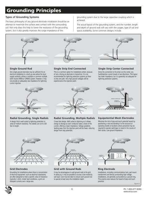
<strong>Grounding</strong> PrinciplesTypes of <strong>Grounding</strong> <strong>Systems</strong>The basic philosophy of any ground electrode installation should be anattempt to maximize the surface area contact with the surroundingsoil. Not only does this help to lower the resistance of the groundingsystem, but it also greatly improves the surge impedance of thegrounding system due to the large capacitive coupling which isachieved.The actual layout of the grounding system, <strong>and</strong> the number, length<strong>and</strong> depth of ground rods will vary with the usages, type of soil <strong>and</strong>space availability. Some common designs include:Single Ground RodOne single ground electrode may be sufficient for anelectrical installation in a built up area where the localsupply authority utilizes a multiple or common multipleearth neutral (MEN or CMEN) system. However, it maynot provide an adequately low impedance for lightningcurrent injection.Single Strip End ConnectedThis is a common option for installations where, becauseof rock, driving an electrode is impractical. It is notrecommended for lightning protection systems as thereis only one path. Very high ground voltages will beexperienced at the injection point.Single Strip Center ConnectedSince the connection to the strip is at the center, anyfault/injection current travels in two directions. This layouthas lower impedance, but it is generally not adequate forlightning protection systems.Radial <strong>Grounding</strong>, Single RadialsA design that is well suited to lightning protection inareas of medium resistivity. The radials can <strong>ru</strong>n to 100feet in length.Radial <strong>Grounding</strong>, Multiple RadialsCrows foot design. Well suited to lightning as it allowsenergy to diverge as each conductor takes a share of thecurrent, offering a lower impedance. Voltage gradientsleading away from the injection point will be lower, reducingdanger from step potentials.Equipotential Mesh <strong>Elec</strong>trodesMinimize the risk of step <strong>and</strong> touch potential hazard bypositioning a mat <strong>and</strong> bonding it to the st<strong>ru</strong>cture oroperating h<strong>and</strong>le at locations where personnel may berequired to operate switchgear or st<strong>and</strong> in the course oftheir duties. Low ground impedance.Grid <strong>Elec</strong>trodes<strong>Grounding</strong> for installations where there is concentrationof electrical equipment, such as electrical substations,are often designed to meet a specific value of resistance(typically 1 ohm). Under fault conditions, a grid c<strong>and</strong>issipate currents over a large area.Grid with Ground RodsIt may be advantageous to add ground rods to the grid.In doing so, it may be possible to access a low resistivitysoil layer. Care must be taken to ensure each ground rodis spaced at least twice the installation depth.Ring <strong>Elec</strong>trodeInstallations, including communications huts, pad mounttransformers <strong>and</strong> fences surrounding high voltageinstallations, are generally surrounded by a ground ring.This practice also reduces the hazard of step <strong>and</strong> touchpotential.Figure 8.6 Ph: 1-800-677-9089www.erico.com
<strong>Grounding</strong> PrinciplesGround / Earthing System Design<strong>Grounding</strong> systems are important. It is not expensive to build anappropriate ground system during initial const<strong>ru</strong>ction of a facility, butit can be very expensive to add to it, enhance it, or replace it after thefacility is complete. Care should be taken to design a system that isappropriate both for clearing ground faults <strong>and</strong> dissipating lightningenergy. The system must have a long performance life, meet applicablecodes / st<strong>and</strong>ards for safety, <strong>and</strong> have sufficient bonding points tomake it easy to add new equipment / facility grounding to it easily.Design considerations include:• Purpose of facility• Design life of facility• Soil resistivity at 3 depths• Corrosive nature of soil• Shape <strong>and</strong> available area of facility site• Existing st<strong>ru</strong>ctures <strong>and</strong> their grounding systems• Seasonal variations in moisture <strong>and</strong> temperature for facility site• Public access & personnel use• Adjacent facilities <strong>and</strong> electrical systems• Future uses, additions, equipment for facilityFor proper operation of overcurrent devices, it is important to have alow DC ohmic resistance to remote earth. In many instances, this isbest achieved by installing a deep ground electrode on site. It shouldbe driven deep enough to reach the permanent water table.For dissipation of direct or indirect lightning currents, it is better tohave many horizontal ground conductors in the soil, preferably in aradial array. This provides a low impedance path of dissipation to thehigh frequency component of the lightning energy.For safety of personnel, particularly where people congregate orwhere equipment operators will be located, it is important to have agrid system or other equipotential plane to reduce "step potential"<strong>and</strong> have equipment <strong>and</strong> metal st<strong>ru</strong>ctures bonded to the groundsystem to reduce "touch potential".A proper facility grounding system incorporates these necessities inthe most cost-effective manner that will last for the design life of thefacility.ERICO ® is a manufacturer <strong>and</strong> marketer of grounding, bonding,lightning protection <strong>and</strong> surge protection products <strong>and</strong> systems.ERICO has many knowledgeable <strong>and</strong> experienced engineers on staffwith the training <strong>and</strong> the tools (including some of the latest designsoftware) to design appropriate grounding systems. These engineerscan assist facility owners, engineers <strong>and</strong> contractors in designing themost appropriate system for the facility in question.<strong>Grounding</strong> Chain• <strong>Grounding</strong> <strong>Elec</strong>trode Conductor• <strong>Grounding</strong> Connections• <strong>Grounding</strong> <strong>Elec</strong>trode• <strong>Elec</strong>trode to Soil Resistance• SoilThe <strong>Grounding</strong> ChainThe performance of the grounding system is determined by the qualityof the following five components all of which are of equal importance.1. The <strong>Grounding</strong> <strong>Elec</strong>trode Conductor. Typically made from copperor copper-clad steel, the grounding electrode conductor must belarge enough to withst<strong>and</strong> the maximum available fault currentover the maximum clearing time.2. The <strong>Grounding</strong> Connections. Often overlooked, the groundingconnections are used to tie the elements of the electrode systemtogether. Exothermically welded connections provide a molecularbond that will never loosen or corrode. Mechanical connectors,such as crimp, bolted, <strong>and</strong> wedge type, rely on physical point-topointsurface contact to maintain the integrity of the electricalconnection. IEEE St<strong>and</strong>ard 837 provides detailed information onthe application <strong>and</strong> testing of permanent grounding connections.ERICO can provide an independent, third-party test reportevaluating the performance of these connectors in accordancewith the testing procedures set forth in IEEE 837 St<strong>and</strong>ard forQualifying Permanent Substation <strong>Grounding</strong> Connections.3. The <strong>Grounding</strong> <strong>Elec</strong>trode. The grounding electrode provides thephysical connection to the earth <strong>and</strong> is the inst<strong>ru</strong>ment used todissipate current into it. There are two main types of electrodes."Natural" electrodes are intrinsic to the facility <strong>and</strong> include metalunderground water pipe, the metal frame of the building (ifeffectively grounded), <strong>and</strong> reinforcing bar in concrete foundations."Made" electrodes are installed specifically to improve theperformance of the ground system <strong>and</strong> include wire meshes,metallic plates, buried copper conductor <strong>and</strong> rods or pipes driveninto the ground. The ground rod is the most widely usedelectrode.4. <strong>Elec</strong>trode to Soil Resistance. Amount of rod surface <strong>and</strong> rodreplacement are the controlling factors. Doubling diameter reducesresistance by only 10% <strong>and</strong> is not cost effective. Doubling rodlength, however, theoretically reduces resistance by 40%. Themost common solution is proper placement of multiple rods thatare driven to the required depths.5. The Soil. The soil resistivity, measured in ohm-centimeters or ohmmeters,plays a significant role in determining the overallperformance of the grounding system <strong>and</strong> must be known beforea proper grounding system can be engineered. Measuring soilresistivity allows the design engineer to locate an area with themost conductive soil <strong>and</strong> to determine the depth of theconductive soil so that electrodes can be placed accordingly.The grounding system will carry little or no current for long periods oftime until a fault occurs or a lightning strike or other transient requiresdissipation. At that point, the grounding system components will beexpected to perform like new while conducting large amounts ofcurrent. Most of the grounding system is concealed below grade,making inspection of the grounding components difficult orimpossible. The underground environment is a harsh one. The initialselection of the components used in the grounding system is of criticalimportance to its long-term effectiveness.Ph: 1-800-677-9089www.erico.com7