FCD-155: Ethernet and E1/T1/E3/T3 over SDH/SONET ... - comtec
FCD-155: Ethernet and E1/T1/E3/T3 over SDH/SONET ... - comtec
FCD-155: Ethernet and E1/T1/E3/T3 over SDH/SONET ... - comtec
- No tags were found...

You also want an ePaper? Increase the reach of your titles
YUMPU automatically turns print PDFs into web optimized ePapers that Google loves.
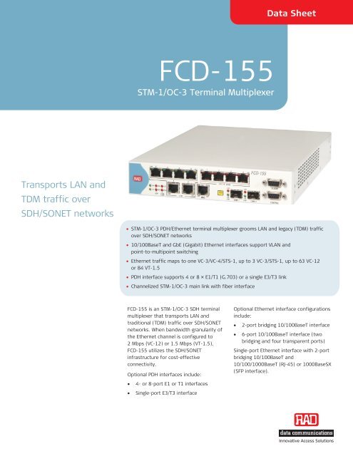
<strong>SDH</strong>/<strong>SONET</strong> media can transport basic<strong>Ethernet</strong> packets of up to 1536 bytesenabling connection to MPLS networks.The <strong>Ethernet</strong> interfaces allowinterconnection of SAN (Storage AreaNetworks) devices with <strong>Ethernet</strong> packetsup to 2 kb.Spanning Tree Protocol (STP) <strong>and</strong> RapidSpanning Tree Protocol (RSTP) supportLayer 2 ring applications.TDM INTERFACE<strong>FCD</strong>-<strong>155</strong> has an optional interface modulecontaining 4 or 8 <strong>E1</strong>/<strong>T1</strong> balanced interfaceports that transfer data transparently incompliance with the G.703 st<strong>and</strong>ard.The unbalanced <strong>E1</strong> interface is softwareselectable on the 8-port version. The4-port version is jumper-selectable <strong>and</strong>requires an adapter cable (see Ordering).An optional <strong>E3</strong>/<strong>T3</strong> port supports unframed<strong>E3</strong>/<strong>T3</strong> links <strong>over</strong> <strong>SDH</strong>/<strong>SONET</strong>.TDM traffic is mapped into <strong>SDH</strong>/<strong>SONET</strong>VC-12/VC-11/VC-3 or <strong>SONET</strong> V<strong>T1</strong>.5/STS-1containers that can be placed anywherewithin the STM-1/OC-3 b<strong>and</strong>width.MANAGEMENTRemote units can be managed in any ofthe following ways:• Via DCC using IP tunneling <strong>over</strong> OSIDCN based on ITU-T G.7712• IP/PPP <strong>over</strong> DCC protocol• Via dedicated virtual group containingat least one VC-12/VT-1.5 channel• Inside user traffic in a virtual groupseparated by the GFP Channel ID orVLAN tag• Out-of-b<strong>and</strong>, via direct connection toone of the LAN ports.Status <strong>and</strong> diagnostic information isdefined, configured, <strong>and</strong> monitored usingone of the following methods:• ASCII terminal connected to theV.24/RS-232 control port• Telnet host via management platformor LAN port• Network management station runningRADview, the RAD SNMP networkmanagement application• TFTP applications to update software<strong>and</strong> upload/download remoteconfigurations• ConfiguRAD via Web browser.DIAGNOSTICS<strong>FCD</strong>-<strong>155</strong> has comprehensive diagnosticcapabilities, including:• <strong>Ethernet</strong> <strong>and</strong> <strong>SDH</strong>/<strong>SONET</strong> linkmonitoring• Real-time alarms that alert the user offault conditions. Alarms are reportedto the management station <strong>and</strong>simultaneously relayed through a drycontact port.GENERALAn AC or DC power supply is provided withan alarm-activated fan for forced-aircooling.<strong>FCD</strong>-<strong>155</strong> is a compact st<strong>and</strong>alone unit.One or two units can be installedside-by-side in a 19-inch rack using theoptional rack-mount adaptor kit. Oneunit can be mounted on the wall using theoptional wall-mount adapter kit (seeOrdering).
Data SheetSPECIFICATIONSSTM-1/OC-3 MAIN LINK (NETWORK)Number of Ports1 (second link available for redundancy)Bit Rate<strong>155</strong>.52 Mbps ±20 ppmSFP SocketCharacteristics: See Table 1SPF options: See OrderingTimingInternal clockRec<strong>over</strong>ed from the STM-1/OC-3 interfaceExternal clock from PDH tributaryCompliance<strong>SDH</strong>: ITU-T G.957<strong>SONET</strong>: GR-253-coreFraming<strong>SDH</strong>: ITU-T G.707, G.708, G.709<strong>SONET</strong>: ANSI <strong>T1</strong>.105-1995, GR-253-coreLine CodeNRZLAN INTERFACE (OPTION)Port Types2 or 6 10/100BaseT ports1 GbECompatibilityRelevant sections of IEEE 802.3u, 802.3x,802.1D <strong>and</strong> 802.1QLAN Table2,048 MAC addresses (2U) <strong>and</strong> 8,182(GbE) with selectable automatic aging timeData Rate10BaseT: 10 Mbps100BaseT: 100 Mbps1000BaseT: 1000Mbps (Gigabit <strong>Ethernet</strong>)AutonegotiationConnectors (per port)RJ-45, shieldedSFP socket (for transceivers, see Ordering)<strong>E1</strong>/<strong>T1</strong> PDH INTERFACE (OPTION)Number of Ports4 <strong>E1</strong>, 4 <strong>T1</strong>, 8<strong>E1</strong>, or 8 <strong>T1</strong>CompatibilityITU-T Rec. G.703, unframedNominal Data Rate<strong>E1</strong>: 2.048 Mbps<strong>T1</strong>: 1.554 MbpsLine Code<strong>E1</strong>: HDB3<strong>T1</strong>: B8ZSImpedance<strong>E1</strong>: 120Ω balanced or 75Ω unbalanced<strong>T1</strong>: 100Ω balancedTable 1. SFP Interface CharacteristicsTransceiverWavelength[nm]Fiber Type[μm]TransmitterTypeConnectorTypeInput Power[dBm]Output Power[dBm]Typical Max.Range(min) (max) (min) (max) [km] [miles]STM-1/OC-3 UplinkSFP-1 1310 62.5/125 multimode VCSEL LC -30 -14 -20 -14 2 1.2SFP-2 1310 9/125 single mode Laser LC -28 -8 -15 -8 15 9.3SFP-3 1310 9/125 single mode Laser LC -34 -10 -5 0 40 24.8SFP-4 <strong>155</strong>0 9/125 single mode Laser LC -34 -10 -5 0 80 49.7SFP-11 Copper Uplink Coaxial cable 75Ω – Mini-BNC – – – – 0.135* 0.08*SFP-18a Tx - 1310Rx – <strong>155</strong>09/125 single mode(single fiber)Laser(WDM)LC -28 -8 -5 0 40 24.8SFP-18b Tx – <strong>155</strong>0Rx – 1310SFP-19a Tx – 1490Rx – 1570SFP-19b Tx – 1570Rx – 14909/125 single mode(single fiber)9/125 single mode(single fiber)9/125 single mode(single fiber)Laser(WDM)Laser(WDM)Laser(WDM)LC -28 -8 -5 0 40 24.8LC -30 -8 0 +5 80 49.7LC -30 -8 0 +5 80 49.7SFP-5 850 50/125 multimode VCSEL LC -17 0 -9.5 0 0.55 0.3SFP-6 1310 9/125 single mode Laser LC -20 -3 -9.5 -3 10 6.2SFP-7 <strong>155</strong>0 9/125 single mode Laser LC -22 -3 0 +5 80 49.7SFP-8D 1310 9/125 single mode Laser LC -21 -3 0 -4 40 24.8* Using RG59 B/U.GbE UserPort
<strong>FCD</strong>-<strong>155</strong>STM-1/OC-3 Terminal MultiplexerMaximum Line Attenuation36 dB (LTU mode)12 dB (DSU mode)TimingSource clock is rec<strong>over</strong>ed from the receivesignal coming from the remote <strong>E1</strong>/<strong>T1</strong> sideLocked to the <strong>SDH</strong>/<strong>SONET</strong> interface clockConnectors4-ports: RJ-45, shielded8-ports: 44-pin, D-type, female<strong>E3</strong>/<strong>T3</strong> PDH INTERFACE (OPTION)Number of Ports1CompatibilityITU-T Rec. G.703, unframedData Rate<strong>E3</strong>: 34.368 Mbps<strong>T3</strong>: 44.736 MbpsFramingUnframedLine Code<strong>E3</strong>: HDB3<strong>T3</strong>: B3ZSLine Impedance75ΩConnectorTwo BNC femaleTimingSource clock is rec<strong>over</strong>ed from the receivesignal from the remote <strong>E3</strong>/<strong>T3</strong> sideLocked to the <strong>SDH</strong>/<strong>SONET</strong> interface clockMANAGEMENT PORTSCONTROL PortInterface: V.24/RS-232Connector: 9-pin D-type, femaleFormat: AsynchronousBaud rate: 0.3–115.2 kbpsSelectable word format:7 or 8 bits, no parity, 7 bit odd or evenparityOut-of-B<strong>and</strong> AccessSingle <strong>Ethernet</strong> port <strong>FCD</strong>-<strong>155</strong> version:MNG ETH portOther <strong>FCD</strong>-<strong>155</strong> versions:ETH 1 <strong>and</strong> ETH 2 ports (through internal<strong>Ethernet</strong> switch)INDICATORSGeneralPWR (green) – PowerTST (yellow) – TestMAJ ALM (red) – Major alarmMIN ALM (red) – Minor alarmLOC SYNC LOSS (red) – Local loss ofsynchronization on the STM-1/OC-3linksREM SYNC LOSS (red) – Remote loss ofsynchronization on the STM-1/OC-3linksETH, MNG, GbE (per port)LINK (green) – LAN link integrityACT (yellow) – LAN data activity<strong>E1</strong>/<strong>T1</strong> PDH Interface (per port)SIG LOSS (red) – <strong>E1</strong> link signal lossAIS (red) – AIS on <strong>E1</strong> link<strong>E3</strong>/<strong>T3</strong> PDH InterfaceSIG LOSS (red) – <strong>E3</strong>/<strong>T3</strong> link signal lossSTM-1/OC-3 Main LinksSIG LOSS (red) – STM-1/OC-3 link signallossON LINE (green) – STM-1/OC-3 link isactive (indicator is on) or on st<strong>and</strong>by(indicator is blinking)GENERALPowerAC: 100 to 240 VAC ±10%,50 to 60 HzDC: –48 VDC (–40 to –72 VDC)Power Consumption30WAlarmsLast 100 alarms are time-stamped, stored,<strong>and</strong> available for retrievalAlarm Relay PortOperation: normally open,normally closed, using different pinsConnector: 9-pin, D-type, femalePhysicalHeight: 4.4 cm (1.7 in)Width: 21.5 cm (8.5 in)Depth: 30.0 cm (11.8 in)Weight: 2.4 kg (5.3 lb)EnvironmentTemperature: 0°–50°C (32°–122°F)Humidity: Up to 90%,non-condensingOrdering<strong>FCD</strong>-<strong>155</strong>/*/&/$STM-1/OC-3 Terminal MultiplexerNote: SFP transceivers are not included in thechassis for the uplink <strong>and</strong>/or the fiber GbEinterfaces (see SFP Transceivers).Legend* Power supply:AC 100 to 240 VAC48 –48 VDC&LAN interface:2U 2 bridging 10/100BaseT ports6U 2 bridging <strong>and</strong> 4 transparent10/100BaseT portsGE 1 10/100/1000BaseT (GbE)port, copper interface <strong>and</strong> SFPsocket$ PDH interface:4<strong>E1</strong> 4 × <strong>E1</strong> G.703 ports4<strong>T1</strong> 4 × <strong>T1</strong> G.703 ports8<strong>E1</strong> 8 × <strong>E1</strong> G.703 ports8<strong>T1</strong> 8 × <strong>T1</strong> G.703 ports<strong>E3</strong> 1 × <strong>E3</strong> G.703 port<strong>T3</strong> 1 × <strong>T3</strong> G.703 portNotes:The 4 x <strong>E1</strong> port option is delivered with abalanced <strong>E1</strong> interface.To convert the interface from balanced tounbalanced, use converter cableCBL-RJ45/2BNC/<strong>E1</strong>/X.<strong>FCD</strong>-<strong>155</strong>-PACK1Software key for activatingIP tunneling management option
<strong>FCD</strong>-<strong>155</strong>STM-1/OC-3 Terminal MultiplexerData SheetSFP TRANSCEIVERS(For redundancy, order two SFPtransceivers)STM-1/OC-3 UplinkSFP-1 STM-1/OC-3, 1310 nmmultimode VCSEL,LC connectorSFP-2 STM-1/OC-3, 1310 nm singlemode laser (S1.1),LC connectorSFP-3 STM-1/OC-3, 1310 nm, singlemode laser, long haul (L1.1),LC connectorSFP-4 STM-1/OC-3, <strong>155</strong>0 nm singlemode laser, long haul (L1.2),LC connectorSFP-11 STM-1/OC-3, electricalinterface, mini-BNC coaxialconnectorSFP-18a STM-1/OC-3, Tx – 1310,Rx – <strong>155</strong>0, 9/125 singlemode (single fiber), laser(WDM), LC connectorSFP-18b STM-1/OC-3, Tx – <strong>155</strong>0Rx – 1310, 9/125 singlemode (single fiber), laser(WDM), LC connectorSFP-19a STM-1/OC-3, Tx – 1490Rx – 1570, 9/125 singlemode (single fiber), laser(WDM), LC connectorSFP-19b STM-1/OC-3, Tx – 1570Rx – 1490, 9/125 singlemode (single fiber), laser(WDM), LC connectorGbE UserSFP-5 GbE, 850 nm multimodeVCSELSFP-6 GbE, 1310 nm single modelaser (LX-SM)SFP-7 GbE, <strong>155</strong>0 nm single modelaser, long haul LX-H (ZX)SFP-8D GbE, 1310 nm single modelaser, long haul (LX-H)Note: It is strongly recommended to order thisdevice with original RAD SFPs installed. This willensure that prior to shipping, RAD has performedcomprehensive functional quality tests on theentire assembled unit, including the SFP devices.RAD cannot guarantee full compliance to productspecifications for units using non-RAD SFPs.SUPPLIED ACCESSORIESAC power cord (when AC power supply isordered)DC adapter plug (when DC power supply isordered)CBL-DB9F-DB9M-STRControl port cableOPTIONAL ACCESSORIESCBL-RJ45/2BNC/<strong>E1</strong>/XCable for converting a balanced<strong>E1</strong> interface to an unbalanced <strong>E1</strong>interface. Contains one RJ-45 balancedconnector <strong>and</strong> two unbalanced BNCcoaxial connectors.CBL-SMB-BNC/M/ECable for adapting two mini-BNCconnectors to two full-sized BNCconnectors (for SFP-11)CBL-G703-8/^8<strong>E1</strong>/8<strong>T1</strong> interface cables for the DB-44port connector (one cable required perinterface):Legend* Connector type:RJ45 splits into 8 <strong>E1</strong>/<strong>T1</strong>balanced RJ-45 connectorsRJ45/X splits into 8 <strong>E1</strong>/<strong>T1</strong>balanced RJ-45 connectors(cross-cable)COAX splits into 8 pairs of <strong>E1</strong>unbalanced BNC maleconnectorsOPEN 8 × 4 unterminated freeleads 2m (6.6 ft)RM-35/@Hardware kit for mounting one or twounits in a 19-inch rackLegend@ Rack mount kit type:P1 Mounting one unitP2 Mounting two unitsWM-35Hardware for mounting one unit on thewall180-100-09/07 Specifications are subject to change without prior notice. © 1991–2007 RAD Data Communications Ltd. All other trademarks are the property of their respective holders.International Headquarters24 Raoul Wallenberg StreetTel Aviv 69719, IsraelTel. 972-3-6458181Fax 972-3-6498250, 6474436E-mail market@rad.comwww.rad.comNorth America Headquarters900 Corporate DriveMahwah, NJ 07430, USATel. 201-5291100Toll free 1-800-4447234Fax 201-5295777E-mail market@radusa.comInnovative Access Solutions