ECOBOX Heat Recovery Unit - VES
ECOBOX Heat Recovery Unit - VES
ECOBOX Heat Recovery Unit - VES
- No tags were found...

Create successful ePaper yourself
Turn your PDF publications into a flip-book with our unique Google optimized e-Paper software.
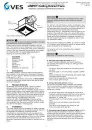
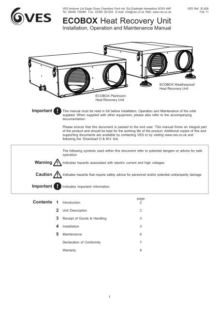
<strong>VES</strong><strong>VES</strong> Andover Ltd Eagle Close Chandlers Ford Ind. Est Eastleigh Hampshire SO53 4NFTel: 08448 156060 Fax: 02380 261204 E-mail: info@ves.co.uk Web: www.ves.co.uk<strong>ECOBOX</strong> <strong>Heat</strong> <strong>Recovery</strong> <strong>Unit</strong>Installation, Operation and Maintenance ManualReceipt of Goods& Handling3Immediately upon receipt of goods, check for possible damage in transit. In the event of anydamage having occurred or if any item is found to be missing, it is essential to inform <strong>VES</strong> AndoverLtd. within 7 days of delivery quoting sales order number and the unit type, as found on the unitnameplate. After this period, <strong>VES</strong> would be unable to accept any claim for damaged or missinggoods.ImportantLids, spigots and drain connections must not be used as lifting points.When moving the unit, handle with care and in such amanner as to avoid damaging the external finish.<strong>Unit</strong>s are to be rigged and lifted using spreaders,taking into account the weight of the unit. Lifting gearshould be arranged so as not to bear on thecasework.Installation 4ImportantLeft<strong>Unit</strong> rigged andlifted using spreadersThe entire system must be considered for safety purposes and it is the responsibility of the installerto ensure that all of the equipment is installed in compliance with the manufacturer’srecommendations, with due regard to the current HEALTH AND SAFETY AT WORK ACT andconforms to all relevant statutory regulations. Where a unit is installed so that a failure ofcomponents could result in injury to personnel, precautions should be taken to prevent such aninjury.Only experienced fitters should undertake this work. Take necessary safety precautions whenworking in elevated positions.It is the installer’s responsibility to ensure that access panels are not obstructed in any way andsafe working access for maintenance must be provided in line with Health and Safety and BuildingRegulations.For optimum unit performance, careful consideration must be paid to the location of the unit inrelation to the ductwork and associated items; it is advisable to maintain good working practice asdetailed within DW144. Consideration must also be given by the installer for adequate illuminationof the unit location in order for safe maintenance.<strong>Unit</strong>s are fitted with feet suitable for drop-rod mounting, with airflow in the horizontal plane.Alternatively Self levelling feet can be fitted for floor mounting, M10 fixings as per drop rods. Ifrequired the unit can be secured to the floor via knockout fixings holes fixings by others. Whenhanging units from drop-rods ensure that the load is evenly spread and that all feet are used withinthe support. When hanging the unit it is critical the unit is level to ensure the drain operatesaffectively. Secure drop rods/unit with M10 fixings as shown in . Standard units should bemounted in the horizontal plane, level with lid access to the top only. For alternative mounting pleaseconsult your outline drawing as supplied with the unit, or refer to <strong>VES</strong> Customer Services for furtherinformation.3
<strong>VES</strong><strong>VES</strong> Andover Ltd Eagle Close Chandlers Ford Ind. Est Eastleigh Hampshire SO53 4NFTel: 08448 156060 Fax: 02380 261204 E-mail: info@ves.co.uk Web: www.ves.co.uk<strong>ECOBOX</strong> <strong>Heat</strong> <strong>Recovery</strong> <strong>Unit</strong>Installation, Operation and Maintenance ManualInstallation 4 ContinuedWhere provided, flanges and spigots should not be used to support the ductwork andsolely as a means of ductwork connection.Where the drain pan is not required remove the compression nut and olive from tankconnector and replace with a standard tank connector end cap (supplied by others).Changing handing - all units are supplied left hand side as standard. The following givesinstructions for changing the handing:- Carefully remove the lid as shown- Remove the heat exchanger by carefully lifting straight up and out, taking carenot to damage the heat exchanger fins or seal whilst doing so.- Remove the spacer , again lifting straight up and out.- Using waterpump pliers or similar undo the connector on the outside of theunit. This secures the internal drain pan in place.- Withdraw the condensate drainpan and remove/retain the loose connector.- Remove/retain the sealing grommet from the drainpan.CautionWhen accessing the unit ensure the access panels are lowered in a controlled manner soas to avoid damage to the unit or injury to personnel.Components<strong>Heat</strong> ExchangerSupport trayDrain pan<strong>ECOBOX</strong> caseSealing grommetTank connectorThreaded insertLocking nut and washerCompression nut & olive(x1)(x1)(x1)(x1)(x2)(x1)4
<strong>VES</strong><strong>VES</strong> Andover Ltd Eagle Close Chandlers Ford Ind. Est Eastleigh Hampshire SO53 4NFTel: 08448 156060 Fax: 02380 261204 E-mail: info@ves.co.uk Web: www.ves.co.uk<strong>ECOBOX</strong> <strong>Heat</strong> <strong>Recovery</strong> <strong>Unit</strong>Installation, Operation and Maintenance ManualInstallation 4Continued- Remove insulation panels , & and retain .- Replace sealing grommet (removed/retained earlier) on the other side of drainpan .- Remove/retain the sealing grommet from the outside of the case. and replace on the otherside as shown .- Replace the drainpan on the opposite side of the unit as shown .- Replace the drain connector , through the drainpan and out of the case as shown andsecure into place the pump pliers or similar.- Replace the spacer ensuring the cutout section is adjacent to the drain for fit .- Replace the heat exchanger taking care not to damage the heat exchanger fins or sealwhilst doing so. This may require more than one person for larger units.- Re-orientate and replace insulation panels , & - where necessary secure withsilicon as shown .- Continued page 5.5
<strong>VES</strong><strong>VES</strong> Andover Ltd Eagle Close Chandlers Ford Ind. Est Eastleigh Hampshire SO53 4NFTel: 08448 156060 Fax: 02380 261204 E-mail: info@ves.co.uk Web: www.ves.co.uk<strong>ECOBOX</strong> <strong>Heat</strong> <strong>Recovery</strong> <strong>Unit</strong>Installation, Operation and Maintenance ManualInstallation 4Continued- It is recommended that once handing has been established, the heat exchanger is siliconsealed into position (locations as shown ) to assist with air-tightness.- Replace the lid and secure into position using the fitted latches.Maintenance 5All accompanying documentation, including warning labels must be referred to prior to carrying outany work on our units.Although there are no live or moving components within the ECOBox range care must be taken toensure any associated units are COMPLETELY ISOLATED and any moving parts are allowed tocome to rest as per associated Operational Manuals.<strong>ECOBOX</strong> units are as standard available in top access, units mounted in ceiling voids or similarmay need to be repositioned in order to access internal components.Recommended ChecksIn general, this series of units require very little maintenance. In the unlikely event of componentfailure, spares are available from stock at <strong>VES</strong> Andover Ltd..Plate heat exchanger units have no moving parts, therefore only minimal maintenance is required.Periodical inspection is recommended of the heat exchanger matrix for any debris, dust or dirt buildup. Simply remove the fixings/lid and inspect the plate heat exchanger for any debris.Note - Frequent contamination might be as a result of poor filtration and should be investigated.If found contaminated, foreign matter should be removed accordingly; superficial dust or debris canbe removed from the surface of the heat exchange matrix by gently brushing. Loosened debris canthen be vacuumed from the surface of the matrix or flushed through with warm water. Stubborndeposits can be removed by using a low pressure washer with an approved detergent solution. Thesolution temperature should not exceed 50 °C. When using any pressure device care must be takennot to damage the heat exchanger matrix. Under NO circumstances should the heat exchanger besteam cleaned. In addition to checking the heat exchanger, ensure the drain pan, in particular thedrain connection is free from debris ensuring any condensate produced can freely drain away.Spares & RepairsWhen enquiring after or ordering spares contact <strong>VES</strong> Spares Department, quoting the sales order(SO) number and unit type as found on the unit nameplate.Telephone 08448 15 60 60 • Fax 02380 26 12 04RecyclingAt the end of their useful life the packaging and product should be disposed of via a suitablerecycling centre. Do not dispose of with normal household waste. Do not burn.PLEASE ENSURE THAT THIS DOCUMENT IS PASSED ON TO THE END USERWe reserve the right to alter the specifcation without notice ©<strong>VES</strong> Andover Ltd. 2008.No part of this publication may be photocopied or otherwise reproduced without the prior permission in writingof <strong>VES</strong> Andover Ltd.6
<strong>VES</strong><strong>VES</strong> Andover Ltd Eagle Close Chandlers Ford Ind. Est Eastleigh Hampshire SO53 4NFTel: 08448 156060 Fax: 02380 261204 E-mail: info@ves.co.uk Web: www.ves.co.uk<strong>ECOBOX</strong> <strong>Heat</strong> <strong>Recovery</strong> <strong>Unit</strong>Installation, Operation and Maintenance ManualDeclaration of ConformityDate: 1st June 2008Product:Type:<strong>ECOBOX</strong> <strong>Heat</strong> <strong>Recovery</strong> <strong>Unit</strong>EBXManufacturer: <strong>VES</strong> Andover LimitedThe product above is produced in accordance with EC Council Directives:CE Marking 06/42/EC (Machinary Directive)Basis of Self attestation:Quality Assurance to ISO 9001-2000, BSI Reg. Firm Cert. No. Q5375Signature of Manufacturer:Position of Signatory:Technical Director7
<strong>VES</strong><strong>VES</strong> Andover Ltd Eagle Close Chandlers Ford Ind. Est Eastleigh Hampshire SO53 4NFTel: 08448 156060 Fax: 02380 261204 E-mail: info@ves.co.uk Web: www.ves.co.uk<strong>ECOBOX</strong> <strong>Heat</strong> <strong>Recovery</strong> <strong>Unit</strong>Installation, Operation and Maintenance ManualWarrantyAll <strong>VES</strong> Andover Products come with a one year guarantee from date of dispatch, which coversparts and labour.You can now extend this with the following options:Option 1.FREE extended WarrantyWe can offer you a maintenance agreement that keeps this equipment in tip-top condition.If you take out this agreement, we will extend the warranty free of charge for up to 5 years,providing the regular maintenance agreement remains in place.Option 2.12-24 Month Extended Warranty12-24 months from the date of dispatch. This can be covered at a cost of just 3% of ordervalue. (minimum charge £50.00).Option 3.12-36 Month Extended Warranty12-36 months from date of dispatch. For this cover, the charge is 6% of order value(Minimum charge £80)Please State which option you require when you place your order. A transferable certificate willthen be issued to you.Please note, this offer excludes condensing units. We would be happy to quote you for theseseparately.Register for separate spares reminders and get a 10% discountRegister for this free service and we will automatically send you a regular reminderdetailing the consumable spares for this unit, together with their current list prices.You will then be entitled to a 10% discount off any spares.To arrange any of these optionsPhone: 08448 15 60 60or Email: spares@ves.co.ukStating the sales order and reference number from the unit.8