LIMPET Ceiling Extract Fans - VES
LIMPET Ceiling Extract Fans - VES
LIMPET Ceiling Extract Fans - VES
- No tags were found...

Create successful ePaper yourself
Turn your PDF publications into a flip-book with our unique Google optimized e-Paper software.
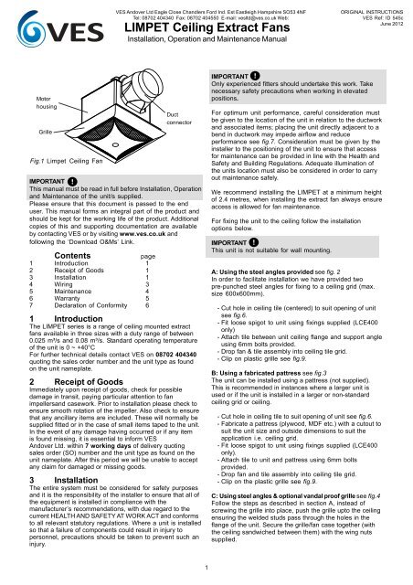
<strong>VES</strong> Andover Ltd Eagle Close Chandlers Ford Ind. Est Eastleigh Hampshire SO53 4NFTel: 08702 404340 Fax: 08702 404550 E-mail: vesltd@ves.co.uk Web:<strong>LIMPET</strong> <strong>Ceiling</strong> <strong>Extract</strong> <strong>Fans</strong>Installation, Operation and Maintenance ManualORIGINAL INSTRUCTIONS<strong>VES</strong> Ref: ID 545cJune 2012MotorhousingGrilleFig.1 Limpet <strong>Ceiling</strong> FanDuctconnectorIMPORTANTThis manual must be read in full before Installation, Operationand Maintenance of the unit/s supplied.Please ensure that this document is passed to the enduser. This manual forms an integral part of the product andshould be kept for the working life of the product. Additionalcopies of this and supporting documentation are availableby contacting <strong>VES</strong> or by visiting www.ves.co.uk andfollowing the ‘Download O&Ms’ Link.Contentspage1 Introduction 12 Receipt of Goods 13 Installation 14 Wiring 35 Maintenance 46 Warranty 57 Declaration of Conformity 61 IntroductionThe <strong>LIMPET</strong> series is a range of ceiling mounted extractfans available in three sizes with a duty range of between0.025 m³/s and 0.08 m³/s. Standard operating temperatureof the unit is 0 ~ +40°CFor further technical details contact <strong>VES</strong> on 08702 404340quoting the sales order number and the unit type as foundon the unit nameplate.2 Receipt of GoodsImmediately upon receipt of goods, check for possibledamage in transit, paying particular attention to fanimpellersand casework. Prior to installation please check toensure smooth rotation of the impeller. Also check to ensurethat any ancillary items are included. These will normally besupplied fitted or in the case of small items taped to the unit.In the event of any damage having occurred or if any itemis found missing, it is essential to inform <strong>VES</strong>Andover Ltd. within 7 working days of delivery quotingsales order (SO) number and the unit type as found on theunit nameplate. After this period we will be unable to acceptany claim for damaged or missing goods.3 InstallationThe entire system must be considered for safety purposesand it is the responsibility of the installer to ensure that all ofthe equipment is installed in compliance with themanufacturer’s recommendations, with due regard to thecurrent HEALTH AND SAFETY AT WORK ACT and conformsto all relevant statutory regulations. Where a unit is installedso that a failure of components could result in injury topersonnel, precautions should be taken to prevent such aninjury.IMPORTANTOnly experienced fitters should undertake this work. Takenecessary safety precautions when working in elevatedpositions.For optimum unit performance, careful consideration mustbe given to the location of the unit in relation to the ductworkand associated items; placing the unit directly adjacent to abend in ductwork may impede airflow and reduceperformance see fig.7. Consideration must be given by theinstaller to the positioning of the unit to ensure that accessfor maintenance can be provided in line with the Health andSafety and Building Regulations. Adequate illumination ofthe units location must also be considered in order to carryout maintenance safely.We recommend installing the <strong>LIMPET</strong> at a minimum heightof 2.4 metres, when installing the extract fan always ensureaccess is allowed for fan maintenance.For fixing the unit to the ceiling follow the installationoptions below.IMPORTANTThis unit is not suitable for wall mounting.A: Using the steel angles provided see fig. 2In order to facilitate installation we have provided twopre-punched steel angles for fixing to a ceiling grid (max.size 600x600mm).- Cut hole in ceiling tile (centered) to suit opening of unitsee fig.6.- Fit loose spigot to unit using fixings supplied (LCE400only)- Attach tile between unit ceiling flange and support angleusing 6mm bolts provided.- Drop fan & tile assembly into ceiling tile grid.- Clip on plastic grille see fig.9.B: Using a fabricated pattress see fig.3The unit can be installed using a pattress (not supplied).This is recommended in instances where a larger unit isused or if the unit is installed in a larger or non-standardceiling grid or ceiling.- Cut hole in ceiling tile to suit opening of unit see fig.6.- Fabricate a pattress (plywood, MDF etc.) with a cutout tosuit the unit size and outside dimensions to suit theapplication i.e. ceiling grid.- Fit loose spigot to unit using fixings supplied (LCE400only).- Attach tile to unit and pattress using 6mm boltsprovided.- Drop fan and tile assembly into ceiling tile grid.- Clip on the plastic grille see fig.9.C: Using steel angles & optional vandal proof grille see fig.4Follow the steps as described in section A, instead ofscrewing the grille into place, push the grille upto the ceilingensuring the welded studs pass through the holes in theflange of the unit. Secure the grille/fan case together (withthe ceiling sandwiched between them) with the wing nutssupplied.1
<strong>VES</strong> Andover Ltd Eagle Close Chandlers Ford Ind. Est Eastleigh Hampshire SO53 4NFTel: 08702 404340 Fax: 08702 404550 E-mail: vesltd@ves.co.uk Web:<strong>LIMPET</strong> <strong>Ceiling</strong> <strong>Extract</strong> <strong>Fans</strong>Installation, Operation and Maintenance Manual3 Installation continuedFig.2GA: Standard installation on ceiling tilesFig.3B: Installing unit with supporting pattressSupportanglesPattresssupplied byothers<strong>Ceiling</strong> tilewith cutout<strong>Ceiling</strong> tilewith cutoutRemovablespigot(LCE400 only)<strong>Extract</strong> fan unit,can be fittedabove or belowceiling tileRemovablespigot(LCE400 only)<strong>Extract</strong> fan unit,can be fittedabove or belowceiling tileRetainingfastenersRetainingfastenersInstalled viewGrille<strong>Extract</strong> fanunitInstalled viewGrille<strong>Extract</strong> fanunit<strong>Ceiling</strong> gridSupport angle<strong>Ceiling</strong> gridPattressCutout A<strong>Ceiling</strong> tileCutout A<strong>Ceiling</strong> tileFig.4C: Unit with vandal proof grilleFig.5D: Unit with special grilleWing nutsSupportanglesRemovablespigot(LCE400 only)<strong>Extract</strong> fan unit<strong>Ceiling</strong> cutoutRemovablespigot(LCE400 only)<strong>Extract</strong> fan unitGrille boxMounting anglesUnit base flange<strong>Ceiling</strong> tilewith cutoutInstalled viewVandal proofgrilleInstalled viewGrille<strong>Extract</strong> fanunitWing nutSupport angle<strong>Ceiling</strong> grid<strong>Extract</strong> fanunitGrille boxSupport angleCutout A<strong>Ceiling</strong>Cutout A<strong>Ceiling</strong> tile2
<strong>VES</strong> Andover Ltd Eagle Close Chandlers Ford Ind. Est Eastleigh Hampshire SO53 4NFTel: 08702 404340 Fax: 08702 404550 E-mail: vesltd@ves.co.uk Web:<strong>LIMPET</strong> <strong>Ceiling</strong> <strong>Extract</strong> <strong>Fans</strong>Installation, Operation and Maintenance Manual4 WiringAll electrical connections to any unit must be carried out inaccordance with the current edition of theI.E.E REGULATIONS and only competent electriciansshould be allowed to affect any electrical work to our units.Standard fan wiring arrangementFig.12 230 V 1Ph 50Hz supplyIMPORTANTIt is the customer’s responsibility to supply earth faultprotection through the building installation device and adedicated, isolated power supply with overload protectionto account for motor start up currents. Do not connect anyunit to an electrical supply voltage outside of that indicatedon the motor nameplate.A local isolator must be fitted and mains cables should besuitably sized and terminated as shown in fig.12 & 13.Electrical details are shown in fig.11.ESupplyNLTo connect the unit to a mains supply; remove the grillefrom the front of the unit, a terminal block mounted on thefan scroll see fig.10 will be clearly visible for connecting tothe supply. Feed the cable through the cable gland on theback of the unit see fig.10, into the fan section. Connect thesupply to the terminal block ensuring the wire is secured toavoid being drawn into the impeller.E N LFan connectionsFig.10 Cable entry & Terminal block locationPIR/fan wiring arrangementFig.13 230 V 1Ph 50Hz supply, wiring diagramto suit <strong>VES</strong> PIRs ESPIR/W1 & ESPIR/C1 ONLYGrilleCable glandSupplyLNETerminal blockE N LL1PIRGrilleENLFan connectionsModelMotor Input(W)Electrical DetailsFLC*(A)Fan Speed(RPM)Supply VoltageLCE160 35 0.09 1250 230 V 1Ph 50HzLCE250 60 0.16 1250 230 V 1Ph 50HzLCE400 45 0.21 1221 230 V 1Ph 50HzNote: If alternative PIR is to be used, manufacturers wiringdiagram and installation instructions must be consulted.Fig.11 Electrical details4
<strong>VES</strong> Andover Ltd Eagle Close Chandlers Ford Ind. Est Eastleigh Hampshire SO53 4NFTel: 08702 404340 Fax: 08702 404550 E-mail: vesltd@ves.co.uk Web:<strong>LIMPET</strong> <strong>Ceiling</strong> <strong>Extract</strong> <strong>Fans</strong>Installation, Operation and Maintenance Manual5 MaintenanceIMPORTANTBefore attempting to carry out any work on our units, the unitMUST BE COMPLETELY ISOLATED from its electrical supply.Ensure a minimum of two minutes after electricaldisconnection before commencing work. This will allow anymoving part to come to a restIn general, this series of units require very little maintenance.All fan and motor bearings are supplied fully lubricated andsealed for life. In the unlikely event of component failure,spares are available from stock at <strong>VES</strong> Andover Ltd.IMPORTANTBefore attempting to carry out maintenance work or repairwork on our units, all accompanying documentation includingwarning labels on the unit must be referencedRecommended checksEnsuring the unit is isolated:- Remove the grille see fig.9.- Clean the grille using luke warm water and lightdetergent (soap & water), rinse clean and dry throughly.- Ensure there is no build up of dust in the fan, vacuumclean or wipe with duster if necessary.- Refit the grille, again see fig.9.Failure to do this periodically could lead to a loss ofperformance or the fan to become out of balance, leadingultimately to bearing failure.IMPORTANTDo not clean the casework or grille with alkali solution orpowerful detergent as this will damage the finish. Do notspray water near the extract fan.WEEE DirectiveAt the end of their useful life the packaging andproduct should be disposed of via a suitablerecycling centre.Do not dispose of with normal household waste.Do not burnWhen enquiring after or ordering spares contact <strong>VES</strong>Spares Department, quoting the sales order (SO)number and unit type as found on the unit nameplate.Telephone 08702 40 43 40Fax 08702 40 45 50PLEASE ENSURE THAT THIS DOCUMENT ISPASSED ON TO THE END USER.We reserve the right to alter the specifcation without notice©<strong>VES</strong> Andover Ltd. 2012No part of this publication may be photocopied or otherwisereproduced without the prior permission in writing of <strong>VES</strong>Andover Ltd.5
<strong>VES</strong> Andover Ltd Eagle Close Chandlers Ford Ind. Est Eastleigh Hampshire SO53 4NFTel: 08702 404340 Fax: 08702 404550 E-mail: vesltd@ves.co.uk Web:<strong>LIMPET</strong> <strong>Ceiling</strong> <strong>Extract</strong> <strong>Fans</strong>Installation, Operation and Maintenance Manual6 WarrantyExtended WarrantiesAll <strong>VES</strong> Andover Products come with a one year guarantee from date of dispatch, which covers parts and labour.You can now extend this with the following options:Option 1.FREE extended WarrantyWe can offer you a maintenance agreement that keeps this equipment in tip-top condition.If you take out this agreement, we will extend the warranty free of charge for up to 5 years, providing the regular maintenanceagreement remains in place.Option 2.12-24 Month Extended Warranty12-24 months from the date of dispatch. This can be covered at a cost of just 3% of order value. (minimum charge£50.00).Option 3.12-36 Month Extended Warranty12-36 months from date of dispatch. For this cover, the charge is 6% of order value (Minimum charge £80)Please State which option you require when you place your order. A transferable certificate will then be issued to you.Please note, this offer excludes condensing units. We would be happy to quote you for these separately.Register for separate spares reminders and get a 10% discountRegister for this free service and we will automatically send you a regular reminder detailing the consumable spares forthis unit, together with their current list prices.You will then be entitled to a 10% discount off any spares.To arrange any of these options.Phone: 023 8046 1150or Email: spares@ves.co.ukStating the sales order and reference number from the unit.6
<strong>VES</strong> Andover Ltd Eagle Close Chandlers Ford Ind. Est Eastleigh Hampshire SO53 4NFTel: 08702 404340 Fax: 08702 404550 E-mail: vesltd@ves.co.uk Web:<strong>LIMPET</strong> <strong>Ceiling</strong> <strong>Extract</strong> <strong>Fans</strong>Installation, Operation and Maintenance ManualDeclaration of ConformityDate: 11th June 2012Product:Type:Manufacturer:Limpet Centrifugal <strong>Ceiling</strong> <strong>Fans</strong>LCE<strong>VES</strong> Andover LimitedThe product above is produced in accordance with EC Council Directives:2004/108/EC (Electromagnetic Compatibility Directive)2006/95/EC (Low Voltage Directive)The European Harmonised Standards applied are:BS EN ISO 12100, BS EN ISO 13857:2008, EN61000-6-2:2005, EN61000-6-3:2007,BS EN 60950-1:2006, BS EN ISO 5801:2008 (BS 848-1:2007)Basis of Self attestation:Quality Assurance to ISO 9001-2000, BSI Reg. Firm Cert. No. Q5375Signature of Manufacturer:Position of Signatory:Director7