Minimum gas speed in heat exchangers to avoid particulate fouling
Minimum gas speed in heat exchangers to avoid particulate fouling
Minimum gas speed in heat exchangers to avoid particulate fouling

You also want an ePaper? Increase the reach of your titles
YUMPU automatically turns print PDFs into web optimized ePapers that Google loves.
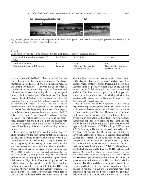
M.S. Abd-Elhady et al. / International Journal of Heat and Mass Transfer 47 (2004) 3943–3955 3947Fig. 3. Foul<strong>in</strong>g layer at the end of 9 h of operation for different flow <strong>speed</strong>s. The foulant is spherical glass particles of diameter 21 ± 16lm. (a) V ¼ 2:7 m/s; (b) V ¼ 3:8 m/s; (c) V ¼ 5 m/s.Table 1Comparison between the foul<strong>in</strong>g behaviors for glass particles under different operat<strong>in</strong>g conditionsAverage airflow <strong>speed</strong> between the HE V ¼ 2:7 m/s V ¼ 3:8 m/s V ¼ 5 m/stubesF<strong>in</strong>al thickness (mm) 1 0.75 0.3Circumferential and radial growth Cont<strong>in</strong>ues Starts very fast and thendecreases abruptlyStarts very fast and thendecreases abruptlyconcentration is 0.15 g/N m 3 of flow<strong>in</strong>g air. Fig. 3 showsthe foul<strong>in</strong>g layer at the end of operation for the abovementionedcases. Table 1 shows a comparison betweenthe three different cases. It is shown that as the <strong>speed</strong> ofthe flow <strong>in</strong>creases, the foul<strong>in</strong>g layer surface area andthickness are reduced. Increas<strong>in</strong>g the average air <strong>speed</strong>between the <strong>heat</strong> exchanger (HE) tubes from 2.7 <strong>to</strong> 5 m/sreduces the f<strong>in</strong>al foul<strong>in</strong>g layer thickness from 1 <strong>to</strong> 0.3mm after 9 h of operation. When the average flow <strong>speed</strong>between the HE tubes is 2.7 m/s, it is found that thecircumferential and radial growth of the foul<strong>in</strong>g layercont<strong>in</strong>ued from the beg<strong>in</strong>n<strong>in</strong>g till the end of the experiment.Increas<strong>in</strong>g the average flow <strong>speed</strong> between the HEtubes <strong>to</strong> 3.8 and 5 m/s showed a different foul<strong>in</strong>gbehavior. The foul<strong>in</strong>g rate was very high at the beg<strong>in</strong>n<strong>in</strong>g,especially for the first 3 h. Then the foul<strong>in</strong>g ratestarted <strong>to</strong> decrease abruptly for the next 6 h of operation,till hardly any radial or circumferential growth canbe seen.Figs. 4 and 5 show the growth of the foul<strong>in</strong>g layer forglass particles over the <strong>heat</strong> exchanger tube as a functionof time. The average air <strong>speed</strong> between the tubes is 2.7m/s for Fig. 4 and 3.8 m/s for Fig. 5. Fig. 4a shows thatat the beg<strong>in</strong>n<strong>in</strong>g of the foul<strong>in</strong>g process, some particlesstart <strong>to</strong> deposit at <strong>in</strong>termittent and distant positions.These po<strong>in</strong>ts of deposition start <strong>to</strong> grow radially, Fig.4b–e, till the whole surface of the <strong>heat</strong> exchanger tube iscovered completely with particles, Fig. 4f. The surficialgrowth of the foul<strong>in</strong>g layer is emphasized by the encircledareas <strong>in</strong> Figs. 4a–f. The surficial growth of thefoul<strong>in</strong>g layer can be expla<strong>in</strong>ed by the fact that f<strong>in</strong>eparticles are most likely <strong>to</strong> stick first <strong>to</strong> the HE tubesbecause of their higher stick<strong>in</strong>g velocity compared <strong>to</strong>coarse particles [7]. Then larger particles, which deposi<strong>to</strong>n the <strong>heat</strong> exchanger tube and stand alone <strong>in</strong> theshear<strong>in</strong>g flow, start <strong>to</strong> roll over the <strong>heat</strong> exchanger tubeif the shear<strong>in</strong>g flow <strong>speed</strong> is above a certa<strong>in</strong> limit. Theparticle roll<strong>in</strong>g motion is s<strong>to</strong>pped when it is blocked by astand<strong>in</strong>g heap of particles, which leads <strong>to</strong> the surficialgrowth of the fouled areas till they cover the unfouledsurfaces. The flow <strong>speed</strong> required <strong>to</strong> roll a particlerest<strong>in</strong>g on a flat surface, and, the stick<strong>in</strong>g velocity of aparticle, will respectively be discussed <strong>in</strong> detail <strong>in</strong> thefollow<strong>in</strong>g subsequent sections.Fig. 5 shows that at the beg<strong>in</strong>n<strong>in</strong>g of the foul<strong>in</strong>gexperiment, Fig. 5b, the glass particles <strong>in</strong> the flow started<strong>to</strong> deposit on the rear end of the HE tube and cont<strong>in</strong>ued<strong>to</strong> the circumference, Fig. 5c–e. The rear end of the <strong>heat</strong>exchanger, Fig. 5f, is subjected <strong>to</strong> the lowest shear<strong>in</strong>gforces due <strong>to</strong> separation of flow from the tube surface,Achenbach [9]. The flow field for the exam<strong>in</strong>ed HEshown <strong>in</strong> Fig. 1 is solved us<strong>in</strong>g the f<strong>in</strong>ite volume methodapplied by the commercial CFD-package CFX version4.2. The low Reynolds number k–e model is used <strong>to</strong> solvethe flow field around the HE tubes. For all but theadvection terms, use is made of a second-order centraldifferenc<strong>in</strong>g scheme. In the equations for the velocitycomponents, use is made of the third order QUICK<strong>in</strong>terpolation scheme for the advection terms. For the kand e equations the first order HYDRID-scheme is appliedwhich is more stable than the QUICK scheme andensures the k and e values <strong>to</strong> rema<strong>in</strong> positive <strong>in</strong> theconverged solution. In the computations use is made ofthe SIMPLEC pressure-correction scheme <strong>in</strong> which thepressure field is <strong>in</strong>directly specified via the cont<strong>in</strong>uityequation. For the u and the v velocity use is made of theS<strong>to</strong>ne’s method, for the turbulence quantities a l<strong>in</strong>erelaxationmethod is used and an algebraic multi-gridmethod is applied for the pressure equation. The flowfield is solved for a turbulent flow, at Re ¼ 2 10 5 , which