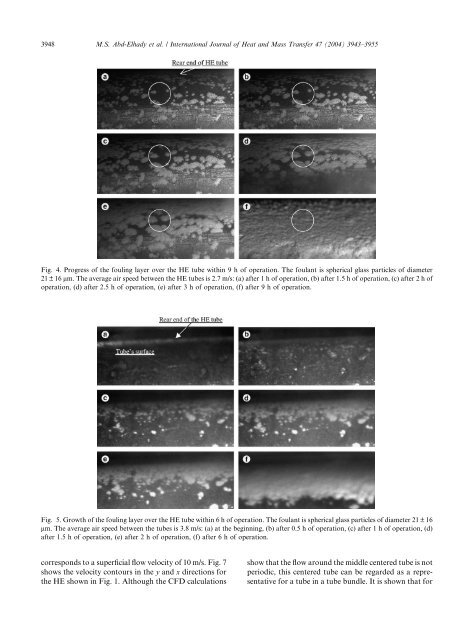
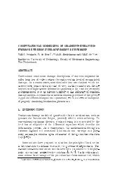
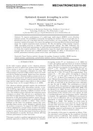
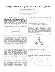
3948 M.S. Abd-Elhady et al. / International Journal of Heat and Mass Transfer 47 (2004) 3943–3955Fig. 4. Progress of the foul<strong>in</strong>g layer over the HE tube with<strong>in</strong> 9 h of operation. The foulant is spherical glass particles of diameter21 ± 16 lm. The average air <strong>speed</strong> between the HE tubes is 2.7 m/s: (a) after 1 h of operation, (b) after 1.5 h of operation, (c) after 2 h ofoperation, (d) after 2.5 h of operation, (e) after 3 h of operation, (f) after 9 h of operation.Fig. 5. Growth of the foul<strong>in</strong>g layer over the HE tube with<strong>in</strong> 6 h of operation. The foulant is spherical glass particles of diameter 21 ± 16lm. The average air <strong>speed</strong> between the tubes is 3.8 m/s: (a) at the beg<strong>in</strong>n<strong>in</strong>g, (b) after 0.5 h of operation, (c) after 1 h of operation, (d)after 1.5 h of operation, (e) after 2 h of operation, (f) after 6 h of operation.corresponds <strong>to</strong> a superficial flow velocity of 10 m/s. Fig. 7shows the velocity con<strong>to</strong>urs <strong>in</strong> the y and x directions forthe HE shown <strong>in</strong> Fig. 1. Although the CFD calculationsshow that the flow around the middle centered tube is notperiodic, this centered tube can be regarded as a representativefor a tube <strong>in</strong> a tube bundle. It is shown that for
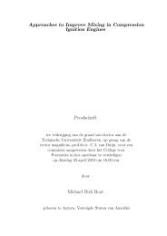
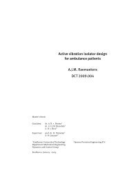
M.S. Abd-Elhady et al. / International Journal of Heat and Mass Transfer 47 (2004) 3943–3955 3949Fig. 6. A summary for the foul<strong>in</strong>g layer circumferential growth shown <strong>in</strong> Fig. 5.the middle centered tube the flow keeps attached <strong>to</strong> thetube surface and then separates at an angle of 120° fromthe stagnation po<strong>in</strong>t. From the numerical results it couldalso be concluded that there is more air circulation at thefront than <strong>in</strong> the rear end of the middle centered HEtube, Fig. 7c and d. Therefore particles that stick <strong>to</strong> therear end of the HE tube are more likely <strong>to</strong> rema<strong>in</strong> <strong>in</strong>position than particles that stick <strong>to</strong> the sides of the HEtube. A particle that sticks <strong>to</strong> the side of the HE tube rollsover the HE tube if the airflow <strong>speed</strong> is above a certa<strong>in</strong>limit, and s<strong>to</strong>ps if it is blocked by the rest<strong>in</strong>g particles atthe rear end of the <strong>heat</strong> exchanger tube. Therefore foul<strong>in</strong>gstarts at areas that are subjected <strong>to</strong> m<strong>in</strong>imum shear<strong>in</strong>gforces and then spreads due <strong>to</strong> particle transport <strong>to</strong>the already deposited particles. Fig. 6 summarizes thecircumferential growth of the foul<strong>in</strong>g layer shown <strong>in</strong> Fig.5.3.2. Limit<strong>in</strong>g foul<strong>in</strong>g <strong>speed</strong>The previous set of experiments has shown that asthe flow <strong>speed</strong> <strong>in</strong> the HE <strong>in</strong>creases, the thickness and thesurface area of the foul<strong>in</strong>g layer deposited over the HEtube are reduced. The follow<strong>in</strong>g experiments are done <strong>to</strong>determ<strong>in</strong>e the flow <strong>speed</strong> at which foul<strong>in</strong>g of the <strong>heat</strong>exchanger is prevented. The results of the experimentwill be compared <strong>to</strong> the results achieved with an analyticalmodel. The analytical model is only valid forspherical non-charged particles. The analytical model isbased on the m<strong>in</strong>imum shear velocity required <strong>to</strong> roll aparticle on a flat surface. It can be applied for a cyl<strong>in</strong>dricaltube if the particle diameter is much smaller thanthe cyl<strong>in</strong>der diameter, as is the case here. The shear flow<strong>speed</strong> required <strong>to</strong> roll a particle deposited on a flatsurface is called the critical flow velocity and it is afunction of the particle material and size and the surfacematerial. The critical flow velocity can be calculatedwhen assum<strong>in</strong>g that the hydrodynamic roll<strong>in</strong>g momentdue <strong>to</strong> the drag force, F d , lift force, F L , and buoyancyforce, F b , is greater than the rest<strong>in</strong>g adhesion momentdue <strong>to</strong> the surface adhesion force, F a , and the force ofgravity, F g . The ratio between the hydrodynamic roll<strong>in</strong>gmoment and the adhesion rest<strong>in</strong>g moment is def<strong>in</strong>ed byZhang et al. [10] as RM and equal <strong>to</strong>RM ¼¼Hydrodynamic roll<strong>in</strong>g momentAdhesion rest<strong>in</strong>g momentF d ð1:399R aÞðF a þ F g F b F L Þd=2 ; ð1Þwhere R, d and a are the particle radius, contact diameterand the particle radius of deformation, respectively.If the RM value is greater than 1, roll<strong>in</strong>g will takeplace. Abd-Elhady et al. [5] have calculated the criticalflow velocity for spherical copper particles of diametersrang<strong>in</strong>g from 5 <strong>to</strong> 50 lm, the results are shown <strong>in</strong> Fig. 8.The ma<strong>in</strong> flow stream velocity, i.e. the critical flowvelocity, required <strong>to</strong> roll a copper particle of 10 lm is10.5 m/s while for a 50 lm copper particle this velocity is4.5 m/s.Due <strong>to</strong> the comparison with the analytical modelpresented above, <strong>in</strong> the experiments only sphericalmetallic particles are used. The HE is operated at differentair flow<strong>in</strong>g <strong>speed</strong>s and different particle sizes <strong>to</strong>determ<strong>in</strong>e the operat<strong>in</strong>g <strong>speed</strong> at which foul<strong>in</strong>g is preventedas function of the particles size <strong>in</strong> the flow. Theflow <strong>speed</strong> at which foul<strong>in</strong>g is prevented, is <strong>in</strong>vestigatedfor copper particles of average diameter 10 lm with astandard deviation of 5 lm suspended <strong>in</strong> the airflow andalso for bronze particles of average diameter 55 lm witha standard deviation of 6 lm. The air temperature is 20°C and the particle concentration is 2 g/m 3 of airflow.The <strong>heat</strong> exchanger is kept runn<strong>in</strong>g for 8 h <strong>in</strong> eachexperiment. Experimental results of the foul<strong>in</strong>g experimentare plotted <strong>in</strong> Fig. 8. Fig. 8 shows that when air iscontam<strong>in</strong>ated with the copper particles of averagediameter 10 lm the HE tubes fouled when the averageflow <strong>speed</strong> between the tubes was lower than 9.5 m/s, i.e.