Minimum gas speed in heat exchangers to avoid particulate fouling
Minimum gas speed in heat exchangers to avoid particulate fouling
Minimum gas speed in heat exchangers to avoid particulate fouling

Create successful ePaper yourself
Turn your PDF publications into a flip-book with our unique Google optimized e-Paper software.
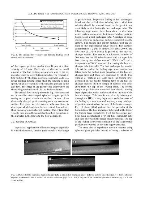
M.S. Abd-Elhady et al. / International Journal of Heat and Mass Transfer 47 (2004) 3943–3955 3951Air flow velocity (m/s) .1614121086420Copper particles0 10 20 30 40 50 60Particle's diameter (µm).of the copper particles smaller than 10 lm at a flowvelocity of 9.5 m/s. This could be due <strong>to</strong> the smallamount of the f<strong>in</strong>e particles present and due <strong>to</strong> the removalof them by larger hitt<strong>in</strong>g particles. The removal off<strong>in</strong>e particles by the large deposit<strong>in</strong>g particles leads <strong>to</strong> alower limit<strong>in</strong>g foul<strong>in</strong>g <strong>speed</strong> than the limit<strong>in</strong>g foul<strong>in</strong>g<strong>speed</strong>, which corresponds <strong>to</strong> the smallest particle <strong>in</strong> the<strong>gas</strong> flow. The effect of the particle size distribution onthe foul<strong>in</strong>g mechanism still has <strong>to</strong> be <strong>in</strong>vestigated.The critical flow velocity shown <strong>in</strong> Fig. 8 is calculatedfor a metallic non-charged spherical copper particlerest<strong>in</strong>g on a good conduc<strong>to</strong>r surface. In case of anelectrically charged particle rest<strong>in</strong>g on a bad conduc<strong>to</strong>rsurface like glass an electrostatic adhesion force isdeveloped which leads <strong>to</strong> a higher critical flow velocitythan <strong>in</strong> case of a non-charged particle. The critical flowvelocity then should be calculated based on the nature ofthe particles <strong>in</strong> the flow and the flow conditions.3.3. Stick<strong>in</strong>g of particlesCritical flow velocity (Theoretical).No Foul<strong>in</strong>g Condition (Experimental).Foul<strong>in</strong>g Condition (Experimental).Bronze particlesFig. 8. The critical flow velocity and limit<strong>in</strong>g foul<strong>in</strong>g <strong>speed</strong>versus particle diameter.In practical applications of <strong>heat</strong> <strong>exchangers</strong> especially<strong>in</strong> waste <strong>in</strong>c<strong>in</strong>era<strong>to</strong>rs, the flue <strong>gas</strong>es conta<strong>in</strong> a wide rangeof particle sizes. To prevent foul<strong>in</strong>g of <strong>heat</strong> <strong>exchangers</strong>based on the critical flow velocity, the critical flowvelocity should be selected based on the particle sizemost likely <strong>to</strong> stick first <strong>to</strong> the <strong>heat</strong> exchanger tubes. Thefollow<strong>in</strong>g experiments have been done <strong>to</strong> determ<strong>in</strong>ewhich particle size deposits first from a batch of particlesflow<strong>in</strong>g over a <strong>heat</strong> exchanger tube. A mixture of equalmasses of bronze and copper particles is <strong>in</strong>jected <strong>in</strong><strong>to</strong> theairflow. The bronze and copper particles used are def<strong>in</strong>ed<strong>in</strong> the experimental setup section. The particlesconcentration is 2 g/m 3 of airflow. Hot air at 200 °C andflow rate of 13E)3 Nm 3 /s is passed <strong>to</strong> the <strong>heat</strong> <strong>exchangers</strong>ection. This results <strong>in</strong> a Reynolds number of700 based on the HE tube diameter and the superficialflow velocity. An airflow rate of 1.5E)3 Nm 3 /s and atemperature of 20 °C was used for cool<strong>in</strong>g the <strong>heat</strong> exchangertube <strong>in</strong>ternally. The <strong>heat</strong> exchanger has run for9 h. At the end of the foul<strong>in</strong>g experiment samples aretaken from the foul<strong>in</strong>g layer deposited on the <strong>heat</strong> exchangertube and these are exam<strong>in</strong>ed by SEM. Twosamples of particles are taken from the foul<strong>in</strong>g layerdeposited on the middle centered tube of the <strong>heat</strong> <strong>exchangers</strong>ection: The first sample of particles was scratchedfrom the <strong>to</strong>p of the foul<strong>in</strong>g layer. The secondsample of particles was scratched from the first foul<strong>in</strong>glayer of particles, which had deposited on the tube of the<strong>heat</strong> exchanger. This sample was taken by blow<strong>in</strong>g airthrough the HE at a very high <strong>speed</strong> such that most ofthe foul<strong>in</strong>g layer was blown off and only a very th<strong>in</strong> layerof particles rema<strong>in</strong>ed on the tube of the <strong>heat</strong> exchanger.Fig. 10 shows SEM pictures for the particles at thebot<strong>to</strong>m (near the <strong>heat</strong> exchanger tube) and at the <strong>to</strong>p ofthe foul<strong>in</strong>g layer respectively. First the f<strong>in</strong>e copper particleshave accumulated over the <strong>heat</strong> exchanger tubeand then afterwards the larger bronze particles. The <strong>to</strong>pof the foul<strong>in</strong>g layer consisted ma<strong>in</strong>ly of the large bronzeparticles surrounded by the f<strong>in</strong>e copper particles.The same k<strong>in</strong>d of experiment above is repeated us<strong>in</strong>gspherical glass particles <strong>in</strong>stead of us<strong>in</strong>g a mixture ofFig. 9. Pho<strong>to</strong>s for the exam<strong>in</strong>ed <strong>heat</strong> exchanger tube at the end of operation under different airflow velocities: (a) V ¼ 2 m/s, a bronzelayer of thickness 0.3 mm is formed on the HE steel tube; (b) V ¼ 4:5 m/s, a very f<strong>in</strong>e layer of bronze particles is formed; (c) V ¼ 5:5 m/s, no foul<strong>in</strong>g.