
You also want an ePaper? Increase the reach of your titles
YUMPU automatically turns print PDFs into web optimized ePapers that Google loves.
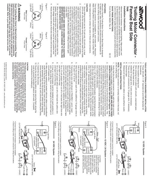
3®<strong>Trolling</strong> <strong>Motor</strong> <strong>Connector</strong> -Female Boat Side7648Installation Instructions<strong>Attwood</strong> marine hardware, navigational lighting, bilge pumps, andother marine accessories are specified more than any other brandby America’s best-known boat manufacturers as original equipment.Look to <strong>Attwood</strong> for quality replacement parts and marine accessories.SAVE THESE INSTRUCTIONSForm Number 69229 Rev. B 03-12FEATURES<strong>Attwood</strong>’s Female <strong>Trolling</strong> <strong>Motor</strong> <strong>Connector</strong> (Boat Side) is designedto make quick, safe connections and disconnections between anelectric trolling motor and a boat’s power source.This female connector is compatible to, and mates with, <strong>Attwood</strong>’sMale <strong>Trolling</strong> <strong>Motor</strong> connector (<strong>Motor</strong> Side), model number 7647.Ideal replacement for similar two-wire or three-wire connectors.CAUTION1. Since trolling motors can be 12-volt only, 24-volt only, or dual24/12-volt, only the necessary wiring connections need to be made.2. If you are wiring this female connector to mate with an existingmale connector, verify that the pin patterns match perfectly andthe existing connector is wired so that pin voltages correspond tothose displayed in your trolling motor owner’s manual. If they donot correspond, one connector or the other must be rewired sothat they do match. Or the existing unmatched male connectorcan be replaced with <strong>Attwood</strong>’s Male Trollling <strong>Connector</strong> (partnumber 7647).NEVER SHORT ONE WIRE OR CONNECTOR PIN TO ANOTHER.IMPROPER WIRING COULD CAUSE DAMAGE TO TROLLINGMOTOR AND/OR BATTERY.3. Wire a fuse or circuit breaker into each positive wire near thebattery. See trolling motor owner’s manual for correct fuse size.Dual voltage motors will require a fuse for each positive wire.4. Route and secure wires so that wire insulation will not be worn away.Figure 1Figure 2(-) Ground(Black)(-) Ground(Black)(+) 24 VDC(Light Blue)(+) 12 VDC(Yellow)(+) 12 VDC(Yellow)(+) 24 VDC(Light Blue)Male <strong>Connector</strong>Front ViewFemale <strong>Connector</strong>Front ViewWARNINGRead <strong>Trolling</strong> <strong>Motor</strong> Owner’s Manual before proceeding. Theseinstructions are general and may not meet your requirements.High electrical current carrying conductors are dangerous andcan cause personal injury and may start a fire if not correctlyinstalled. Refer to your dealer authorized service center.TOOLS AND MATERIALS REQUIRED FOR INSTALLATION1. Power drill with 1-1/8" diameter bit and 9/64 diameter bit2. Screwdriver3. Wire insulation stripping tool4. Wire crimping tool or pliers with smooth, unserrated jaws5. Two #8 pan-head screws6. Additional 10-gauge wire, if extra wire is necessary7. Three wire butt connectors for 10-gauge wire, if necessary8. Electrical tape9. Waterproof sealant (silicone rubber or polyurethane caulk)INSTALLATION INSTRUCTIONSNOTE: This female connector is normally installed in the boat, noton the trolling motor.1. Verify that this female connector mates with the male connectorinstalled, or to be installed, in your boat. PINS AND PIN VOLTAGESON BOTH CONNECTORS MUST MATCH (see Figures 1 and 2).2. Select a suitable location to mount this female connector. Themounting location should be in a non-structural area so the boatwill not be weakened. Mounting area should have a nearly verticalsurface to prevent water entry into the connector, and the areashould provide for easy access to wires while allowing for simplewire routing to the battery(s).3. Drill a 1-1/8" hole in the desired location. Insert the female connectorwith the door hinge upward, and mark the location of each of thetwo mounting holes with pencil or scribe. Set the connector aside.Drill a 1/8" diameter hole at each of the scribed areas.4. Install a splice connector on each of the 3 wires on the trollingmotor connector. Firmly crimp the splice connector onto the wireusing a crimping tool or smooth-jawed pliers. Performing thisprocedure on all three wires helps prevent short circuits, even ifonly 2 wires are needed.5. Strip the insulation from each of the additional 10-gauge wires tobe used 1/4" to 5/16".6. Following the color code shown in FIGURES 1 and 2, inserteach stripped wire end into the corresponding insulated splice.Securely crimp each splice connection with a crimping toolwhich will not damage the splice insulation. Wrap electrical tapearound each splice connection for additional insulation.7. On a 12-volt system either cut off or fold back the light blue wireand tape it out of the way.8. On a 24-volt system either cut off or fold back the yellow wireand tape it out of the way.9. A fuse or circuit breaker must be installed on each positive (+)wire. (See trolling motor owner’s manual for the correct fuse orcircuit breaker size.)10. After applying waterproof sealant (silicone rubber or polyurethanecaulk) to the back of the face plate, insert the female connector(wire assembly first) into the previously drilled hole keepingscrew mounting holes lined up with previously drilled pilot holes.11. Install the two #8 screws.12. Route the wiring to the battery area securing them along theroute to prevent insulation abrasion and wear. Completeconnections to the battery(s).CAUTIONThe following electrical schematics are for reference onlyand do not necessarily represent the hook up required foryour electrical accessory. Refer to the owner’s manual andcheck with your nearest authorized dealer service centerfor assistance prior to following any of these or attemptingto make installation yourself. Not doing so may void youraccessory warranty.© 2003 <strong>Attwood</strong> Corporation1016 N. Monroe Street, Lowell, MI 49331-0260 www.attwoodmarine.comFigure 312 VDC SystemYellowFuse12 VDCBatteryBlackYellow7648 7647Yellow + Black = 12VDCYellowBlackLight Blue:(CUT OR FOLD BACK AND TAPE)Light Blue:(CUT OR FOLD BACK AND TAPE)• Correct fuse or circuit breaker must be installed.• Check trolling motor owner's manual for rating and location.Figure 412 VDC / 24 SystemFuseLight BlueYellowLight Blue12 VDCBatteryYellowFuse4 AWG HEAVYJUMPER WIRE(not supplied)12 VDCBatteryBlack7648 7647CAUTION:A HEAVY-DUTY, 3-POSITIONSWITCH WITH CENTEROFF, SUCH AS A DUALBATTERY SWITCH, MAYBE REQUIRED FOR YOURINSTALLATION. CHECKYOUR TROLLING MOTOROWNER'S MANUALBEFORE INSTALLATION.Yellow + Black = 12VDCYellowBlackLight BlueLight Blue + Black = 24VDC• Correct fuse or circuit breaker must be installed.• Check trolling motor owner's manual for rating and location.Figure 524 VDC SystemLight BlueFuse12 VDCBattery4 AWG HEAVYJUMPER WIRE(not supplied)12 VDCBatteryBlack Yellow:(CUT OR FOLD BACK AND TAPE)BlackLight Blue76487647BlackLight BlueYellow:(CUT OR FOLD BACK AND TAPE)Light Blue + Black = 24VDC• Correct fuse or circuit breaker must be installed.• Check trolling motor owner's manual for rating and location.
3®Moteur Électrique RaccordFemelle - Côté du Bateau7648InstallationL’équipement maritime, l’éclairage de navigation, les pompes decale et autres matériels marins d’<strong>Attwood</strong> sont plus recommandésque tout autre équipement comme matériel d’origine par les fabricantsde bateaux les plus renommés d’Amérique. <strong>Attwood</strong> vous offredes pièces de rechange et des accessoires marins de qualité.CONSERVEZ CES INSTRUCTIONSFormulaire Numéro 69229 Rev. B 03-12CARACTÉRISTIQUESLe raccord femelle <strong>Attwood</strong> pour moteur électrique (côte du bateau)permet de brancher ou de débrancher rapidement et en toutesécurité le moteur électrique à la source de pouvoir du bateau.Ce raccord femelle est compatible avec le raccord mâle <strong>Attwood</strong>pour moteur électrique (côte du moteur), modèle numéro 7647.Remplacement idéal pour les raccords avec deux ou trois fils.ATTENTION1. Puisque les moteurs électriques peuvent fonctionner soit sur 12volts, soit sur 24 volts ou soit sur une combinaison de 24/12 volts,ne faites que les raccords de fils nécessaires.2. Si vous branchez ce raccord femelle à un raccord màle déjàprésent, assurez-vous que la position des fiches est identique etque les fils du raccord présent sont intallés de façon à ce que levoltage est le même que celui indiqué dans le manuel de votremoteur électrique. Si la position des fiches n’est pas identique,vous devez brancher l’un des raccords afin d’obtenir cette positionidentique. Ou, remplacez le raccord mâle déjà présent non identiqueavec un raccord femelle <strong>Attwood</strong> pour moteur électrique modèlenuméro 7647.NE JAMAIS COURT-CIRCUITER UN FIL OU UNE FICHE DERACCORD À UNE AUTRE. UNE MAUVAISE INSTALLATIONPEUT ENDOMMAGER LE MOTEUR ÉLECTRIQUE ET/OULA BATTERIE.3. Installez un fusible ou disjoncteur sur chaque fil positif près de labatterie. Consultez le manuel du moteur électrique pour savoirquels fusibles sont appropriés. Les moteurs à double voltagenécessitent un fusible sur chaque fil positif.4. Placez et fixez les fils pour éviter de déplacer les matières isolantes.Tableau 1(-) Mise àla masse(Fil noir)Tableau 2(-) Mise àla masse(Fil noir)(+) 24 V CD(Fil bleu pâle)(+) 12 V CD(Fil jaune)(+) 12 V CD(Fil jaune)(+) 24 V CD(Fil bleu pâle)Illustration De FaceDu Raccord MâleIllustration De FaceDu Raccord FemelleAVERTISSEMENTAvant de commencer, lisez le manuel du moteur électrique. Cesinstructions sont générales et ne sont peut-être pas adaptées àvos besoins. Les conducteurs électriques à haute puissancesont dangereux et peuvent entraîner des blessures personnelleset provoquer un incendie si l’installation n’est pas conforme.Consultez le centre de service de votre concessionnaire autorisé.OUTILS ET ARTICLES NÉCESSAIRES À L’INSTALLATION1. Perceuse électrique de 1-1/8" et un foret de 9/64"2. Tournevis3. Pince à dénuder les fils4. Pince à sertir ou pince sans dents5. Deux vix n° 8 à tête tronconique6. Au besoin, un morceau de fil supplémentaire de calibre 107. Au besoin, trois contacts à pression directe pour du fil de calibre 108. Ruban électrique9. Produit d’étanchéité (en silicone caoutchoutée ou en polyuréthanne)INSTALLATIONNOTE: Ce raccord femelle est habituellement branché dans le bateauet non pas sur le moteur électrique.1. Vérifiez que les fiches de ce raccord femelle sont identique àcelles du raccord mâle déjà installeé, ou que vous allez installerdans votre bateau. LES FICHES AINSI QUE LEUR VOLTAGEDOIVENT ÊTRE IDENTIQUES SUR LES DEAUX RACCORDS(voir TABLEAUX 1 et 2).2. Choisissez un endroit approprié pour installer ce raccord femelle.Choisissez un endroit non travaillant afin de ne pas affaiblir lebateau. La surface d’installation doit être presque verticale pouréviter une infiltration d l’eau dans le raccord; la surface doitégalement offrir un accès facile aux fils tout en permettant unacheminement simple vers la(les) batterie(s).3. Percez un trou de 1-1/8" à l’endroit voulu. Placez le raccordfemelle, gond de porte vers le haut, et induquez l’emplacementde chaque trou avec un crayon ou un trusquin. Placez le raccordde côté. Percez un trou de 1/8" à chaque endroit indiqué.4. Installez un raccord à dénuder sur chacun des trois fils duraccord du moteur électrique. À l’aide d’une pince à sertir oupince sans dents, ondulez fermement ce raccord sur le raccorddu fil. Cette manoeuvre effectuée sur les trois fils permet d’éviterles court-circuits si seulement 2 fils sont utilisés.5. Dénudez de 1/4" à 5/16" de chaque fil supplémentaire de calibre 10.6. Conformément aux codes colorés de TABLEAUX 1 et 2, placezchaque fil dénudé dans le raccord isolé approprié. À l’aide d’unepince à sertir, ondulez ce raccord pour éviter d’endommager lagaine isolante. Enveloppez du ruban électrique autour dechaque raccord afin d’ajouter de l’isolation.7. Avec un système de 12 volts, coupez ou repliez le fil bleu pâle età l’aide d’un ruban adhésif, placez-le à l’écart.8. Avec un système de 24 volts, coupez ou repliez le fil jaune et àl’aide d’un ruban adhésif, placez-le à l’écart.9. Vous devez installer un fusible ou disjoncteur sur chaque filpositif (+). (Consultez le manuel du moteur électrique poursavoir quels fusibles ou disjoncteurs sont appropriés.)10. Après l’application d’un produit d’étanchéité (en siliconecaoutchoutée ou en polyuréthanne) à l’arrière de la plaque demontage, placez le raccord femelle (les fils en premier) dans le trouapproprié en alignant les trous des vis avec les trous de la surface.11. Installez les deux vis n° 8.12. Acheminez les fils vers la batterie tout en les fixant pour éviterd’endommager l’isolant. Terminez l’installation des raccords àla(aux) batteries(s).ATTENTIONLes schémas électriques suivants sont destinés commeréférence seulement et ne représentent pas nécessairement lesraccords nécessaires à votre accessoire électrique. Consultez lemanuel ainsi que le centre de service de votre concessionnaireautorisé avant d’entreprendre l’installation vous-même. Sinon,vous risquez d’annuler la garantie de votre accessoire.© 2003 <strong>Attwood</strong> Corporation1016 N. Monroe Street, Lowell, MI 49331-0260 www.attwoodmarine.comTableau 3Système de 12 Volts CDJauneFusibleBatterie12 VoltsCDNoirJauneJaune + Noir = 12 Volts CD7648 7647JauneNoirBleu Pâle:(COUPEZ OU REPLIEZET ENROBEZ DE RUBAN)Bleu Pâle:(COUPEZ OU REPLIEZET ENROBEZ DE RUBAN)• Installez fusible ou disjoncteur appropriés.• Consultez le manuel pour l’installation et le calibre.Tableau 4Système de 12/24 Volts CDFusibleJauneBleu PâleBatterie12 VoltsCDJauneBleu PâleFusibleFIL DERACCORD DE4 AWG (non inclus)Batterie12 VoltsCDNoirATTENTION:UN COMMUTATEUR À3 POSITIONS (ARRÉT ENPOSITION CENTRALE),COMME LES COMMUTATEURSPOUR DOUBLE BATTERIE,PEUT ÉTRE NÉCESSAIREÀ VOTRE INSTALLATIION.CONSULTEZ LE MANUELAVENT LINSTALLATION.Jaune + Noir = 12 Volts CD7648 7647JauneNoirBleu PâleBleu Pâle + Noir = 24 Volts CD• Installez fusible ou disjoncteur appropriés.• Consultez le manuel pour l’installation et le calibre.Tableau 5Système de 24 Volts CDBleu PàleFusibleBatterie12 VoltsCDFIL DERACCORD DE4 AWG (non inclus)Batterie12 VoltsCDNoirJaune:(COUPEZ OU REPLIEZET ENROBEZ DE RUBAN)Noir 76487647NoirBleu PàleJaune:(COUPEZ OU REPLIEZET ENROBEZ DE RUBAN)Bleu PàleBleu Pâle + Noir = 24 Volts CD• Installez fusible ou disjoncteur appropriés.• Consultez le manuel pour l’installation et le calibre.