Infrared Imaging System for Analysis of Blood Vessel Structure
Infrared Imaging System for Analysis of Blood Vessel Structure
Infrared Imaging System for Analysis of Blood Vessel Structure

Create successful ePaper yourself
Turn your PDF publications into a flip-book with our unique Google optimized e-Paper software.
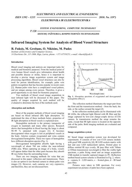
ELECTRONICS AND ELECTRICAL ENGINEERINGISSN 1392 – 1215 2010. No. 1(97)ELEKTRONIKA IR ELEKTROTECHNIKAT 120SYSTEM ENGINEERING, COMPUTER TECHNOLOGYSISTEMŲ INŽINERIJA, KOMPIUTERINĖS TECHNOLOGIJOS<strong>Infrared</strong> <strong>Imaging</strong> <strong>System</strong> <strong>for</strong> <strong>Analysis</strong> <strong>of</strong> <strong>Blood</strong> <strong>Vessel</strong> <strong>Structure</strong>R. Fuksis, M. Greitans, O. Nikisins, M. PudzsInstitute <strong>of</strong> Electronics and Computer Science,14 Dzerbenes Str., LV-1006, Riga, Latvia, phone: +371 67558251; e-mail: rihardsf@edi.lvIntroduction<strong>Blood</strong> vessel imaging and analysis are important tasks <strong>for</strong>medical and biometric purposes. From the medical point <strong>of</strong>view human blood vessels give in<strong>for</strong>mation about healthand possible disease or stroke, hence it is important todevelop a precise image acquisition system and imageprocessing algorithms. <strong>Blood</strong> vessel structures can also beused <strong>for</strong> person identification, <strong>for</strong> example, palm veinpattern recognition that has become popular in recent years[2]. Human palm veins have a complicated vessel pattern,and are unique among every person. There<strong>for</strong>e, it gives agood opportunity to use them <strong>for</strong> biometric purposes.Two methods <strong>of</strong> blood vessel image acquisition innear infrared light will be discussed in this paper. Thequality <strong>of</strong> images acquired by each method will beevaluated to determine the best <strong>of</strong> the methods used.Absorption and methodsMost <strong>of</strong> the popular methods <strong>of</strong> blood vessel imagingare based on blood infrared (IR) light absorption. Tounderstand the idea <strong>of</strong> these methods better, properties <strong>of</strong>IR light absorption in blood vessels is explained next.Hemoglobin molecule is the primary transporter <strong>of</strong>oxygen in mammals and many other species. Researchshows that hemoglobin in blood leaving the lungs is about98–99 % saturated with oxygen [1]. It becomesdeoxygenated when oxygen is lost at peripheral vessels inthe body. Arteries contain oxygenated and veins containdeoxygenated hemoglobin. These two types <strong>of</strong> hemoglobinhave different absorption spectra (Fig. 1).Deoxygenated hemoglobin absorbs light having awavelength <strong>of</strong> about 760 nm within the near-infrared(NIR) area. When capturing an image <strong>of</strong> a body, vesselswill appear darker than the other parts because they absorbIR rays better than the surrounding tissue.There are two imaging methods <strong>for</strong> veins that arediscussed in this paper: reflection and transmission. Thereis also an option to use thermal camera to obtain palm veinimages [3]. However, such cameras are very expensive,and there<strong>for</strong>e, they are not discussed here.Fig. 1. Absorption spectrum <strong>of</strong> oxygenated and deoxygenatedhemoglobin (Hb) [1]The reflection method illuminates the target part fromthe front and the transmission method − from the back, theside, or the surface around the target [2].In the reflection method palm can be illuminated withIR LEDs, the reflected light filtered with IR filter and theimage captured by low-cost charge-couple device (CCD)camera. In transmission method the setup remains thesame, except that IR light source is located on the oppositeside <strong>of</strong> the palm. Both imaging methods are evaluated andcompared.Image acquisition systemPC based image acquisition system was developed <strong>for</strong>experiments. It consists <strong>of</strong> low cost CCD camera modulewith good NIR sensitivity [4], IR LED sockets matrix withfast and easy LED replacement option, frosted glass todiffuse emitted IR rays evenly, IR pass filter with 760nmor 850nm transmission wavelength to filter the visible lightspectrum, a palm fixing stand and an image acquisitionUSB module to transfer captured images to PC. Reflectionmethod based system scheme is illustrated in Fig. 2, where:a – camera, b – LED matrix, c – frosted glass, d – IR bandpass filter.Pictures were taken in NIR spectrum. For everyexperiment ten pictures <strong>of</strong> palm have been captured.45
Fig. 2. Image acquisition system setupExperimentsIn the first experiment seven narrow-band IR LEDswith different wavelengths were used. The images <strong>for</strong> each<strong>of</strong> the wavelengths from 760−940 nm were acquired usingthe reflection method. To gain more in<strong>for</strong>mation aboutillumination properties <strong>of</strong> blood vessels no IR filters wereused in this experiment.In the second experiment only two differentwavelengths <strong>of</strong> IR LEDs 760nm and 850nm were usedwith optical IR filters, to compare the influence <strong>of</strong> daylighton image quality.In the next step the reflection and transmissionmethods were compared. For this experiment the frostedglass and IR LEDs from the camera base plat<strong>for</strong>m were notused. Wide spectrum IR light emitter was used toilluminate the palm from the rear side and then the IRimages were captured using IR filters (760 or 850nm).Captured images were analyzed in MATLAB to findthe best wavelength, filter and method to capture a bloodvessel structure. The image processing and evaluationprinciples will be explained in the next paragraph.Evaluation methodThere are several ways to evaluate image quality. Forexample, it can be evaluated by a histogram. This approachgives in<strong>for</strong>mation about the image contrast and intensitydynamic range. However, it will be hard to specify whetherthese parameters refer to the palm veins (signal), or to theother objects (noise). There<strong>for</strong>e, it is not in<strong>for</strong>mative tocompare described image acquisition methods by ahistogram. It is preferable to obtain in<strong>for</strong>mation aboutsignal and noise separately.Image quality might also be evaluated bya signal-to-noise (S/N) ratio. In our case, the standardestimated S/N value is also unin<strong>for</strong>mative, because itincludes all noise. However, noise should be divided intosignificant and insignificant, and the second one ignored.Image processing usually includes filtration andthreshold operations, be<strong>for</strong>e the recognition stage. Imagefiltration attenuates details different from vessels (i.e.image background and noise), and is usually followed bythe threshold operation to eliminate them. Those details46might be considered as insignificant noise because they arebelow the threshold level and do not enter the recognitionstage. Significant noise contains objects that look similar toblood vessels on the captured image. These include skinwrinkles <strong>for</strong> the reflection method, and bones <strong>for</strong> thetransmission method.Insignificant noise should be ignored in evaluation.This would also comply with the purpose <strong>of</strong> theexperiment: to find the optimal IR wavelength, which willdisplay vessels better than the other significant objects.There<strong>for</strong>e, a different approach was developed.Instead <strong>of</strong> calculating signal and noise energy as S/Napproach does, we work with objects count: n S (<strong>for</strong> signal)and n N (<strong>for</strong> significant noise).The main task <strong>of</strong> the image acquisition system is tocapture an image with more vessels, and less noise.There<strong>for</strong>e, these two parameters describe the effectiveness<strong>of</strong> such a system:1. Purity value:P =nSnS+ nN2. Detected vessels count: n S .; (1)The importance <strong>of</strong> these parameters <strong>for</strong> biometricrecognition will be explained using an example in Fig. 6.It is complicated to compare image acquisitionmethods, by using two parameters simultaneously;there<strong>for</strong>e we calculate their product and call it“effectiveness index”:E ff (T) = P·n S =2nSn + nSN. (2)Note, the amount <strong>of</strong> detected signals and significantnoise objects depend on the chosen threshold level T.For each image, the effectiveness index is observedat different threshold levels, and its maximum is thecriteria <strong>of</strong> evaluation.Evaluation processEvaluation process will be demonstrated on the 8-bitimage, shown in Fig. 3. <strong>Vessel</strong>s and the other structures arehardly noticeable, because they are only few intensityquantization levels darker than the surroundingbackground (which will be demonstrated in Fig. 6).Evaluation process starts with the matched filtering atdifferent mask angles. After examining the parameters <strong>of</strong>palm vein cross section [6], the appropriate matched filtermasks are generated⎛ 2x ⎞H u v ⎜ '( , ) = − exp − ⎟ − m , (3)⎜ 2 ⎟⎝ 2σ⎠x ' = u cosϕ + vsinϕ, (4)where H – generated matched filter mask with coordinatesu, v; σ – a standard deviation <strong>of</strong> Gaussian curve; m – meanvalue <strong>of</strong> the filter mask; φ (0 ≤ φ ≤ π) – mask rotationangle. The matched filter will have its peak response onlywhen it is aligned in the same angle with vessel. So thefilter needs to be rotated by all possible angles, to obtain
more detailed filtration result. Matched filter mask wasnormalized <strong>for</strong> the peak response value to be equal withthe vessel’s effective intensity depth (comparing to thesurrounding background intensity level). The result <strong>of</strong> thematched filtering is shown in Fig. 4. As you can see, imagedetails, including vessels and significant noise areextracted, unlike with the background and insignificantnoise. Threshold operation is applied next to eliminateweak responses (insignificant noise). In the experiment itwas 20% <strong>of</strong> the maximum response value. Hereafter, onlythe signal and significant noise are left (Fig. 5).threshold levels segment is not available. Semi-manuallysegments were divided into vessel and non-vesselones, and counted at each threshold level. The result is thediagram, similar to Fig. 6, where X-axis represents thethreshold T used (also equal to the effective vessel depth,measured in intensity quantization levels); in the firstgraph Y-axis shows objects count: grey represents vesselsegments n S , black – noise segments n N ; the second graphshows the effectiveness index E ff . At lower threshold levelsthe count <strong>of</strong> noise objects increases dramatically and theeffectiveness index falls. Further Fig. 6 is used to describehow these parameters relate to biometry.Fig. 3. Captured palm imageFig. 4. Image after matched filteringFig. 6. Segments count and the effectiveness index at differentthreshold levels (example)Let’s assume that a threshold level is set to 5.5. Thenonly 1 clear object is found, that is a vessel. Purity is 100%because <strong>of</strong> noise object absence. However, it is very hardto recognize the person by only one vessel, and the falseresults are expected. There<strong>for</strong>e the effectiveness is low.With the threshold level at 4.8 the effectiveness index isgreater, because purity remains 100%, yet we have 2 clearobjects. At the threshold level <strong>of</strong> 4.5 effectiveness indexdecreases, because the non-vessel objects are considered asnoise. Maximum effectiveness index 3.2 is achieved at thethreshold level 3.8, when there are 4 vessels and only 1noise object. Purity is 80%. This is better <strong>for</strong> recognitionand fewer false results can be expected. Similarly, wesearch <strong>for</strong> maximum possible effectiveness index <strong>for</strong> allthe acquired images.For the images with less expressed vessels, themaximum effectiveness index would be lower and theopposite – greater effectiveness index means stronglyexpressed vessels, comparing to the other image noise. Thenext chapter will compare both image acquisition methods.Fig. 5. Segments after thresholding (example)Now program divides an image into segments by findingline fragments, and the maximum response within eachsegment is saved. For each segment, this is the maximumthreshold value necessary <strong>for</strong> detecting it − at higher47Experimental resultsThe experimental results (Fig.7.) shown that the imageacquisition in infrared light with the transmission methodgives better effectiveness index than the reflection method.The standard deviation <strong>of</strong> effectiveness index lies withinthe interval between 0.212 and 0.358. <strong>System</strong> based on thetransmission method will be bigger and will consume morepower because <strong>of</strong> the wide infrared spectrum illuminator.If such system is needed, things like power consumptionand dimensions must be taken into account. For bloodvessel imaging it is preferable to use the transmission
method, but it is limited to the parts <strong>of</strong> a human bodywhere the light can’t be illuminated through and the picturecaptured from the other side.effectiveness4.34.24.143.93.83.73.6Reflection method3.5750 800 850 900 950wavelength, [nm]Fig. 7. Experimental results <strong>of</strong> reflection methodwithout filterwith filterTable 1. Transmission method resultsλ, nm No filter 760 850Effectiveness index 4,51 4,21 4,63If the system is used <strong>for</strong> person identification by itsbiometric properties, then the reflection method would bethe right choice, because smaller and non contact systemcan be designed. If we use blood vessels <strong>for</strong> humanidentification, palm print relief can be used as an extraparameter <strong>for</strong> analysis.ConclusionsThis paper has introduced an effective approach to acquireinfrared images <strong>of</strong> human palm vein patterns. Accordingexperiments have been done to evaluate all methods andcompare results. Filtered image quality is evaluated inorder to find the best infrared wavelength <strong>for</strong> palm veinpattern imaging. After calculating the effectiveness indexin images, it was shown that the best image quality is withthe reflection method when using 760nm IR LEDs withoptical filter. It confirms the theory mentioned in the firstparagraph (Fig. 1).Experiments with transmission method gave betterresults than the reflection method. However, with 760nmfilter results were almost same as with the reflectionmethod. The best results with transmission method wereacquired with 850 nm filter. Usage <strong>of</strong> IR optical filterslightly improved the quality <strong>of</strong> images.Future plans involve development <strong>of</strong> biometric personidentification system based on the reflection method andimage processing algorithm developed be<strong>for</strong>e [5].References1. Swarbrick J., Boylan C. J. Encyclopedia <strong>of</strong> PharmaceuticalTechnology: Volume 19 – <strong>Blood</strong> Substitutes: Hemoglobin–based Oxygen Carriers to Tablet Evaluation Using Near–<strong>Infrared</strong> Spectroscopy, In<strong>for</strong>ma Health Care, 1999. – 500 p.2. Ratha N. K., Govindaraju V. Advances in Biometrics:Sensors, Algorithms and <strong>System</strong>s. – Springer, 2007. – 508 p.3. Fan K. C., Lin C. L. The Using <strong>of</strong> Thermal Images <strong>of</strong> Palm–dorsa Vein–patterns <strong>for</strong> Biometric Verification // IEEE ICPR,IEEE Computer Society Press, Los Alamitos, 2004. – P. 450–453.4. Videology B&W Board Camera 21D389 datasheet.http://www.videology.com/media/products/datasheet/20D389/PDS–20D386–20D389.pdf5. Greitans M., Pudzs M., Fuksis R. Object <strong>Analysis</strong> inImages Using Complex 2D Matched Filters // The IEEERegion 8 EUROCON 2009 Conference. – Saint–Petersburg,Russia, 2009. – P. 1392–1397.6. Chaudhuri S., Hatterjee S., Katz N., Nelson M.,Goldbaum M. Detection <strong>of</strong> <strong>Blood</strong> <strong>Vessel</strong>s in Retinal ImagesUsing Two–Dimensional Matched Filters // IEEETransactions on Medical <strong>Imaging</strong>. – September, 1989. – Vol.8, No. 3. – P. 263–269.Received 2009 10 27R. Fuksis, M. Greitans, O. Nikisins, M. Pudzs. <strong>Infrared</strong> <strong>Imaging</strong> <strong>System</strong> <strong>for</strong> <strong>Analysis</strong> <strong>of</strong> <strong>Blood</strong> <strong>Vessel</strong> <strong>Structure</strong> // Electronics andElectrical Engineering. – Kaunas: Technologija, 2010. – No. 1(97). – P. 45–48.In this paper we discuss two basic systems <strong>for</strong> analysis <strong>of</strong> blood vessels <strong>for</strong> biometric purposes. The infrared palm images that containin<strong>for</strong>mation about blood vessel structure are taken using 7 different near infrared wavelengths. Ten images <strong>for</strong> each wavelength have beencaptured and analyzed. Image quality was determined by image processing and evaluation algorithms and after that IR imaging methods arecompared by the implementation and the calculated effectiveness index. Ill. 7, bibl. 6, tabl. 1 (in English; abstracts in English, Russian andLithuanian).Р. Фуксис, М. Грейтанс, О. Никисинс, М. Пудз. Инфракрасная система для анализа кровеносных сосудов // Электроника иэлектротехника. – Каунас: Технология, 2010. – № 1(97). – C. 45–48.В работе рассматриваются системы анализа кровеносных сосудов, используемые для биометрических целей. Инфракрасныеснимки ладони руки, содержащие информацию о структуре кровеносных сосудов, получены двумя разными способами при семиразных длинах волн инфракрасного излучения. Для каждой длины волны проанализированы десять снимков. Качество всехполученных снимков оценено специальным алгоритмом, после чего методы получения снимков сравнены между собой по реализациии по подсчитанному индексу эффективности. Ил. 7, библ. 6, табл. 1 (на английском языке; рефераты на английском, русском илитовском яз.).R. Fuksis, M. Greitans, O. Nikisins, M. Pudzs. Kraujagyslių struktūros tyrimas taikant infraraudonųjų spindulių vaizdų sistemą //Elektronika ir elektrotechnika. – Kaunas: Technologija, 2010. – Nr. 1(97). – P. 45–48.Išnagrinėtos dvi kraujagyslių analizės pagal biometrinius parametrus sistemos. Kraujagyslių analizė atlikta tiriant infraraudonaisiaisspinduliais gautus delno vaizdus. Delno vaizdai gauti taikant du skirtingus metodus ir septynių skirtingų ilgių infraraudonųjų spindulių bangas.Tiriant kiekvieno ilgio banga padaryta po 10 vaizdų. Gauti vaizdai įvertinti taikant specialų apdorojimo ir įvertinimo algoritmą. Pagal gautusvaizdus palyginti infraraudonųjų spindulių vaizdų gavimo metodai ir apskaičiuotas efektyvumo indeksas. Il. 7, bibl. 6, lent. 1 (anglų kalba;santraukos anglų, rusų ir lietuvių k.).48