GladiATR Vision - PIKE Technologies
GladiATR Vision - PIKE Technologies
GladiATR Vision - PIKE Technologies

Create successful ePaper yourself
Turn your PDF publications into a flip-book with our unique Google optimized e-Paper software.
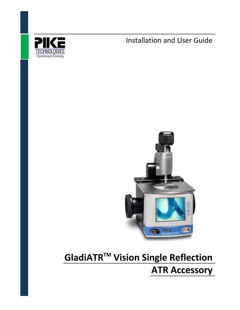
Installation and User Guide<strong>GladiATR</strong> TM <strong>Vision</strong> Single ReflectionATR Accessory
The information in this publication is provided for reference only. Allinformation contained in this publication is believed to be correct andcomplete. <strong>PIKE</strong> <strong>Technologies</strong>, Inc. shall not be liable for errors contained hereinnor for incidental or consequential damages in connection with the furnishing,performance, or use of this material. All product specifications, as well as theinformation contained in this publication, are subject to change without notice.This publication may contain or reference information and products protectedby copyrights or patents and does not convey any license under the patentrights of <strong>PIKE</strong> <strong>Technologies</strong>, Inc. nor the rights of others. <strong>PIKE</strong> <strong>Technologies</strong>, Inc.does not assume any liability arising out of any infringements of patents orother rights of third parties.This document contains confidential or proprietary information of <strong>PIKE</strong><strong>Technologies</strong>, Inc. Neither this document nor the information herein is to bereproduced, distributed, used or disclosed, either in whole or in part, except asspecifically authorized by <strong>PIKE</strong> <strong>Technologies</strong>, Inc.<strong>PIKE</strong> <strong>Technologies</strong>, Inc. makes no warranty of any kind with regard to thismaterial including, but not limited to, the implied warranties of merchantabilityand fitness for a particular purpose.Copyright 1991-2015 by <strong>PIKE</strong> <strong>Technologies</strong>, Inc., Madison, WI 53719. Printed inthe United States of America. All world rights reserved. No part of thispublication may be stored in a retrieval system, transmitted, or reproduced inany way, including but not limited to, photocopy, photograph, magnetic orother record, without the prior written permission of <strong>PIKE</strong> <strong>Technologies</strong>, Inc.Address Comments to:<strong>PIKE</strong> <strong>Technologies</strong>, Inc.6125 Cottonwood DriveMadison, WI 53719Phone (608) 274-2721Fax (608) 274-0103E-mailinfo@piketech.comWeb Site www.piketech.comJan. 1, 2015
ContentsIntroduction 1<strong>GladiATR</strong> Assembly View 2Unpacking Your Accessory 3Packing List 3Assembly 5Installation 7Accessory Installation 7Software Installation 8Installing Videology Image Capture Software 8Interfacing the <strong>GladiATR</strong> <strong>Vision</strong> 8Installing IC 2.2 Image Capturing Software (BNC) 9Accessory Alignment 10Adjusting Camera Focus 11Performance Verification 12Sampling Procedures 13Sample Analysis with High-Pressure Clamp 14Pressure Clamp Tip Attachments 15Configuration for Liquid Sampling 16Configuration for Solid Sampling 18Configuration for Powder Sampling 19Crystal Cleaning 19Effects of Temperature 19ATR Spectra 20ATR Correction 21Useful Equations 22Solid Samples 22Crystal ATR Materials 22Diamond 22Germanium 22Precautions 23Mirrors 23SAFETY 23Environmental Ratings 24Specifications 24Power Supply Symbol Definitions 25Replacement Parts and Options 26
Introduction<strong>GladiATR</strong> <strong>Vision</strong> – Diamond ATR with Sample ViewThe <strong>GladiATR</strong> <strong>Vision</strong> is a novel sampling tool which couples small area infrared analysis withsimultaneous viewing. Samples are placed face down and positioned on the diamond crystal while itsimage is projected in real-time on the LCD screen. Finding and optimizing the sample placement forspecific analysis areas is easy and fast. Analysis of thick or non-transparent samples is no problembecause viewing is through the diamond crystal.The <strong>GladiATR</strong> <strong>Vision</strong> accessory utilizes an innovative optical design with IR beam and visible opticalimage converging at the sample position – ensuring that “What you see is what you sample!” The 110Xmagnification of the sample image enables the positioning of even relatively small samples into thecenter of the diamond crystal for optimized analysis. Analysis of samples as small as 50 microns in size ispossible with the <strong>GladiATR</strong> <strong>Vision</strong> accessory.The <strong>GladiATR</strong> <strong>Vision</strong> optical design is all reflective, preserving the full spectral range inherent todiamond. For standard mid-IR FTIR spectrometers, the spectral range available with the <strong>GladiATR</strong> <strong>Vision</strong>will be 4000 – 400 cm -1 . For FTIR spectrometers equipped with far-IR optics, the spectral range isextended to less than 50 cm -1 .Utilizing the diamond crystal of the <strong>GladiATR</strong> <strong>Vision</strong> with its 45° angle of incidence the depth ofpenetration of the IR beam for most organic samples is about 2 microns at 1000 cm -1 . This small depthof penetration enables most liquid, solid, polymer, gels or paste samples to be measured without anysample preparation – greatly saving analysis time compared to conventional transmission samplingtechniques. Solid samples are placed upon the diamond ATR crystal, pressure is applied via the clickstoppressure clamp and the spectrum is collected. Liquid samples are simply applied to the ATR crystaland the spectrum is collected. If the liquid sample is volatile the optional Liquids Retainer should beattached to the crystal plate and the Volatiles Cover is placed over the sample before the spectrum iscollected.Options for the <strong>GladiATR</strong> <strong>Vision</strong> include a Ge crystal plate (non-viewing) for high refractive indexsamples, a specular reflectance plate (non-viewing) for reflectance analysis of coatings on reflectivesubstrates and a Flow-Through Attachment.The <strong>GladiATR</strong> <strong>Vision</strong> offers optional resistively heated crystal plates with maximum temperatureoperation to 210 °C (diamond) and 130 °C (germanium, non-viewing.) These heated crystal plates areoperated via <strong>PIKE</strong> <strong>Technologies</strong> temperature controllers – digital/PC or digital versions.The <strong>GladiATR</strong> <strong>Vision</strong> is available in configurations to fit most FTIR spectrometers.PN 350-026019-04 Page | 1
Packing List (Continued)<strong>GladiATR</strong> <strong>Vision</strong> Crystal Plate OptionsDescriptionPart NumberDiamond <strong>Vision</strong> Crystal Plate 026-2102Ge Crystal Plate (non-viewing) 026-2050Specular Reflection Plate (non-viewing) 026-2200Specular Reflection Plate (viewing) 026-2202Heated Diamond Crystal Plate, 210 °C, <strong>Vision</strong> 026-4101Heated Ge Crystal Plate, 130 °C (non-viewing) 026-4050The <strong>GladiATR</strong> base optics assembly has a crystal plate and the purge tubes attached. Some base opticsassemblies may appear different due to specific baseplate mountings for your FTIR.The pressure clamp, pressure tips, purge tubing kit and wrench set are packed separately in the carryingcase. The purge tubing kit is not needed with most FTIR models. The swivel tip is attached to thepressure clamp assembly.PN 350-026019-04 Page | 4
Assembly1. Attach the <strong>GladiATR</strong> base optics to its baseplate. This is done by securing the optics base with twoscrews, one on each side (Figure2).Figure 2. Location of screws securing the optics base2. Install the ATR crystal plate. For proper orientation the serial number is situated at the 1 o’clockposition (Figure 3). The support bar is not visible when using the Ge ATR plate. Installing the ATRcrystal plate improperly will result in no or very low throughput energy through the accessory.When installing the 210 °C heated diamond plate and the heated Ge plate align the electrical pins onthe plate to the connector pad located on the top of the base optics and continue to follow theinstructions for the standard diamond plate described in step 2.Serial numberat 1 o’clock positionFigure 3. Top view of crystal plate properly seated on the accessoryFront of accessoryPN 350-026019-04 Page | 5
3. Place the clamp over the dowel pins located on the top of the accessory. Secure using the two largehex nuts (Figure 4). Instructions for clamp operation are detailed on page 14 of this manual.4. Complete accessory assembly by pressing the stainless steel top plate over the crystal ATR plate(Figure 5).Hex NutHex NutStainless SteelTop PlateFigure 4. Proper placement of clamp on thetop of the accessoryFigure 5. Proper placement of top plate overthe crystal ATR plate5. If purging is required, press the blue tubing included with the <strong>GladiATR</strong> into the quick-disconnectport located on the front of the base optics. To remove the tubing, press the black ring of theopening in and pull the tubing out.6. For heated configurations, connect the heater cable between the connector (located on the lowerleft side of the front panel) and the temperature controller.7. Connect the video power cable to the right lower front of the base optics.8. Connect the USB or BNC cable, if the BNC video capture option was purchased, to the lower rightfront of the base optics and to the computer (USB version) or frame grabber box (BNC version).PN 350-026019-04 Page | 6
InstallationThe <strong>GladiATR</strong> <strong>Vision</strong> accessory has been aligned and tested in the <strong>PIKE</strong> <strong>Technologies</strong> facility on yourmodel FTIR spectrometer to ensure that it performs to specifications. However, some variation in opticalalignment can occur from spectrometer to spectrometer. To allow for this difference, there areadjustable alignment screws within the <strong>GladiATR</strong> <strong>Vision</strong> base optics assembly for fine-tuning once theaccessory is installed in the spectrometer. The following is the procedure for accessory installation andfinal alignment.Accessory Installation1. Set your FTIR spectrometer to collect data at 4 cm -1 spectral resolution (including the FTIR J-stop).2. The <strong>GladiATR</strong> <strong>Vision</strong> accessory fits into the sample compartment of the FTIR spectrometer. Your<strong>GladiATR</strong> <strong>Vision</strong> is provided with the appropriate sample compartment baseplate for the model FTIRinstrument you specified. Before inserting the accessory in the sample compartment, ensure thatyour spectrometer is aligned. If the instrument is not aligned, maximize the interferogram signal(the IR energy throughput) of your FTIR spectrometer. This should be performed by following themanufacturer’s instructions.3. Fasten the accessory directly into the FTIR sample compartment or onto the FTIR samplecompartment baseplate using the 2 screws located one on each side of the <strong>GladiATR</strong> <strong>Vision</strong> baseoptics (Figure 1). In order to locate the accessory in the correct position, simply place the entireaccessory into the FTIR sample compartment with the <strong>GladiATR</strong> <strong>Vision</strong> label facing the front and lineup the baseplate provided with the holes/pins in your model FTIR spectrometer.4. Tighten the mounting screws to firmly position the accessory baseplate onto the FTIR samplecompartment baseplate.5. Mount the pressure clamp onto the back side of the accessory using the two alignment dowel pinson top of the <strong>GladiATR</strong> <strong>Vision</strong> base and fasten using the two hex-head screws into the clamp frame.6. Install the IC 2.2 software and cables for the BNC version of the <strong>GladiATR</strong> <strong>Vision</strong> or Videologysoftware for the USB configuration. Follow instructions in the next section for your specificaccessory model.PN 350-026019-04 Page | 7
Software InstallationThe <strong>GladiATR</strong> <strong>Vision</strong> may be configured for either a USB bus, most often, or a BNC connector. If you havethe USB bus, follow the Installing Videology Image Capture Software instructions. For the BNCconnector, follow the Installing IC 2.2 Image Capturing Software instructions.Installing Videology Image Capture Software (USB)Minimum system requirements for the Videology software are a PC with a USB 2.0 compatible port,Windows XP (service pack 2 preferred) or Windows 7, Pentium 4 2.0 GHz, hard drive speed 5,400 RPM,and 128 MB of RAM.Videology CD will automatically launch the installation wizard. If this does not occur, select autorun.exefile located on the software CD. Be sure the USB cable is NOT connected to the computer USB port at thistime. You will be prompted to connect the USB cable from the <strong>Vision</strong> to the computer USB port duringinstallation. After the USB connection wait a few moments for your computer to recognize the hardware.Additional installation information is located in the Videology manual found on the Videology CD.Interfacing with the <strong>GladiATR</strong> <strong>Vision</strong>1. With the LCD screen powered on, open the Videology Viewer software. The camera image should beshown on the computer screen. If the image is not shown, select Advanced Option found under theOptions drop down menu. Check Isochronous Pipe, which determines how the streaming video issent through the USB bus. Under the Options drop down menu, select camera settings. The VideoCapture Filter Properties should be set to CVBS as the source and NTSC_M as the format.PN 350-026019-04 Page | 8
2. Prior to capturing images set the folder where images will be saved. From the file menu, select SetSnap Image Folder and assign a folder. An image is saved by selecting Take Snapshot in the Filemenu.The <strong>GladiATR</strong> <strong>Vision</strong> is now ready for alignment.Installing IC 2.2 Image Capturing Software (BNC)IC 2.2 is an optional component for the <strong>GladiATR</strong> <strong>Vision</strong> that allows the LCD image to be captured andsaved as a .jpg file. To capture saved images, the computer requirements are PC or laptop with PIII/800MHz/256 MB or higher, a USB 2.2 interface, and Windows XP/SP2, Windows Vista (32 or 64 bit), orWindows 7 as the operating system.1. Prior to installing the software, connect the BNC-to-composite video cable to the BNC jack locatedon the front of the <strong>GladiATR</strong> <strong>Vision</strong> and to the Imaging Source box. Also, connect the USB cable tothe USB 2.0 on the computer and to the Imaging Source box. Then, power up the LCD screen.2. Follow the Getting Started instructions provided by Image Sourcing for the Video-to-USB ConverterDFG/USB2-It.3. With the LCD screen powered on, open the IC 2.2 software. Select the DFG/USB2-It drive. Thefollowing settings should be shown on the device bar. With the exception of the FPS (frames persecond), which is a default value depending on the configuration of the computer, the settingsshould mimic those shown below - make sure NTSC_M is selected.4. The LCD image transferred to the computer screen is live. If the image is a still frame, go to thedevice menu and select “live” (or press ctrl-l). Image color saturation, brightness, contrast, andsharpness may be tuned to preference through “properties” found in the device drop-down menu.5. Images are easily saved by selecting “save image” in the drop-down “capture” menu in either .jpg or.bmp format. The snap image option in the capture menu will cause the image on the computer tobecome still framed; the image on the <strong>GladiATR</strong> <strong>Vision</strong> screen remains live. To return to a live imageon the computer screen, select “live” in the device menu or press ctrl-l.The <strong>GladiATR</strong> <strong>Vision</strong> accessory is now ready for optical alignment.PN 350-026019-04 Page | 9
Accessory AlignmentThe <strong>GladiATR</strong> <strong>Vision</strong> accessory may not require any alignment when installed - see page 12 for minimumvalues. However, should you choose to fine-tune the accessory, follow these steps:1. Make sure the LCD display is turned off and the power input is removed. Remove the front panel ofthe <strong>GladiATR</strong> <strong>Vision</strong> accessory by loosening the 4 hex head retaining screws, two on each side of thefront panel. Pull the front panel forward to release from the screws and place it in a secure restingplace on top of the crystal plate on top of the <strong>GladiATR</strong> <strong>Vision</strong> base optics (position the High-Pressure Clamp in the back rotated position to make room for the front panel). Do not undo theelectrical wires connecting the camera and the front panel.2. Display the live interferogram of the FTIR spectrometer and adjust the input optic, the crystal focusand the relay mirror. To do this, turn the individual screws one at a time slightly clockwise and checkthe signal. If it increases, continue until the maximum signal is obtained. If it decreases, turn thescrew counterclockwise to get the highest possible reading. Follow the order shown in thealignment image, first adjusting the input optic screw to obtain the maximum signal, then go tothe 2 sets of crystal focus screws and optimize the interferogram signal.Crystal FocusInput OpticsRelay MirrorDo not adjustFigure 6. Alignment of the <strong>GladiATR</strong> <strong>Vision</strong>PN 350-026019-04 Page | 10
3. Finally, adjust the relay mirror screws to optimize the interferogram signal.4. Repeat the entire procedure 2-3 times to fine-tune the accessory. This is an initial (one-time)alignment procedure which optimizes the <strong>GladiATR</strong> <strong>Vision</strong> to work with an individual optical bench.Once completed, the alignment does not have to be repeated, unless the accessory adjustmentshave been moved or it has been placed in a different FTIR instrument.You are now ready to verify the <strong>GladiATR</strong> <strong>Vision</strong> optical throughput performance.Adjusting Camera FocusThe camera was focused prior to leaving our facility. You may choose to adjust as clamp pressure mayaffect the focusing distance causing a less sharp image. To adjust the camera focus, loosen four hexscrews located on the sides of the front panel, which secure the front accessory panel with the LCDscreen. Remove the front panel to access the focusing thumb wheel. To adjust the camera focus, loosenthe button head screw located underneath the focus thumb wheel. Monitor the image quality whileturning the thumb wheel to the left and right. Only small left or right movements should be required.Once the optimal focus has been found, tighten the button head screw and secure the front panel withthe 4 hex screws located on the front panel sides.Camera Focus AdjustmentThumb-WheelButton Head ScrewFigure 7. Camera focus adjustmentPN 350-026019-04 Page | 11
Performance Verification1. With the accessory removed from the sample compartment, collect an open beam backgroundspectrum.2. Place the aligned <strong>GladiATR</strong> <strong>Vision</strong> accessory into the instrument.3. Collect a transmission spectrum using the same collection parameters as used to collect thebackground spectrum. This resulting spectrum is termed a throughput spectrum and measures theIR spectrum of the <strong>GladiATR</strong> <strong>Vision</strong> accessory.4. Place a cursor on the throughput spectrum at 1000 cm -1 and record the value in % transmission.NOTE: Each of the different crystals (diamond or Ge) will have different looking spectra. An examplethroughput spectrum for diamond is shown below. Diamond has strong, broad phonon absorbancebands in the region of 2100 cm -1 . This is normal and will ratio out well in resulting spectra.<strong>GladiATR</strong> ThroughputThe following are the % transmission values the accessory should achieve with different crystalconfigurations at 1000 cm -1 .Diamond Crystal Plate: Greater than 14%TGe Crystal Plate: Greater than 14%TPN 350-026019-04 Page | 12
If your accessory does not meet this minimum transmission level, please contact <strong>PIKE</strong> <strong>Technologies</strong>.Before making this call, please record the serial number located on the label on the back of the <strong>GladiATR</strong><strong>Vision</strong> base optics assembly.NOTE: IR throughput performance of your accessory may decrease slowly over time as the ATR crystalplate surface is exposed to normal wear from cleaning the ATR surface. Please Contact <strong>PIKE</strong> <strong>Technologies</strong>for information about <strong>GladiATR</strong> <strong>Vision</strong> service when transmission throughput drops below a usable level.Sampling ProceduresCollect the background spectrum with the accessory in the sample compartment. Make sure the ATRcrystal is clean and free of any residues. Once completed, place the sample on the crystal surface (applythe clamp if solid) and collect sample spectrum. A single crystal plate design is used for all types ofsamples (liquids, pastes, powders, soft pliable films and solids).The sample must be in intimate contact with the ATR crystal surface for the evanescent wave to providean ATR signal. Note that the Ge crystal used in the accessory is made of materials considerably softerthan diamond. Ge can be scratched if care is not used to remove samples. Scratches on the surface ofthe crystal will result in a reduction in the throughput of the accessory. Remove the sample gently witha non-abrasive cotton tissue and clean with solvent. The crystal plate should be cleaned with anappropriate mild solvent, such as isopropyl alcohol or a stronger solvent, such as acetone. Cotton swabsare highly recommended for ease of cleaning without scratching the ATR crystal surface.Sometimes “carry over” may occur from one sample to another due to incomplete cleaning of a priorsample from the face of the crystal. This effect may be minimized by collecting a new backgroundspectrum before each sample spectrum.Samples should not be left in contact with the crystal for an extended period of time since some samplesmay degrade the crystal material and discoloration of the metal plate can occur. Once the measurementhas been made, remove the sample from the crystal and clean the surface of the crystal and thesurrounding plate area with a suitable solvent. Note that the High-Pressure Clamp for the <strong>GladiATR</strong> canbe swung back to give more access to the ATR crystal area by loosening the smaller clamp knob.PN 350-026019-04 Page | 13
Sample Analysis with High-Pressure Clamp1. Loosen the small, arm-securing knob.2. Raise the clamp arm up and place your sample on the diamond crystal. Some friction during the armmovement is normal as it prevents its accidental drop and crystal damage.3. Lower the arm, slightly push the arm-securing knob down and tighten it all the way (please do notuse any tools in this process as finger pressure alone is sufficient).4. Turn the large clamp knob clockwise to compress the sample. Two “clicks” indicate that theoptimum pressure has been achieved.5. After the measurement is completed, release the main knob first and the small knob second if thearm needs to be raised. Please keep in mind that the small knob is spring loaded and it needs to bepressed in for the screw to engage again.Main pressure tower knobSmall, arm-securing knobCAUTION: <strong>GladiATR</strong> crystal damaged by excessive pressure cannot be covered by the warranty.Caution is required when using the High-Pressure Clamps with the Ge ATR plate. The diamond crystalplate is very rugged. This crystal will withstand higher pressures than traditional IR materials, but it stillmay be damaged by an excessive force. For this reason, do not exceed the pressure originally set by thefactory on the High-Pressure Clamps. The applied pressure is a function of the size of the pressure tip forlarge samples or the size of the sample for small samples.PN 350-026019-04 Page | 14
Pressure Clamp Tip AttachmentsThe success of an ATR measurement depends upon the quality of the contact between the sample andthe crystal. Since there is an infinite number of sample shapes and types, a single configuration of thesample press tip may not be adequate. For this reason, the <strong>GladiATR</strong> pressure clamp is designed toaccept three different tip attachments, providing the best possible configuration for any given sampletype.The accessory is shipped with the swivel tip attached to the pressure clamp ordered with the <strong>GladiATR</strong>accessory. This tip features an end cap mounted onto a small ball joint. Such design allows the pressuretip to move and adjust its position to the shape of the sample and maintain the sample position parallelto the crystal surface. This tip allows for better positioning and optimal contact of thin materials withthe ATR crystal surface. The swivel tip is used with irregularly shaped samples, films, semi-rigid polymers(e.g. credit card like materials).The flat tip attachment is a flat-tipped cone and it is used when analyzing thin films, fibers, smallparticles, rubber samples and other elastic polymers. The flat tip may also be used for powderedsamples.The concave tip was developed specifically to work with granules, large beads and polymer pellets. Thetip features a concaved surface which prevents the sample from escaping from underneath the press. Italso forces the spherical samples to stay in the center of the crystal, assuring maximum IR signalstrength. Do not use the concave tip for powdered samples or samples which do not completely protectthe concave edges of the steel tip from pressing against the ATR crystal - this will damage the ATRcrystal.PN 350-026019-04 Page | 15
Configuration for Liquid SamplingThe crystal plate assembly of the <strong>GladiATR</strong> accessory features a round plate design with a 3.0 mmdiameter ATR crystal sampling area located in the center of the plate. For liquid sampling, a droplet ofthe sample is placed onto the ATR crystal.For volatile liquids, the optional Liquids Retainer with Volatiles Cover reduces the amount ofevaporation of the sample on the surface of the crystal. To use, place the retainer disk over the ATRcrystal. Place the U-shaped bridge over the retainer disk. Apply pressure to the U-shaped bridge usingthe pressure clamp. Fill the reservoir of the Liquids Retainer with the volatile liquid. Slide the VolatilesCover between the retainer disk and the U-shaped bridge (Figure 10).U-ShapedBridgeVolatiles CoverLiquids RetainerFigure 10. Proper placement of a Liquids Retainer and Volatiles Cover on the <strong>GladiATR</strong> accessoryFor continuous sample monitoring, or for applications where the sample needs to be completelyenclosed for safety or reactivity reasons, an optional Flow-Through Attachment is available. To use,place the Flow-Through Attachment over the ATR crystal. Apply the clamp to the top of the Flow-Through Attachment, which creates a seal between the O-ring located on the underneath side of theFlow-Through Attachment and the ATR crystal plate (Figure 11). Using the Luer-Loc fitting, load thesample by connecting a syringe or a flow line.Figure 11. <strong>GladiATR</strong> with Flow-Through AttachmentPN 350-026019-04 Page | 16
One minute, 4 cm -1 resolution spectra of a dilute detergent solution and distilled water were collectedusing the <strong>GladiATR</strong> <strong>Vision</strong> with diamond crystal. These samples were applied directly onto the <strong>GladiATR</strong>diamond ATR crystal for analysis.The red spectrum is the detergent solution and the blue spectrum is that for distilled water. A spectralsubtraction can be applied to obtain the spectrum of the detergent component. This is shown in the redspectrum on the right, and the result will represent the detergent contribution of the liquid sample.Detergent SolutionDistilled H 2 0Subtraction Result; Detergent SolutionPN 350-026019-04 Page | 17
Configuration for Solid SamplingFor measurements of soft pliable films and selected solid samples, the sample is placed onto the surfaceof the crystal. Since the ATR effect only takes place very close to the surface of the crystal, an intimatecontact has to be made by the sample on the ATR crystal surface. This is achieved by using the pressureclamp ordered with your <strong>GladiATR</strong> system. With the sample in place on the crystal, lower the pressuretip so that it is in contact with the sample. You can continue to turn the pressure knob and increasepressure to a desired level to obtain a spectrum. However, in most cases, it is recommended to applythe maximum pressure allowed to ensure the best contact and highest sampling sensitivity. The forceapplied by the High-Pressure Clamps is factory set to 40 pounds. The applied pressure is then a functionof the size of the pressure tip for large samples or the size of the sample for small samples. For example,40 pounds of force upon a sample which completely covers the crystal will generate 6,789 psi whereas40 pounds of force upon a 1.0 mm diameter flat sample will generate 32,858 psi. The High-PressureClamp has a slip clutch mechanism to avoid exceeding 40 pounds of force.CAUTION: Care must be used in operating the pressure clamps, since for small hard samples themaximum pressure may be exceeded.For the analysis of solid samples the pressure clamp of the <strong>GladiATR</strong> is required. The sample is placedface down onto the diamond crystal and force is applied to make intimate contact onto the ATR crystal.The <strong>GladiATR</strong> accessory enables us to position the sample to a feature area to ensure that the spectrumcollected is taken from the desired location on the sample. The spectrum below is collected from theprint area on paper. For this analysis pressure was applied to the sample using the swivel tip. Theacquisition time was one minute and the spectral resolution was set to four wavenumber.PN 350-026019-04 Page | 18
Configuration for Powder SamplingMost powders may be analyzed with an ATR accessory. Note that since the ATR effect requiresthe sample to be in intimate contact with the crystal, this method is most effective whenanalyzing soft powders.Crystal CleaningThe solvent used for cleaning your crystal is dependent on the sample that has been analyzed. In allcases it is best to attempt to clean the crystal with the mildest solvent possible. For most cases, thepreferred solvent is isopropyl alcohol. If a stronger solvent is required, acetone may be used. In verystubborn cases dimethylformamide may be used. In all cases when using solvents, inspect the materialssafety data sheet associated with the solvent you are using and comply with any recommended handlingprocedures. Apply the solvent to the crystal with a cotton swab and gently remove using the cottonswab or non-abrasive wipe. Repeat this procedure until all traces of the sample have been removed.Under no circumstances should the softer crystal materials (Ge) be rubbed with paper products such as“Kleenex” or “Kim wipes”. Many paper products are abrasive and could cause scratching of the softercrystal surfaces.Effects of TemperatureThe <strong>PIKE</strong> <strong>Technologies</strong> <strong>GladiATR</strong> <strong>Vision</strong> utilizes brazing and bonding technology to seal thecrystal to its mount. This sealing mechanism allows some flexibility and hot samples may beplaced on the crystal without damaging the crystal or seal. However, it is recommended thatthe temperature difference between the sample and the crystal be not more than 30 °C.PN 350-026019-04 Page | 19
ATR SpectraATR spectra are similar to transmission spectra. A careful comparison of ATR spectra and transmissionspectra reveals that the intensities of the spectral features in an ATR spectrum are of lower absorbancethan the corresponding features in a transmission spectrum and especially in the high wavenumber(short wavelength) region of the spectrum. The intensity of the ATR spectrum is related to thepenetration depth of the evanescent wave into the sample. This depth is dependent on the refractiveindex of the crystal and the sample, and upon the wavelength of the IR radiation.The relatively thin depth of penetration of the IR beam into the sample creates the main benefit of ATRsampling. This is in contrast to traditional FT-IR sampling by transmission where the sample must bediluted with IR transparent salt, pressed into a pellet or pressed to a thin film, prior to analysis toprevent totally absorbing IR bands.A comparison of transmission vs. ATR sampling result for a thick polymer sample is shown below wherethe sample is too thick for high quality transmission analysis (shown in the lower spectrum). Intransmission spectroscopy, the IR beam passes through the sample and the effective pathlength isdetermined by the thickness of the sample and its orientation to the directional plane of the IR beam.Clearly in the example shown below the sample is too thick for transmission analysis because most ofthe IR bands are totally absorbing.However, simply placing the thick sample on the ATR crystal and applying pressure generates a highquality spectral result (upper red spectrum) - identified by library search as a polybutyleneterephthalate. The total analysis time for the thick polymer by ATR was less than one minute.PN 350-026019-04 Page | 20
ATR CorrectionIf an ATR spectrum representative of a transmission spectrum is desired, the ATR spectrum must beprocessed with the ATR correction program available in your instrument software. An example of theeffect of this correction on a spectrum is shown in the following example for polystyrene. The middlespectrum is the original ATR spectrum of polystyrene. The lower spectrum is the transmission spectrumof polystyrene. Clearly the IR bands around 3000 cm -1 in the ATR spectrum are weaker relative to the IRbands at longer wavelength.However, in the upper red spectrum after ATR correction, the relative IR band intensities are very similarto those from the polystyrene run by transmission.Polystyrene, ATR CorrectedPolystyrene, ATR, Original SpectrumPolystyrene, 1.5 mil. film, by transmissionPN 350-026019-04 Page | 21
Useful EquationsThe depth of penetration gives us a relative measure of the intensity of the resulting spectrum and isexpressed by the following equation:λd p =22π( n 1 sss 2 2θ − n 2 ) 1/2Where λ is the wavelength of light, n 1 is the refractive index of the crystal, n 2 is the refractive index ofthe sample and θ is the effective angle of incidence.Depth of penetration in microns as a function of crystal material is shown in the table below. Thepenetration depth is calculated for a sample with a refractive index of 1.5 at 1000 cm -1 .Crystal ATR MaterialsMaterial RI d p (µ) @1000 cm -1 pH Range Long Wave CutoffDiamond 2.4 2.0 1-14 10 cm -1Ge 4.0 0.66 1-14 450 cm -1DiamondDiamond is one of the most rugged optical materials. It can be used for analysis of a wide range ofsamples, including acids, bases, and oxidizing agents. Diamond is also scratch and abrasion resistant. Itsdisadvantage is the intrinsic absorption from approximately 2300 to 1800 cm -1 which limits itsusefulness in this region for detecting extremely small absorbance across this spectral range.GermaniumGermanium has been used extensively in the past as a higher refractive index material for samples thatproduce strong absorptions such as rubber O-rings. The crystal is also used when analyzing samples thathave a high refractive index, such as in passivation studies on silicon.PN 350-026019-04 Page | 22
PrecautionsMirrorsIn order to provide the maximum reflectivity in the infrared, with the minimum spectral interferences,the mirrors used in this device are uncoated (bare) aluminum. Normally, these mirrors will not requirecleaning, since they are contained within the housing of the accessory. If they do need cleaning, pleasecontact <strong>PIKE</strong> for recommendations. Under no circumstances must the mirrors be rubbed with paperproducts since this will produce scratching of the mirror surface.SAFETYCaution should be used when handling and using ATR crystals since some of the materials can behazardous. If the crystal is broken or pulverized, the dust may be harmful by inhalation, ingestion or skinabsorption.Protection provided by the equipment may be impaired if the equipment is used with accessories notprovided or recommended by the manufacturer, or is used in a manner not specified by themanufacturer.Periodically inspect the External Power Supply interconnect cord and other parts for damage. If anydamage is observed, do not use the equipment and contact <strong>PIKE</strong> <strong>Technologies</strong> for replacement parts.Do not position the equipment in a space where it is difficult to disconnect the power cord at the frontof the equipment.PN 350-026019-04 Page | 23
Environmental RatingsInstallation Category IIPollution Degree 2Altitude LimitUseAmbient TemperatureHumidity(Transient over-voltage)(Temporary conductivity caused by condensation)2,000 meters“Indoor” use40 °C max80 % RH non-condensingSpecificationsATR Crystal ChoicesCrystal Plate MountingCrystal TypeDiamond setCrystal Plate MountsAngle of IncidenceCrystal Dimensions, SurfaceOpticsPressure DeviceMaximum PressureSample AccessSpectral Range, DiamondViewing OptionMagnificationView AreaOptional Image SaveViewing ModeInput VoltageOperating VoltageWattageExternal Power SupplySpecular Reflection OptionPurgeAccessory Dimensions(W x D x H)FTIR CompatibilityDiamond, germanium (non-viewing)User changeable platesMonolithicBrazedStainless steel45°, nominal3.0 mm diameterAll reflectiveRotating, continuously variable pressure; click stop at maximum30,000 psi80 mm, ATR crystal to pressure mount4000 to 10 cm -1 (IR optics dependent)Integrated 4” LCD110X magnification770 x 590 micronsUSB image captureThrough diamond crystal90-264 V, auto setting, external power supply12 VDC18 watts max100-240 VAC, 50/60 Hz, 0.6 Amps max.Optional, 45° nominal angle of incidencePurge tubes and purge line connector included140 x 225 x 340 mm (excludes FTIR baseplate and mount)Most, specify model and typePN 350-026019-04 Page | 24
Power Supply Symbol DefinitionsDC - Direct CurrentAC - Alternating CurrentEquipment protected throughout by Double or Reinforced InsulationLabel Description LocationCE marking indicates the accessory complies with theessential requirements of the relevant Europeanhealth, safety and environmental protectionlegislations.The RoHS symbol indicates this product is free fromRoHS prohibited elements and compounds (Pb, Cd,Hg, Hex-Cr, PBB, and PBDE).This symbol is locatedon the backside of the<strong>GladiATR</strong> <strong>Vision</strong>.This symbol is locatedon the backside of the<strong>GladiATR</strong> <strong>Vision</strong>.The crossed out wheeled bin is a clear reminder thatthe product must not be disposed with householdwaste. It is the responsibility of the buyer to discardthe product in accordance with federal, regional, andlocal environmental regulations.This symbol is locatedon the backside of the<strong>GladiATR</strong> <strong>Vision</strong>.PN 350-026019-04 Page | 25
Replacement Parts and OptionsThe following parts and options may be ordered for the <strong>GladiATR</strong> <strong>Vision</strong> accessory:<strong>GladiATR</strong> <strong>Vision</strong> Crystal PlatesPart Number Description026-2102 Diamond <strong>Vision</strong> Crystal Plate026-2050 Ge Crystal Plate (non-viewing)026-2200 Specular Reflection Plate (non-viewing)026-4101 Heated Diamond Crystal Plate, 210 °C, <strong>Vision</strong>026-4050 Heated Ge Crystal Plate, 130 °C (non-viewing)<strong>GladiATR</strong> <strong>Vision</strong> Image Capture OptionPart Number Description026-3510 USB Interface Adapter and Software for BNC model of <strong>GladiATR</strong> <strong>Vision</strong>Temperature ControllersPart Number Description076-1220 Digital Temperature Control Module (210 °C)076-1420 Digital Temperature Control Module, PC Control (210 °C)Pressure ClampPart Number Description026-3020 High-Pressure Clamp076-6026 Digital Force Adapter for High-Pressure ClampOther AttachmentsPart Number Description026-5012 Flow-Through Attachment026-5013 Liquids Retainer and Volatiles Cover Set026-5010 Liquids Retainer for Performance Plates026-3051 Volatiles Cover for Performance Plates025-3095 Flat Tip025-3093 Swivel Tip025-3092 Concave TipPN 350-026019-04 Page | 26
6125 Cottonwood Drive · Madison, WI 53719-5120 · (608) 274-2721 (TEL) · (608) 274-0103 (FAX)info@piketech.com · www.piketech.com