Boeing AERO Angle of Attack - Leonardo
Boeing AERO Angle of Attack - Leonardo
Boeing AERO Angle of Attack - Leonardo

You also want an ePaper? Increase the reach of your titles
YUMPU automatically turns print PDFs into web optimized ePapers that Google loves.
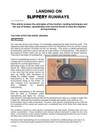
estimated based on a measuring devicemounted somewhere on the airplane.Any such device has inherent errorsthat must be addressed.Wherever the device is located, itis measuring the flow angle in its ownlocal vicinity, not at the wing. Stallwarning devices have been mounted onthe wing, but most modern commercialjet airplanes have movable leading edgesthat would interfere with such an installation.Most have the sensor locatedon the fuselage, far ahead <strong>of</strong> the wing,reducing the effect <strong>of</strong> changes in liftand configuration. Nearer to the nose<strong>of</strong> the airplane, the airflow is relativelyclean and the boundary layer is thin,minimizing the required probe height.Even at the nose, many factors canaffect the relationship between thelocal AOA and true wing AOA (fig. 9).The angle <strong>of</strong> airflow around the noseis not the same as at the wing.Also, the sensitivity to changes inAOA is greater, so a 1-deg changein true wing AOA causes a local flowchange at the nose <strong>of</strong> 1.5 to 2 deg. Thetrailing-edge flap position has an influenceon a typical AOA sensor calibration,as has landing gear position (inparticular, that <strong>of</strong> the nose landing geardoors). Mach number affects the flowaround the nose and therefore changesthe sensor calibration.Pitching the airplane can cause erroneousreadings at the sensor. While thenose is pitching up (as in a turn), thelocal flow angle is reduced, causingthe reading to be too low. Although thesensors are placed to minimize theeffect <strong>of</strong> sideslip, it is not eliminatedand can be quite significant at sideslipangles that may occur on short finalapproaches or with an engine out.Even variations in the contour <strong>of</strong> theskin near the sensor can subtly affectthe local flow angle. Many <strong>of</strong> thesedesign challenges also affect pitot andstatic port installation and accuracy.The sensor itself has potentialfor error. The combination <strong>of</strong> installationerror, zero bias, and aerodynamicinaccuracy can total 0.5 deg or more.Contamination or damage can alsoaffect the sensor’s accuracy.9FIGUREAOA MEASUREMENT ERRORSMach numberMachnumber0.4 deg0.4 degAOA vane AOA vaneAOA body AOA bodyGear positionAOA vane AOA vane Gear down0.5 deg0.5 degGear upAOA body AOA bodyPitch rateAOA vane AOA vanePitch rateGroundeffect0.3 deg0.5 degFree airAOA body AOA bodyFor the most part, the effectsdiscussed above can be compensatedfor and, depending on the airplane,many have been. It should be noted,however, that each correction has itsown inherent uncertainty and can alsocause erroneous readings if the inputdata is incorrect.In the philosophy <strong>of</strong> “keep it simple,”the fewer dependencies on otherdata, the more robust the AOA system willbe. For example, Mach number affectsthe sensor calibration. While this relationshipcould be compensated for, thiswould make the sensor output dependenton good Mach information. If theairspeed data were inaccurate, thecalculated Mach number and thereforethe calibrated AOA reading would beincorrect. This would affect the usefulness<strong>of</strong> AOA in the event <strong>of</strong> an airspeedsystem failure. Note that because theFlap positionFlappositionSideslipSideslipGround effectsensors are located near the nose andthe air data probes, certain conditions,such as radome damage or loss, maycause erroneous measurement <strong>of</strong> AOAas well as airspeed.AOA INDICATIONS AND FLIGHT4 CREW PROCEDURES IN CURRENTBOEING PRODUCTION MODELSAOA is most useful to the flight crewat high angles <strong>of</strong> attack to show themargin to stall or stall warning. Allindications driven by AOA—stick shaker,PLI, and speed tape indications—arerelated to this important information.Stick shaker. An artificial stallwarning system is required for airplanecertification if the natural prestallbuffet characteristics <strong>of</strong> the airplaneare insufficient to warn the flight crew<strong>of</strong> an impending stall. This warning<strong>AERO</strong>17
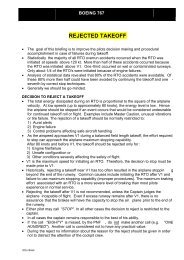
8FIGURE<strong>Angle</strong> <strong>of</strong>attackAPPROACH AOA0.5 degIncreasing altitudeGross weightcan be seen that the optimal long-rangecruise Mach number does not varysignificantly as gross weight (hence,lift and AOA) changes. Superimposedon this chart are two lines <strong>of</strong> constantAOA. It is apparent that flying aconstant AOA will not yield optimalperformance. If a flight crew tried to flya target AOA and there was an error <strong>of</strong>as little as 0.5 deg, the penalty in fuelmileage could be 3 percent or more.Wind is a more fundamental consideration.For best fuel mileage in a headwind,the airplane should be flownfaster than the speed for best range instill air; in a tailwind, it should beflown more slowly. Most modern <strong>Boeing</strong>airplanes have a flight managementcomputer (FMC) that accounts for airplane,engine, and wind characteristicsand can compute the optimal speedto be flown.Approach speed. Approach speed iscritical to landing performance and isestablished during the airplane certificationprocess. It is determined notonly by margin above stall speed butalso may be increased by consideration<strong>of</strong> minimum control speed andtail clearance at touchdown.Regulations require that the approachspeed be no smaller than a specificmultiple <strong>of</strong> the stall speed. Becausestall speed is a function <strong>of</strong> Mach number,stall-limited approach speed willoccur at a different AOA at differentgross weights and altitudes (fig. 8).Those airplanesthat do not accountfor the variation<strong>of</strong> stall speed withMach number setthe approach speedat the most conservativealtitude.The speeds alsoallow for the mostadverse CG (forward)that requires themost lift out <strong>of</strong> thewing, resulting inthe highest stallspeed and, therefore,the highestapproach speed.In addition, the approach speedcannot be smaller than a multiple<strong>of</strong> the minimum control speed in thelanding configuration (V mcl ). Thisspeed is not significantly influencedby movement <strong>of</strong> the CG. So, duringan approach atthe aft CG, if theflight crewreduces speed t<strong>of</strong>ly at the sameAOA as requiredfor the forwardCG, an approachspeed below theCruiseminimum controlspeed may result.A further considerationis theclearance <strong>of</strong> theaft body from theground as theairplane lands.Some airplanes,particularly thosewith stretchedfuselages, haveincreased approachspeeds to reducethe AOA andhence the pitchangle on touchdown.This providesadequateclearance betweenthe body and theground at themost critical CG.However, in revenue service, CG is rarelyat the forward limit. So, if the approacheswere flown on a daily basis by referenceto a fixed-approach AOA based ona margin above stall, at any CG aft <strong>of</strong>the forward limit, the probability <strong>of</strong> tailstrike would be greater than the currentpractice <strong>of</strong> using approach airspeeds.In addition, variations in thrust will affectthe approach AOA-speed relationship.From the discussion above, it can beseen that approach speed may belimited by many different requirementsand that no single AOA can be targetedto ensure proper speed or landingattitude margins.AOA MEASUREMENTThe previous section dealt with therelationship between the aerodynamics<strong>of</strong> the airplane and the true AOA <strong>of</strong> thewing. In practice, the true AOA <strong>of</strong>the wing is not known. It only can beAOA AND ERRORS IN SPEED AND GROSS WEIGHTAirspeedStall0.5 deg10 kt3RELATIONSHIP BETWEEN AIRSPEED AND AOA0.5 deg<strong>Angle</strong> <strong>of</strong> attack1 ktAn error in AOA corresponds to a much higher errorin airspeed or gross weight at high speeds than at lowspeeds. For a mid-sized airplane, such as the 757-200,a 0.5-deg error in AOA results in the following errors:Flight regime Speed error Gross weight errorHigh speed 10 kt 30,000 lb*Take<strong>of</strong>f/landing 2 kt 6,000 lbStall warning
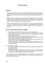
10FIGURESTALL WARNING SCHEDULE<strong>Angle</strong> <strong>of</strong>attackPerformanceimprovementTerminaloperationsmust be in a form other than visualto be effective, even if the flight crewis not looking at the instrument panel.Beginning with early commercial jetliners,standard practice has been toequip these airplanes with a stick shakeras a means <strong>of</strong> stall warning. Someairplanes also have employed sticknudgers or stick pushers to improvestall avoidance and stall characteristics.All these indications have been drivenby an AOA threshold, which is usuallya function <strong>of</strong> flap configuration, landinggear configuration, or both.Because <strong>of</strong> the effect <strong>of</strong> Mach numberon stall AOA, the stall warning AOA typicallywas set at a conservative level toaccommodate gross weight and altitudevariations expected in the terminal area.The early stall warning systemthresholds were not set to be effectiveat cruise altitudes and speeds becausethey did not correct for Mach number(fig. 10). This kept the system simple.The stick shaker was set at an AOAeffective for low altitudes but at toohigh a value for cruise. Natural stallbuffet was found to give satisfactorywarning at higher Mach numbers.Later stall warning systems usedMach number from the pitot or staticair data system to adjust the stallwarning AOA threshold down as Machnumber increased. This provided theflight crew with a stall warning relatedto the actual available performance.However, it also made the stall warningMach-independent scheduleCruiseMach numberMach-dependent scheduleInitial buffetboundarysystem dependent on good pitot andstatic data, a factor that will beconsidered in the next section on thededicated AOA indicator.It should be noted from figure 10that the stall warning schedule doesnot follow the buffet boundary at veryhigh Mach numbers. The buffet here iscaused by Mach buffet, or too high aspeed. Setting the stall warning systemto activate at this point may lead theflight crew to believe the airplane isnear stall and increase, rather thandecrease, speed.11FIGUREAirspeed tapelowerbarber polePitch limit indicator. The PLI originallywas developed as part <strong>of</strong> an industryeffort to address windshear escapetraining. Because stall warning isprimarily a function <strong>of</strong> AOA, the PLIshows AOA margin to stall warning,even though it is part <strong>of</strong> the pitchattitude display (fig. 11). The distancefrom the airplane symbol to the PLI iscalculated from the difference betweenthe AOA <strong>of</strong> the airplane and the AOAat which stall warning will occur. Thisprovides the flight crew with goodsituational awareness, enabling themto monitor airplane attitude in pitchand roll relative to the horizon, whilesimultaneously showing whether theairplane is approaching its maximumAOA. In general, when the airplanesymbol and the amber PLI bars meet,the stall warning system will activate.However, the PLI also is limited to30 deg <strong>of</strong> pitch attitude, regardless <strong>of</strong>AOA. If AOA or AOA margin to stickshaker were to be used as the first andprimary focus <strong>of</strong> the flight crew duringwindshear escape or terrain avoidanceprocedures, extremely high pitchattitudes could be reached before stallwarning if the maneuver is enteredwith sufficient speed. Therefore, thePLI shows the lesser <strong>of</strong> either marginto stick shaker, or 30 deg <strong>of</strong> pitch.PRIMARY FLIGHT DISPLAY STALL WARNING MARGIN INDICATIONSBased onAOA ss – AOA current<strong>Boeing</strong>-designed,series-700modelsPitch limitindicator (PLI)AOA ss – AOA current<strong>AERO</strong>18
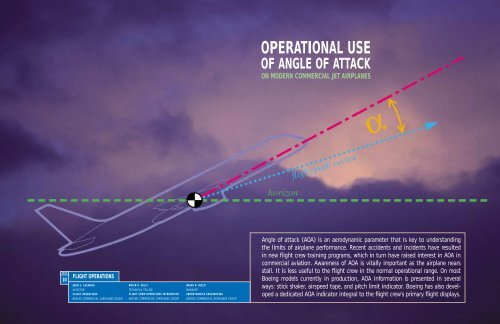
Because stall AOA is a function <strong>of</strong>Mach number, a PLI on airplanes withfixed stall warning schedules woulddisplay an excessively large marginat typical cruise Mach and altitude.To avoid this misleading display, PLIwas available only with flaps extendedwhen it was introduced in the mid-1980s.Later airplanes have employed stallwarning schedules that adjust thestall warning threshold as a function<strong>of</strong> Mach number. The design <strong>of</strong> the777, 717, and 767-400ER has takenadvantage <strong>of</strong> this and will display thePLI full time when flaps are down,as well as when flaps are up if speedor load factor causes stall marginto decrease to an AOA within 1.3 g<strong>of</strong> stall warning.Work is currently under way tointroduce this type <strong>of</strong> PLI indicationon other models. Recent changes tothe 757 and 767 enable the PLI to bedisplayed with flaps up.Speed tape indications. Soon afterthe introduction <strong>of</strong> the PLI, a verticalscale airspeed indicator was developedand added to electronic flight displays.This <strong>of</strong>fered the opportunity tocalculate and place airspeed-relateddata such as maximum, minimum,maneuvering, and reference speeds onthe airspeed instrument (fig. 11). All<strong>Boeing</strong> models currently in productionhave this capability.Of particular interest are the minimumspeed amber and red bands, or barberpole. At low speeds on <strong>Boeing</strong>-designedairplanes currently in production, theseindications are based on sensed AOAand the AOA margin to stick shaker.At higher Mach numbers, most airplaneswith fixed AOA stall warning schedulesshow margins to stick shaker ormargin to initial buffet, whichevercorresponds to the highest speed. Onthese airplanes, the margin to buffetat higher Mach numbers is calculatedby the FMC.On newer models, such as the777 and 767-400, the amber and redbands show margin to stall warningat all times because the stall warningschedule generally follows the initialbuffet boundary at higher speeds up12FIGUREOPTIONAL AOA GAUGE FOR 737-600/-700/-800/-900, 767-400, 777AnalogpointerDigitalreadout6.0to cruise. The position <strong>of</strong> the amberand red bands is always a function <strong>of</strong>AOA margin to stall warning.The speed tape is designed to providethe flight crew with situationalawareness <strong>of</strong> the flight envelope.It shows the crew where the airplanespeed is relative to the limits (i.e.,maximum placard speeds or minimumstall warning speed, as well as themaneuvering capability available).DESIGN AND USES OF A5 SEPARATE AOA INDICATOR<strong>Boeing</strong> and several operators workedtogether to develop the displayformat for an optional AOA indicator(fig. 12). The upper right locationwas chosen as one that can be accomplishedwithout significant rearrangement<strong>of</strong> the existing PFD or electronicflight display formats. The indicatoritself consists <strong>of</strong> an analog scale andpointer, and digital representationsimilar to displays <strong>of</strong> many otherAOA gauge on primary flight displayStall warning (stick shaker) AOAApproach reference bandparameters throughout the flight deck.Stall warning AOA is shown witha red tick mark, which will changeposition as a function <strong>of</strong> Mach numberfor those airplanes with Machdependentstall warning schedules.A green approach reference band isshown whenever landing flaps areselected. The range <strong>of</strong> the approachreference band accounts for normallyexpected variations in CG, thrust,sideslip, and other considerations.Many AOA indicators used in the pasthave been <strong>of</strong> the “normalized” type,where AOA is shown in arbitrary unitsand scaled so that zero load factor isshown as an AOA <strong>of</strong> zero and stallis shown as an AOA <strong>of</strong> one. NormalizedAOA on a commercial jetliner wouldrequire that Mach number be introducedinto the calculation <strong>of</strong> AOAbecause stall AOA and buffet marginsare a function <strong>of</strong> Mach number.The indicator developed shows bodyAOA in degrees and is not normalized,<strong>AERO</strong>19
which is related to the second objectiveabove, that the indicator be usefulwhen pitot or static data, and thereforeMach calculations, are unreliable because<strong>of</strong> blockage or a fault in the system.The pointer <strong>of</strong> a normalized indicator inthis condition would behave erratically,making the indicator unusable.With the nonnormalized design, theposition <strong>of</strong> the needle is a functiononly <strong>of</strong> sensed AOA. The red tick markfor stall warning may behave erraticallyin a pitot or static failure state, as maystick shaker, PLI, and speed tape amberand red bands. However, the AOAneedle and digits will remain stable,and the indicator itself still will beuseful as a backup for unreliableairspeed, provided the AOAvanes are undamaged.A variety <strong>of</strong> potential uses forAOA were examined during thedesign <strong>of</strong> the new AOA indicator:■ Improved situationalawareness and flight crewtraining.■ AOA backup indicationfollowing pitot or staticsystem failures.■ Reference during upsetrecovery, windshearescape, and terrainavoidance maneuvers.■ Indication <strong>of</strong> maximumL/D or range, detection<strong>of</strong> weight errors, and acheck <strong>of</strong> fuel consumptionduring cruise.■ Cross-check to detectweight or configurationerrors on approach toreduce the probability <strong>of</strong>tail strikes on landing.AOA can be used for some <strong>of</strong> thesepurposes, but it does not work aswell for others. From the standpoint<strong>of</strong> flight operations, some <strong>of</strong> the goalscan be met with certain caveats thattake into account the principles andlimitations <strong>of</strong> AOA measurementand aerodynamic performance <strong>of</strong> moderncommercial jet airplanes.■■■■Improved situational awareness andflight crew training. There is a desireto use AOA information to increasethe flight crew’s understanding <strong>of</strong> thephysics <strong>of</strong> flight and their generalawareness <strong>of</strong> the state <strong>of</strong> the wing duringnormal and nonnormal conditions.Within certain limitations, the displayprovides this indication in a clear,unambiguous format. The degree towhich AOA can be used to increaseknowledge and airmanship depends, <strong>of</strong>course, on the approach taken by theairline in training its flight crews andthe use <strong>of</strong> the indicator in training scenariosfor nonnormal procedures. Some<strong>of</strong> the limitations are discussed below.KEY POINTS TO EMPHASIZE IN TRAININGAOA is most useful in high-AOA, low-speedparts <strong>of</strong> the envelope; it is less useful at mostnormal speeds.Airspeed and Mach are still the primary sourcesfor performance data for reasons <strong>of</strong> precision,regulatory basis, system redundancy, and integrity.Therefore, if the AOA indicator is used, flight crewsshould cross-check with other instruments, justas they would with airspeed.The AOA approach reference green band may beused as a cross-check for configuration errors,reference speed calculation errors, or very largeerrors in gross weight. Normal variations in AOAmeasurement dictate the width <strong>of</strong> the green band.Also, because approach speed in some cases canbe determined by issues not related to or sensedby AOA, increasing or decreasing approach speed bytargeting the center <strong>of</strong> the green band can resultin inappropriate approach speeds.Pulling to stick shaker AOA from a high-speed conditionwithout reference to pitch attitude can leadto excessive pitch attitudes and a higher probability<strong>of</strong> stall as a result <strong>of</strong> high deceleration rate.AOA backup indication followingpitot or static system failures. TheAOA instrument described in this articleis useful as a backup for unreliableairspeed indication caused by pitot orstatic source blockage because the calculation<strong>of</strong> indicated AOA is not greatlyaffected by pitot or static pressureinputs for its calibration, and the displayedvalue has not been normalized.Pitot or static system failurerequires the flight crew to take severalfundamental steps to resolve theproblem (see “Erroneous FlightInstrument Information,” Aero no. 8,Oct. 1999):■ Recognize an unusual or suspectindication.■ Keep control <strong>of</strong> the airplanewith basic pitch and power skills.■ Take inventory <strong>of</strong> reliableinformation.■ Find or maintain favorableflying conditions.■ Get assistance from others.■ Use checklists.Recognition <strong>of</strong> a problemwill be accomplished byinstrument scanning andcross-check practices or crewalerts, depending on thedesign <strong>of</strong> the system in theairplane. In this respect, AOAinstruments can be useful asan additional cross-check.Present procedures for unreliableairspeed call for flyingthe airplane by reference topitch attitudes, and referthe pilots to reference tablesshowing pitch attitudes forvarious configurations,weights, and altitudes thatwill result in safe angles <strong>of</strong>attack and speeds. AOA couldbe useful if the relevant datais included in the pitch andpower tables that alreadyexist in the nonnormalchecklist procedures. AOAwould be most useful in flyingthe airplane in multiplefailure conditions where allpitot or static sources areaffected, making all airspeed indicatorsunreliable.Care should be taken when flyingthe airplane by reference to AOA in lieu<strong>of</strong> airspeed. Control should be made byreference to pitch attitude, using AOAas a cross-check to ensure that thepitch attitude results in the desiredspeed or AOA. Attempting to followAOA or speed indications too closely<strong>AERO</strong>20
without stabilizing the airplane in pitchcan lead to an oscillatory flight path.Reference during upset recovery,windshear escape, and terrainavoidance maneuvers. Windshearescape and terrain avoidance maneuversrequire immediate change inpitch attitude and thrust, followedby monitoring <strong>of</strong> the situation andfurther increases in pitch attitude ifneeded, while avoiding stick shakeractivation. The PLI was developedprimarily with these purposes in mindand works well. On all current productionmodels, PLI is shown when flapsare down. At this time, PLI is availablewith flaps retracted on the 717,767-400, 777, and MD-11. Work isunder way to make this capabilityavailable on other <strong>Boeing</strong>-designedmodels currently in production.The first steps in windshear escapeand terrain avoidance proceduresinvolve applying maximum certifiedthrust and control <strong>of</strong> airplane pitchattitude to an initial target, whilehonoring stall warning. AOA margin tostick shaker, whether shown with thePLI or the AOA display, is a secondaryreference during this part <strong>of</strong> themaneuver, not the primary target. Asmentioned in the section on PLI, pitchingup by sole reference to AOA-basedindications can result in excessivelyhigh pitch attitudes if the maneuveris entered at sufficiently high speeds.Because the AOA display is separatefrom the pitch attitude display, it doesnot provide protection against highpitch attitudes if the indicator is usedas the flight crew’s primary focus ortarget during such maneuvers.For upset recovery, either the PLI orthe red stall warning mark on the AOAindicator may be used to assess themargin to stall warning.Indication <strong>of</strong> maximum L/D orrange, detection <strong>of</strong> weight errors,and a check <strong>of</strong> fuel consumptionduring cruise. As shown in the sectionon airplane performance, AOA is not theappropriate parameter for optimizingcruise flight, because <strong>of</strong> the stronginfluence <strong>of</strong> Mach number on airplaneperformance. Because AOA is not verysensitive to speed or weight changesat cruise speeds, even large grossweight errors may not be detectable.A 0.5-deg error in AOA is equivalentto 30,000 lb on a 757-200, or approximately14 percent <strong>of</strong> the maximumtake<strong>of</strong>f weight.Cross-check to detect weight orconfiguration errors on approachto reduce the probability <strong>of</strong> tailstrikes on landing. AOA can be usedduring approach as an extra cross-checkfor errors in configuration, weight, orreference speed calculation. Proximity<strong>of</strong> the barber pole to the referencespeed on the airspeed tape can beused in a similar manner because it isbased on AOA margin to stick shaker.However, for either method, the errorsmust be large enough that they are notmasked by other factors.Normal variations in AOA as a result <strong>of</strong>the regulatory requirements on approachspeed, as well as those caused bydifferences in thrust, CG, sideslip, andthe installed accuracy <strong>of</strong> the AOAmeasurement system, may act togetherto mask all but large errors in weightor configuration. These factors are takeninto account in determining the size<strong>of</strong> the green approach reference band.To keep the size <strong>of</strong> the green bandfrom becoming too large, these variationswere root-sum-squared because<strong>of</strong> the low probability that they wouldall add in the same direction at anyone time. The resulting green band isabout 2 deg wide for the 777 and 3 degfor the 737. The band is centered at anAOA equivalent to V ref +5 kt, assuminga nominal gross weight, mid-CG, nosideslip, a stabilized 3-deg glideslopethrust level, and no system error.A 20,000-lb weight error on a 757,corresponding to approximately10 percent <strong>of</strong> maximum landing grossweight or about a 40 percent error inpayload, yields a change in AOA <strong>of</strong>1.7 deg. So, it can be seen that evenrelatively large weight errors may notbe enough to move the needle out <strong>of</strong>the green band. Conversely, it is alsopossible that flying at the proper speedand configuration may yield an AOAthat is outside the reference band.Figure 13 illustrates how errors can be13AOA GAUGE UNDER VARIOUS CONDITIONS ON APPROACH TO LANDINGFIGURE4.7 6.9 7.5 6.7 6.2Weight error023,000(14%)0016,000(9%)23,000(14%)0CGmidmidmidfwdmidmidaftSpeedV ref + 5V ref + 5V ref + 5V refV ref + 5V ref + 5V ref + 8Speed brakedowndown40%downdowndown40%<strong>AERO</strong>21
masked or canceled out by variationin the other parameters.For these and other reasons, the AOAindicator can be used as an additionalmeans to check for large errors in weightor configuration, but it should not beused as a substitute for current proceduresto establish approach speeds andverify configurations. To determine theapproach speed based solely on placingAOA in the green band can cause situations<strong>of</strong> excessively high or low approachspeeds, depending on a variety <strong>of</strong>circumstances.SUMMARYAOA is a long-standing subject thatis broadly known but one for whichthe details are not broadly understood.While AOA is a very useful andimportant parameter in some instances,it is not useful and is potentiallymisleading in others.■ The relationship between AOAand airplane lift and performanceis complex, depending on manyfactors, such as airplane configuration,Mach number, thrust, and CG.■ AOA information is most importantwhen approaching stall.■ AOA is not accurate enoughto be used to optimize cruiseperformance. Mach number is thecritical parameter.■ AOA information currently isdisplayed on <strong>Boeing</strong> flight decks.The information is used to drivethe PLI and speed tape displays.■ An independent AOA indicator isbeing <strong>of</strong>fered as an option for the737, 767-400, and 777 airplanes.The AOA indicator can be used toassist with unreliable airspeedindications as a result <strong>of</strong> blockedpitot or static ports and mayprovide additional situation andconfiguration awareness to theflight crew.