Installation Instructions for 82T-83T Deadbolt Locks - Best Access ...
Installation Instructions for 82T-83T Deadbolt Locks - Best Access ...
Installation Instructions for 82T-83T Deadbolt Locks - Best Access ...

Create successful ePaper yourself
Turn your PDF publications into a flip-book with our unique Google optimized e-Paper software.
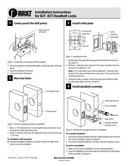
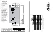
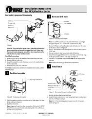
<strong>Installation</strong> <strong>Instructions</strong><strong>for</strong> <strong>82T</strong>–<strong>83T</strong> <strong>Deadbolt</strong> <strong>Locks</strong>1 Center punch the drill points3 Install strike plateHigh side of thedoor bevelCenter punchHeight line5/16”5/16”Clear outJambStrike boxStrike plateFigure 1 Positioning and marking with the template1 Place the template at the desired height, on the high side of the doorbevel.2 Tape the template to the door.3 Center punch the drill points.2 Bore two holesFigure 3 Installing the strike1 Center punch the jamb directly opposite the bolt hole in the door.See Figure 3.2 Drill two 1" diameter holes, located 5/16" above and below the centerpunch to a depth of 1 1/8".Note: For S1 strike plates only, drill two additional 1" diameter holeslocated 15/16" above and below the center punch. Clear out the materialbetween the holes.3 Using the strike as a guide, mortise the jamb and install the strikebox and strike plate as shown in Figure 3.4 Install deadbolt assembly2 1/8” diameter holeSlotted spindle holeDrive-in deadbolt1” diameter holeEdge of doorDrive inFigure 2 Holes <strong>for</strong> standard and drive-in deadbolts1 Bore a 2 1/8" diameter hole. To avoid splintering a wood door, borethe hole from both sides of the door.2 Drill a 1" diameter hole from the edge of the door that intersects the2 1/8" hole.For deadbolts with faceplates■ Using the deadbolt faceplate as a guide, mortise the edge of thedoor to recess the faceplate.Figure 4 Installing the standard and drive-in deadboltsFor standard deadbolts1 Insert the standard deadbolt with the slotted spindle hole at the bottomof the assembly as shown in Figure 4.2 Secure the standard deadbolt to the door with the faceplate screws.For drive-in deadboltsStandard deadboltFaceplate screws1 Make sure the drive-in deadbolt is in the retracted position.2 Insert the deadbolt into the door with the slotted hole at the bottomof the assembly. See Figure 4.T56100/Rev B 1816786 ER-7991-19 May 2000BEST ACCESS SYSTEMSIndianapolis, Indiana
.3 Using a hammer and wooden block, lightlydrive the deadbolt into the hole until theface of the deadbolt is flush with the edgeof the door.5 Install cylinder or cylindersFor 1 3/8” thick doors only■Slip the spacer ring behind the outside cylinderand trim assembly as shownin Figure 5.Note: Use two spacer rings <strong>for</strong> M functiondeadbolts, one behind the outside cylinderand the other behind the inside cylinder.For single-keyed cylinder deadboltsexcept ‘S’ (classroom) functions1 Extend the bolt with a screwdriver.2 Install the cylinder and trim assembly withthe spindle in the vertical position asshown in Figure 5.For non-keyed KL functions1 Extend the bolt with a screwdriver.2 Slip the spacer ring behind the outsiderose.Cylinder & trim assySpacer ring (1 3/8”thick doors)SpindleExtend or retract boltwith screwdriver hereFigure 5 Installing the cylinder and trimassemblyFor ‘S’ (classroom) function deadbolts1 Retract the deadbolt with a screwdriver.2 Install the cylinder and trim assembly withthe spindle in the horizontal position.For double-keyed cylinder deadbolts (‘M’function)1 Extend the bolt with a screwdriver.2 Install each cylinder with its ring and roseas shown in Figure 6.Figure 6 Side view of a double-keyed deadbolt6 Attach inside trimFor standard mounting screws1 Secure the cylinder to the door with theclamp plate and mounting screws asshown in Figure 7.Turn knob assyOutside cylinder,ring, and roseFigure 7 Standard trim mounting2 Break the spindle at the appropriate notchto suit the installation.3 Slide the turn knob assembly over the spindleand secure it with the trim screws supplied.For concealed mounting screws1 With the inside rose and turn knob unit inplace, put the two mounting screwsthrough the outside cylinder as shown inFigure 8.Mounting screwBoth spindles fitthrough slottedspindle holeSpindleClamp plateMounting screwsTrim screwsFigure 8 Concealed trim mountingInside roseTurn knob unitBEST ACCESS SYSTEMSIndianapolis, Indiana2 Break the spindle at the appropriate notchto suit the installation.3 Screw the mounting screws into the backof the turn knob unit.7 Install core or coresFor double-keyed deadbolts or deadboltswith concealed screws■ To cover the mounting screw holes, putthe cylinder face into the ring. See Figure 9.Figure 9 Installing the cylinder face <strong>for</strong> doublekeyeddeadbolts and deadbolts withconcealed screwsFor all deadbolt locks1 Put the control key into the core and turnthe key 15 degrees clockwise as shown inFigure 10.Figure 10 Installing the core on standarddeadbolts2 Adjust the throw pins if needed, then putthe core into the cylinder with the controlkey.3 Turn the key 15 degrees counterclockwiseand remove the key.Caution: <strong>Locks</strong> that secure both sidesof the door are controlled by buildingcodes and the Life Safety Code®. In anemergency exit situation, failure toquickly unlock the door from the insidecould be hazardous or even fatal.PatentsProducts are covered by one or more of thefollowing patents:U.S. PatentsD290085, 4444034, 4424693, 4386510,4294093, 4301667, 4655063, 4843852Other patents pending.RingMounting screw holesCylinder faceThrow pinsCoreRotate 15 degrees


![B.A.S.I.S. G Service Manual [T63300] - Best Access Systems](https://img.yumpu.com/48375082/1/190x245/basis-g-service-manual-t63300-best-access-systems.jpg?quality=85)