MICROWAVE OPTICS - Granular Materials Laboratory
MICROWAVE OPTICS - Granular Materials Laboratory
MICROWAVE OPTICS - Granular Materials Laboratory

Create successful ePaper yourself
Turn your PDF publications into a flip-book with our unique Google optimized e-Paper software.
012-04630F Microwave OpticsTable of ContentsSectionPageCopyright, Warranty, and Equipment Return................................................... iiIntroduction ...................................................................................................... 1Equipment......................................................................................................... 1Initial Setup ...................................................................................................... 3Accessory Equipment ....................................................................................... 3Assembling Equipment for Experiments.......................................................... 5ExperimentsExperiment 1: Introduction to the System ............................................ 7Experiment 2: Reflection ................................................................... 11Experiment 3: Standing Waves - Measuring Wavelengths ............... 13Experiment 4: Refraction Through a Prism....................................... 17Experiment 5: Polarization ................................................................ 19Experiment 6: Double-Slit Interference ............................................ 21Experiment 7: Lloyds Mirror............................................................. 23Experiment 8: Fabry-Perot Interferometer ........................................ 25Experiment 9: Michelson Interferometer .......................................... 27Experiment 10: Fiber Optics.............................................................. 29Experiment 11: Brewster's Angle ...................................................... 31Experiment 12: Bragg Diffraction ..................................................... 33Teacher's Guide .............................................................................................. 35Appendix ........................................................................................................ 45Schematic Diagrams ....................................................................................... 46Replacement Parts List ................................................................................... 47i
Microwave Optics 012-04630FCopyright, Warranty, and Equipment ReturnPlease—Feel free to duplicate this manualsubject to the copyright restrictions below.Copyright NoticeThe PASCO scientific 012-04630E Model WA-9314BMicrowave Optics manual is copyrighted and all rightsreserved. However, permission is granted to non-profiteducational institutions for reproduction of any part of themanual providing the reproductions are used only for theirlaboratories and are not sold for profit. Reproductionunder any other circumstances, without the writtenconsent of PASCO scientific, is prohibited.Limited WarrantyPASCO scientific warrants the product to be free fromdefects in materials and workmanship for a period of oneyear from the date of shipment to the customer. PASCOwill repair or replace at its option any part of the productwhich is deemed to be defective in material or workmanship.The warranty does not cover damage to the productcaused by abuse or improper use. Determination ofwhether a product failure is the result of a manufacturingdefect or improper use by the customer shall be madesolely by PASCO scientific. Responsibility for the returnof equipment for warranty repair belongs to the customer.Equipment must be properly packed to prevent damageand shipped postage or freight prepaid. (Damage causedby improper packing of the equipment for return shipmentwill not be covered by the warranty.) Shipping costs forreturning the equipment after repair will be paid byPASCO scientific.CreditsThis manual edited by: Dave GriffithTeacher’s guide written by: Eric AyarsEquipment ReturnShould the product have to be returned to PASCOscientific for any reason, notify PASCO scientific byletter, phone, or fax BEFORE returning the product. Uponnotification, the return authorization and shippinginstructions will be promptly issued.ÿäÿ NOTE: NO EQUIPMENT WILL BEACCEPTED FOR RETURN WITHOUT ANAUTHORIZATION FROM PASCO.When returning equipment for repair, the units must bepacked properly. Carriers will not accept responsibility fordamage caused by improper packing. To be certain theunit will not be damaged in shipment, observe the followingrules:➀ The packing carton must be strong enough for theitem shipped.➁ Make certain there are at least two inches ofpacking material between any point on theapparatus and the inside walls of the carton.➂ Make certain that the packing material cannot shiftin the box or become compressed, allowing theinstrument come in contact with the packingcarton.Address:PASCO scientific10101 Foothills Blvd.Roseville, CA 95747-7100Phone: (916) 786-3800FAX: (916) 786-3292email: techsupp@pasco.comweb: www.pasco.comii
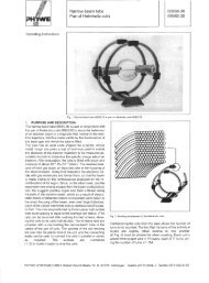
Montage auf MontageplatteFitting on mounting plateMontage sur plaque de montageMontaggio su plastra di montaggioInstalowanie na płycie montażowejZB 4-101-GF1Einbaulage mit Gerätefüßen ZB 4-101-GF1 beliebig Abstand ≥ 50 mm und Derating.Mounting position with fixing clips ZB 4-101-GF1 optional. Distance ≥ 50 mm andDerating must be observed.Position quelconque avec pattes de montage p. ex. ZB 4-101-GF1. Respecter distance≥ 50 mm et la déclassement.Montaggio su piedini ZB 4-101-GF1 (a sceita). Mantenere la distanza ≥ 50 mm e ildeclassamentoOpcjonalna pozycja montażu z uchwytami ZB 4-101-GF1. Należy przestrzegać odległosci ≥ 50 mm oraz skalowania.DeratingI/I e 1,0DéclassementSkalowanie0,90,80,7405055°CD Aufbau waagerecht Aufbau senkrecht/beliebig Umgebungstemperatur06/99 AWA 2727-1773GBInstallation horizontalInstallation vertical/optionalAmbient temperatureF Position horizontale Position verticale /quelconque Température ambianteIMontaggio orizzontaleMontaggio verticale/opzionaleTemperatura ambientePL Montaż poziomy Montaż pionowy/opcjonalnie Temperatura otoczenia8/12
Microwave Optics012-04630FCopy-Ready ExperimentsThe following Experiments provide a thorough introduction to wave theory usingthe microwave system. We expect that the student approaches each experimentwith the appropriate theoretical background, therefore, basic principles are onlybriefly discussed in each experiment.The experiments are written in worksheet format. Feel free to photocopy them foruse in your lab.6
012-04630F Microwave OpticsPurposeProcedureExperiment 1: Introduction to the SystemEQUIPMENT NEEDED:– Transmitter – Goniometer– Receiver – Reflector (1)This experiment gives a systematic introduction to the Microwave Optics System. This mayprove helpful in learning to use the equipment effectively and in understanding the significance ofmeasurements made with this equipment. It is however not a prerequisite to the following experiments.1 Arrange the Transmitter and Receiver on the Goniometeras shown in Figure 1.1 with the Transmitterattached to the fixed arm. Be sure to adjust bothTransmitter and Receiver to the same polarity—thehorns should have the same orientation, as shown.R2 Plug in the Transmitter and turn the INTENSITYselection switch on the Receiver from OFF to 10X.(The LEDs should light up on both units.)3 Adjust the Transmitter and Receiver so the distancebetween the source diode in theTransmitter and the detector diodein the Receiver (the distance labeledR in Figure 1.1) is 40 cm(see Figure 1.2 for location ofpoints of transmission and reception).The diodes are at the locationsmarked "T" and "R" on thebases. Adjust the INTENSITY andVARIABLE SENSITIVITY dialson the Receiver so that the meterreads 1.0 (full scale).4 Set the distance R to each of thevalues shown in Table 1.1. For eachvalue of R, record the meter reading.(Do not adjust the Receiver controlsbetween measurements.) After makingthe measurements, perform thecalculations shown in the table.5 Set R to some value between 70 and90 cm. While watching the meter,slowly decrease the distance betweenthe Transmitter and Receiver. Doesthe meter deflection increase steadilyas the distance decreases?Effective Point of Emission ofTransmitter Signal5 cm 5 cmTransmitterR(cm)4050607080901007Figure 1.1 Equipment SetupFigure 1.2 Equipment SetupMeter Reading (M)Table 1.1Effective Point of Reception ofTransmitter SignalM X R(cm)ReceiverM X R 2(cm 2 )1.0 40 1600
Microwave Optics012-04630F6 Set R to between 50 and 90 cm. Move a Reflector, its plane parallel to the axis of the microwavebeam, toward and away from the beam axis, as shown in Figure 1.3. Observe the meter readings.Can you explain your observations in steps 5 and 6? Don’t worry if you can’t; you willhave a chance to investigate these phenomena moreclosely in Experiments 3 and 8, later in this manual. Fornow just be aware of the following:äÿIMPORTANT: Reflections from nearby objects, includingthe table top, can affect the results of your microwaveexperiments. To reduce the effects of extraneousreflections, keep your experiment table clear of allobjects, especially metal objects, other than those componentsrequired for the current experiment.7 Loosen the hand screw on the back of the Receiver androtate the Receiver as shown in Figure 1.4. This variesthe polarity of maximum detection. (Look into thereceiver horn and notice the alignment of the detectordiode.) Observe the meter readings through a full 360degree rotation of the horn. A small mirror may behelpful to view the meter reading as the receiver isturned. At what polarity does the Receiver detect nosignal?Try rotating the Transmitter horn as well. When finished,reset the Transmitter and Receiver so their polaritiesmatch (e.g., both horns are horizontal or both hornsare vertical).8 Position the Transmitter so the output surface of the hornis centered directly over the center of the Degree Plate ofthe Goniometer arm (see Figure 1.5). With the Receiverdirectly facing the Transmitter and as far back on theGoniometer arm as possible, adjust the Receiver controlsfor a meter reading of 1.0. Then rotate the rotatable armof the Goniometer as shown in the figure. Set the angleof rotation (measured relative to the 180-degree point onthe degree scale) to each ofthe values shown in Table1.2, and record the meterreading at each setting.Table 1.2Angle ofReceiver0°10°20°30°40°50°MeterReadingAngle ofReceiver70°80°90°100°110°120°60° 130°ReflectorFigure 1.3 ReflectionsFigure 1.4 PolarizationHandscrewFigure 1.5 Signal DistributionMeterReadingAngle ofReceiver140°150°160°170°180°MeterReading8
012-04630F Microwave OpticsQuestions1 The electric field of an electromagnetic wave is inversely proportional to the distance fromthe wave source(i.e., E = 1/R). Use your data from step 4 of the experiment to determine if the meter readingof the Receiver is directly proportional to the electric field of the wave.2 The intensity of an electromagnetic wave is inversely proportional to the square of the distancefrom the wave source (i.e., I = 1/R 2 ). Use your data from step 4 of the experiment to determineif the meter reading of the Receiver is directly proportional to the intensity of the wave.3 Considering your results in step 7, to what extent can the Transmitter output be considered aspherical wave? - A plane wave?9
Microwave Optics012-04630FNotes10
012-04630F Microwave OpticsExperiment 2: ReflectionEQUIPMENT NEEDED:– Transmitter – Goniometer– Receiver – Metal Reflector– Rotating Component HolderProcedure1 Arrange the equipment as shown in figure 2.1with the Transmitter attached to the fixed armof the Goniometer. Be sure to adjust the Transmitterand Receiver to the same polarity; thehorns should have the same orientation asshown.2 Plug in the Transmitter and turn the ReceiverINTENSITY selection switch to 30X.3 The angle between the incident wave from theTransmitter and a line normal to the plane ofthe Reflector is called the Angle of Incidence(see Figure 2.2). Adjust the Rotating ComponentHolder so that the Angle of Incidenceequals 45-degrees.Figure 2.1 Equipment SetupReflector4 Without moving the Transmitter or the Reflector,rotate the movable arm of the Goniometeruntil the meter reading is a maximum. Theangle between the axis of the Receiver horn anda line normal to the plane of the Reflector iscalled the Angle of Reflection.5Measure and record the angle of reflection foreach of the angles of incidence shown in Table 2.1.Angle ofIncidenceAngle ofReflectionFigure 2.2 Angles of Incidence and ReflectionTable 2.1➤ NOTE: At various angle settings the Receiver willdetect both the reflected wave and the wave comingdirectly from the Transmitter, thus giving misleadingresults. Determine the angles for which this is trueand mark the data collected at these angles with anasterisk "*".Angle ofIncidence20°30°40°50°60°70°80°90°Angle ofReflection11
Microwave Optics012-04630FQuestions1 What relationship holds between the angle of incidence and the angle of reflection? Does this relationshiphold for all angles of incidence?2 In measuring the angle of reflection, you measured the angle at which a maximum meter readingwas found. Can you explain why some of the wave reflected into different angles? How does thisaffect your answer to question 1?3 Ideally you would perform this experiment with a perfect plane wave, so that all the Transmitterradiation strikes the Reflector at the same angle of incidence. Is the microwave from the Transmittera perfect plane wave (see Experiment 1, step 7)? Would you expect different results if it were aperfect plane wave? Explain.Questions for Additional Experimentation1 How does reflection affect the intensity of the microwave? Is all the energy of the wave striking theReflector reflected? Does the intensity of the reflected signal vary with the angle of incidence?2 Metal is a good reflector of microwaves. Investigate the reflective properties of other materials.How well do they reflect? Does some of the energy pass through the material? Does the materialabsorb some of it? Compare the reflective properties of conductive and non-conductive materials.12
012-04630F Microwave OpticsExperiment 3: Standing Waves - Measuring Wavelengthsäÿ NOTE: This experiment is best performed using the PASCO Microwave Detector Probe(Model ME-9319), as described in Method A below. However, for those without aprobe, Method B may be used, although in this Method l can not be measured directlyfrom the standing wave pattern.IntroductionProcedureEQUIPMENT NEEDED:– Transmitter – Goniometer– Receiver – Reflector (1)– Component Holder (2) – Microwave Detector Probe (ME-9319 )When two electromagnetic waves meet in space, they superpose. Therefore, the total electricfield at any point is the sum of the electric fields created by both waves at that point. If thetwo waves travel at the same frequency but in opposite direction they form a standing wave.Nodes appear where the fields of the two waves cancel and antinodes where the superposedfield oscillates between a maximum and a minimum. The distance between nodes in thestanding wave pattern is just 1/2 the wavelength (l) of the two waves.Method AIn this experiment, you will reflect the wavefrom the Transmitter back upon itself, creatinga standing wave pattern. By measuring thedistance between nodes in the pattern and multiplyingby two, you can determine the wavelengthof the microwave radiation.1 Arrange the equipment as shown in Figure 3.1.2 Plug the Detector Probe into the side connectoron the Receiver. Face the Receiver horn directlyaway from the Transmitter so that noneof the microwave signal enters the horn. Adjustthe Receiver controls as needed to get a strongmeter reading.3 Slide the Probe along the Goniometer arm (no more than a centimeter or two) until the metershows a maximum reading. Then slide the Reflector (again, no more than a centimeter ortwo) to find a maximum meter reading. Continue making slight adjustments to the Probeand Reflector positions until the meter reading is as high as possible.4 Now find a node of the standing wave pattern by adjusting the Probe until the meter readingis a minimum. Record the Probe Position along the metric scale on the Goniometer arm.Initial Probe Position = _____________________.13ReceiverDetector ProbeFigure 3.1 Equipment SetupReflector
Microwave Optics012-04630F5While watching the meter, slide the Probe along the Goniometer arm until the Probehas passed through at least 10 antinodes and returned to a node. Record the newposition of the Probe and the number of antinodes that were traversed.Antinodes Traversed= __________________________.Final Probe Position = _________________________.6 Use your data to calculate l, the wavelength of the microwave radiation.l =_________________________.7 Repeat your measurements and recalculate l.Initial Probe Position =_________________________.Antinodes Traversed =_________________________.Final Probe Position =_________________________.l =_________________________.Questions1 Use the relationship velocity = ln to calculate the frequency of the microwave signal(assuming velocity of propagation in air is 3x10 8 m/sec).(n = the expected frequency of the microwave radiation -10.525 GHz).Method B1 Set up the equipment as shown in Figure 3.2. Adjust the Receiver controls to get afull-scale meter reading with the Transmitter and Receiver as close together as possible.Slowly move the Receiver along the Goniometer arm, away from the Transmitter.How does this motion effect the meter reading?The microwave horns are not perfect collectors of microwave radiation. Instead, theyact as partial reflectors, so that the radiation from the Transmitter reflects back andforth between the Transmitter and Reflector horns, diminishing in amplitude at eachpass. However, if the distance between the Transmitter and Receiver diodes is equalto nl/2, (where n is an integer and l is the wavelength of the radiation) then all themultiply-reflected waves entering the Receiver horn will be in phase with the primarytransmitted wave. When this occurs, the meter reading will be a maximum. (Thedistance between adjacent positions in order to see a maximum is therefore l/2.)2 Slide the Receiver one or two centimetersalong the Goniometer arm to obtaina maximum meter reading.Record the Receiver position along themetric scale of the Goniometer arm.Initial Position of Receiver =_________________________.14Figure 3.2 Equipment Setup
012-04630F Microwave Optics3 While watching the meter, slide the Receiver away from the Transmitter. Do not stopuntil the Receiver passed through at least 10 positions at which you see a minimum meterreading and it returned to a position where the reading is a maximum. Record the newposition of the Receiver and the number of minima that were traversed.Minima Traversed= _________________________.Final Receiver Position = _________________________.4 Use the data you have collected to calculate the wavelength of the microwave radiation.l = _________________________.5Repeat your measurements and recalculate l.Initial Position of Receiver = _________________________.Minima Traversed = _________________________.Final Receiver Position = _________________________.l = _________________________.Questions1 Use the relationship velocity = ln to calculate the frequency of the microwave signal(assuming velocity of propagation in air is 3x10 8 m/sec).(n = the expected frequency of the microwave radiation -10.525 GHz).15
Microwave Optics012-04630FNotes16
012-04630F Microwave OpticsExperiment 4: Refraction Through a PrismEQUIPMENT NEEDED:– Transmitter– Goniometer– Receiver– Rotating Table– Ethafoam Prism mold with styrene pellets– ProtractorIncidentWaven 1n 2Boundary betweenmediaq 1q 2IntroductionAn electromagnetic wave usually travels in astraight line. As it crosses a boundary betweentwo different media, however, the direction ofpropagation of the wave changes. This changein direction is called Refraction, and it is summarizedby a mathematical relationship knownas the Law of Refraction (otherwise known asSnell’s Law):n 1sinq 1= n 2sinq 2;where q 1is the angle between the direction of propagation of the incident wave and thenormal to the boundary between the two media, and q 2is the corresponding angle for therefracted wave (see Figure 4.1). Every material can be described by a number n, calledits Index of Refraction. This number indicates the ratio between the speed ofelectromegnetic waves in vacuum and the speed of electromagnetic waves in the material,also called the medium. In general, the media on either side of a boundary will have differentindeces of refraction. Here they are labeled n 1and n 2. It is the difference betweenindeces of refraction (and the difference between wave velocities this implies) whichcauses “bending”, or refraction of a wave as it crosses the boundary between two distinctmedia.In this experiment, you will use the law of refraction to measure the index of refractionfor styrene pellets.Procedure1 Arrange the equipment as shown in Figure 4.2. Rotate the empty prism mold and seehow it effects the incident wave. Does itreflect, refract, or absorb the wave?2 Fill the prism mold with the styrene pellets.To simplify the calculations, align the face ofthe prism that is nearest to the Transmitterperpendicular to the incident microwavebeam.3 Rotate the movable arm of the Goniometerand locate the angle q at which the refractedsignal is a maximum.17RefractedWaveFigure 4.1 Angles of Incidence and RefractionEthafoam PrismRotating TableFigure 4.2 Equipment Setup
Microwave Optics012-04630F➤ NOTE: q is just the angle that you read directlyfrom the Degree Scale of the Goniometer.RefractedBeamq = _________________________.q 1q4 Using the diagram shown in Figure 4.3, determine q 1and use your value of q to determine q 2. (You willneed to use a protractor to measure the Prism angles.)q 1= _________________________.q 2= _________________________.5 Plug these values into the Law of Refraction todetermine the value of n 1/n 2.n 1/n 2= _________________________.IncidentBeamq 2Normal toBoundary ofRefractionFigure 4.3 Geometry of Prism Refraction6 The index of refraction for air is equal to 1.00. Use this fact to determine n 1, the index ofrefraction for the styrene pellets.Questions1 In the diagram of Figure 4.3, the assumption is made that the wave is unrefracted when itstrikes the first side of the prism (at an angle of incidence of 0°). Is this a valid assumption?2 Using this apparatus, how might you verify that the index of refraction for air is equal to one.3 Would you expect the refraction index of the styrene pellets in the prism mold to be the same asfor a solid styrene prism?18
012-04630F Microwave OpticsExperiment 5: PolarizationEQUIPMENT NEEDED:-Transmitter-Receiver-Goniometer -Component Holder (1)-Polarizer (1).IntroductionThe microwave radiation from the Transmitter is linearlypolarized along the Transmitter diode axis (i.e., as theradiation propagates through space, its electric field remainsaligned with the axis of the diode). If the Transmitterdiode were aligned vertically, the electric field ofthe transmitted wave would be vertically polarized, asshown in Figure 5.1. If the detector diode were at anangle q to the Transmitter diode, as shown in Figure 5.2,it would only detect the component of the incident electricfield that was aligned along its axis. In this experimentyou will investigate the phenomenon of polarizationand discover how a polarizer can be used to alter thepolarization of microwave radiation.Procedure1 Arrange the equipment as shown in Figure 5.3 andadjust the Receiver controls for nearly full-scalemeter deflection.2 Loosen the hand screw on the back of the Receiverand rotate the Receiver in increments of ten degrees.At each rotational position, record the meterreading in Table 5.1.3 What happens to the meter readings if you continueto rotate the Receiver beyond 180-degrees?Table 5.1TransmitterDiodeFigure 5.1 Vertical PolarizationVerticallyPolarizedMicrowaveDetectorDiodeComponentDetectedFigure 5.2 Detecting Polarized RadiationFigure 5.3 Equipment SetupqVerticallyPolarizedMicrowaves(E field)Angle ofReceiverMeterReadingAngle ofReceiverMeterReadingAngle ofReceiverMeterReading0°70°10°80°20°90°30°100°40°110°50°120°60° 130°140°150°160°170°180°19
Microwave Optics012-04630F4 Set up the equipment as shown in Figure 5.4. Resetthe Receivers angle to 0-degrees (the horns shouldbe oriented as shown with the longer side horizontal).5Record the meter reading when the Polarizer is alignedat 0, 22.5, 45, 67.5 and 90-degrees with respect to thehorizontal.6 Remove the Polarizer slits. Rotate the Receiver so theaxis of its horn is at right angles to that of the Transmitter.Record the meter reading. Then replace the Polar-Figure 5.4 Equipment Setupizer slits and record the meter readings with the Polarizer slits horizontal, vertical, and at 45-Angle ofPolarizer0° (Horiz.)22.5°45°67.5°90° (Vert.)Meter ReadingAngle ofSlitsMeter ReadingHorizontalVertical45°degrees.Questions1 If the Receiver meter reading (M) were directly proportional to the electric field component(E) along its axis, the meter would read the relationship M = M ocosq (where q is the anglebetween the detector and Transmitter diodes and Mo is the meter reading when q = 0). (SeeFigure 5.2). Graph your data from step 2 of the experiment. On the same graph, plot therelationship M ocosq. Compare the two graphs.2 The intensity of a linearly polarized electromagnetic wave is directly proportional to the square ofthe electric field (e.g., I = kE 2 ). If the Receiver’s meter reading was directly proportional to theincident microwave’s intensity, the meter would read the relationship M = M ocos 2 q. Plot this relationshipon your graph from question 1. Based on your graphs, discuss the relationship between themeter reading of the Receiver and the polarization and magnitude of the incident microwave.3 Based on your data from step 5, how does the Polarizer affect the incident microwave?4 Can you explain the results of step 6 of the experiment. How can the insertion of an additional polarizerincrease the signal level at the detector? (ÿ HINT: Construct a diagram like that shown inFigure 5.2 showing (1) the wave from the Transmitter; (2) the wave after it passes through the Polarizer;and (3) the component detected at the detector diode.)20
012-04630F Microwave OpticsExperiment 6: Double-Slit InterferenceIntroductionEQUIPMENT NEEDED:- Transmitter, Receiver - Goniometer, Rotating- Component Holder - Metal Reflectors (2)- Slit Extender Arm - Narrow Slit Spacer- Wide Slit SpacerIn Experiment 3, you saw how two waves moving inopposite directions can superpose to create a standingwave pattern. A somewhat similar phenomenonoccurs when an electromagnetic wave passes througha two-slit aperture. The wave diffracts into twodwaves which superpose in the space beyond the apertures.Similar to the standing wave pattern, there areqpoints in space where maxima are formed and otherswhere minima are formed.With a double slit aperture, the intensity of the wavebeyond the aperture will vary depending on the angleFigure 6.1 Double-Slit Interferenceof detection. For two thin slits separated by a distanced, maxima will be found at angles such thatd sinq = nl. (Where q = the angle of detection, l = the wavelength of the incident radiation,and n is any integer) (See Figure 6.1). Refer to a textbook for more information about the natureof the double-slit diffraction pattern.Procedure1 Arrange the equipment as shown in Figure 6.2. Usethe Slit Extender Arm, two Reflectors, and the NarrowSlit Spacer to construct the double slit. (Werecommend a slit width of about 1.5 cm.) Be precisewith the alignment of the slit and make the setup assymmetrical as possible.2 Adjust the Transmitter and Receiver for vertical polarization(0°) and adjust the Receiver controls to givea full-scale reading at the lowest possible amplification.3 Rotate the rotatable Goniometer arm (on which theReceiver rests) slowly about its axis. Observe the meter readings.Figure 6.2 Equipment Setup4 Reset the Goniometer arm so the Receiver directly faces the Transmitter. Adjust the Receivercontrols to obtain a meter reading of 1.0. Now set the angle q to each of the values shown inTable 6.1. At each setting record the meter reading in the table. (In places where the meter readingchanges significantly between angle settings, you may find it useful to investigate the signallevel at intermediate angles.)21
Microwave Optics012-04630F5Keep the slit widths the same, but changethe distance between the slits by using theWide Slit Spacer instead of the NarrowSlit Spacer. Because the Wide Slit Spaceis 50% wider than the Narrow Slit Spacer(90mm vs 60mm) move the Transmitterback 50% so that the microwave radiationat the slits will have the same relativeintensity. Repeat the measurements.(You may want to try other slit spacings aswell.)Angle0°5°10°15°20°25°Table 6.1Meter Reading Angle45°50°55°60°65°70°Meter ReadingQuestions30°75°1 From your data, plot a graph of meterreading versus q. Identify the angles atwhich the maxima and minima of theinterference pattern occur.35°40°80°85°2 Calculate the angles at which you would expect the maxima and minima to occur in a standard twoslitdiffraction pattern—maxima occur wherever d sinq = nl, minima occur whereverd sinq = nl/2. (Check your textbook for the derivation of these equations, and use the wavelengthmeasured in experiment 3.) How does this compare with the locations of your observed maxima andminima? Can you explain any discrepancies? (What assumptions are made in the derivations of theformulas and to what extent are they met in this experiment?)3 Can you explain the relative drop in intensity for higher order maxima? Consider the single-slit diffractionpattern created by each slit. How do these single slit patterns affect the overall interferencepattern?ÿä NOTE:1 Wavelength at 10.525 GHz = 2.85 cm.2 The experimenter’s body position may affect the results.22
012-04630F Microwave OpticsExperiment 7: Lloyd's MirrorEQUIPMENT NEEDED:- Transmitter - Receiver- Goniometer - Fixed Arm Assembly- Component Holder - Reflector (1)- Meter StickIntroductionIn earlier experiments, such as 3 and 6, you observedhow a single electromagnetic wave can be diffractedBinto two waves and, when the two components joinback together, they form an interference pattern.Lloyd’s Mirror is another example of this phenomenon.Just as with the other interference patterns youhhave seen, this interference pattern provides a convenientmethod for measuring the wavelength of theAradiation.Figure 7.1 is a diagram for Lloyd’s mirror. An electromagneticwave from point source A is detected atd 1d 1point C. Some of the electromagnetic wave, ofFigure 7.1 Lloyd's Mirrorcourse, propagates directly between point A and C,but some reaches C after being reflected at point B. A maximum signal will be detected whenthe two waves reach the detector in phase. Assuming that the diagram shows a setup for a maximumsignal, another maximum will be found when the Reflector is moved back so the pathlength of the reflected beam is AB + BC + l.CProcedure1 Arrange the equipment as shown in Figure 7.2. For best results, the Transmitter and Receivershould be as far apart as possible. Be sure the Receiver and Transmitter are equidistant (d 1) fromthe center of the Goniometer degree plate and that the horns are directly facing each other. (SeeFigure 7.3 for location of effective points of transmission and reception). Also be sure that thesurface of the Reflector is parallel to the axis of theTransmitter and Receiver horns.2 While watching the meter on the Receiver, slowly slidethe Reflector away from the Degree Plate. Notice howthe meter reading passes through a series of minimaand maxima.3 Find the Reflector position closest to the degree platewhich produces a minimum meter reading.4 Measure and record h 1, the distance between the centerof the degree plate and the surface of the Reflector.h 1= _________________________.231.0 meter or moreFigure 7.2 Equipment Setup
Microwave Optics012-04630F5Slowly slide the Reflector away from the degree plate until the meter reading passes through a maximumand returns to a new minimum. Measure and record h 2, the new distance between the centerof the degree plate and the surface of the Reflector.h 2= _________________________.6 Measure d 1the distance between the center of the degree scale and the Transmitter diode.d 1= _________________________.7 Use your collected data to calculate l, the wavelength of the microwave radiation.l = _________________________.8 Change the distance between the Transmitter and Receiver and repeat your measurements.h 1= _________________________.h 2= _________________________.d 1= _________________________.l = _________________________.Effective Point of Emission ofTransmitter SignalEffective Point of Reception ofTransmitter SignalReceiver5 cm 5 cmTransmitterReceiverFigure 7.3 Transmission and Reception PointsQuestions1 What is the advantage in having the effective transmission and reception points equidistant from thecenter of the degree plate in this experiment?äÿ NOTE: Don’t stand in front of the apparatus while conducting the experiment. Your body acts asa reflector. Therefore, try to stand to one side behind the plane of the antenna horn.24
012-04630F Microwave OpticsExperiment 8: Fabry-Perot InterferometerIntroductionEQUIPMENT NEEDED:- Transmitter - Receiver- Goniometer - Component Holders (2)- Partial Reflectors (2)When an electromagnetic wave encounters a partial reflector, part of the wave reflects and part ofthe wave transmits through the partial reflector. A Fabry-Perot Interferometer consists of twoparallel partial reflectors positioned between a wave source and a detector (see Figure 8.1).The wave from the source reflects back and forth between the two partial reflectors. However,with each pass, some of the radiation passes through to the detector. If the distance between thepartial reflectors is equal to nl/2, where l is the wavelength of the radiation and n is an integer,then all the waves passing through to the detector at any instant will be in phase. In this case, amaximum signal will be detected by the Receiver. If the distance between the partial reflectors isnot a multiple of l/2, then some degree of destructive interference will occur, and the signal willnot be a maximum.ProcedurePartial Reflectors1 Arrange the equipment as shown in Figure 8.1. Plug inthe Transmitter and adjust the Receiver controls for aneasily readable signal.2 Adjust the distance between the Partial Reflectors andobserve the relative minima and maxima.3 Adjust the distance between the Partial Reflectors toobtain a maximum meter reading. Record, d 1, thedistance between the reflectors.Figure 8.1 Fabry-Perot Interferometerd 1= _________________________.4 While watching the meter, slowly move one Reflector away from the other. Move the Reflectoruntil the meter reading has passed through at least 10 minima and returned to a maximum.Record the number of minima that were traversed. Also record d 2, the new distance between theReflectors.Minima traversed = _________________________.d 2= _________________________.5Use your data to calculate l, the wavelength of the microwave radiation.l = _________________________.6 Repeat your measurements, beginning with a different distance between the Partial Reflectors.d 1= _________________________. Minima traversed = _________________________.d 2= _________________________. l = _________________________.25
Microwave Optics012-04630FQuestions1 What spacing between the two Partial Reflectors should cause a minimum signal to be deliveredto the Receiver?2 In an optical Fabry-Perot interferometer the interference pattern usually appears as a seriesof concentric rings. Do you expect such a pattern to occur here? Why? Check to see ifthere is one.26
012-04630F Microwave OpticsIntroductionEQUIPMENT NEEDED:Experiment 9: Michelson Interferometer- Transmitter, - Receiver- Goniometer, - Fixed Arm Assembly- Component Holders (2) - Rotating Table, Reflectors (2)- Partial Reflector (1)Like the Fabry-Perot interferometer, the Michelsoninterferometer splits a single wave, then brings theconstituent waves back together so that they superpose,forming an interference pattern. Figure 9.1 shows thesetup for the Michelson interferometer. A and B areReflectors and C is a Partial Reflector. MicrowavesBAtravel from the Transmitter to the Receiver over twodifferent paths. In one path, the wave passes directlyCthrough C, reflects back to C from A, and then is reflectedfrom C into the Receiver. In the other path, thewave reflects from C into B, and then back through Cinto the Receiver.If the two waves are in phase when they reach theReceiver, a maximum signal is detected. By movingone of the Reflectors, the path length of one wavechanges, thereby changing its phase at the Receiver soa maxium is no longer detected. Since each waveFigure 9.1 Michelson Interferometerpasses twice between a Reflector and the Partial Reflector,moving a Reflector a distance l/2 will cause acomplete 360-degree change in the phase of one wave at the Receiver. This causes the meterreading to pass through a minimum and return to a maximum.Procedure1 Arrange the equipment as shown in Figure 9.1. Plug in the Transmitter and adjust the Receiverfor an easily readable signal.2 Slide Reflector A along the Goniometer arm and observe the relative maxima and minima of themeter deflections.3 Set Reflector A to a position which produces a maximum meter reading. Record, x 1, the positionof the Reflector on the Goniometer arm.x 1= _________________________.4 While watching the meter, slowly move Reflector A away from the Partial Reflector. Move theReflector until the meter reading has passed through at least 10 minima and returned to a maximum.Record the number of minima that were traversed. Also record x 2, the new position ofReflector A on the Goniometer arm.Minima traversed = _________________________.x 2= _________________________.27
Microwave Optics012-04630F5Use your data to calculate l, the wavelength of the microwave radiation.l = _________________________.6 Repeat your measurements, beginning with a different position for Reflector A.x 1= _________________________.Minima traversed = _________________________.x 2= _________________________.l = _________________________.Questions1 You have used the interferometer to measure the wavelength of the microwave radiation. If youalready knew the wavelength, you could use the interferometer to measure the distance over whichthe Reflector moved. Why would an optical interferometer (an interferometer using visible lightrather than microwaves) provide better resolution when measuring distance than a microwave interferometer?An Idea for Further InvestigationPlace a cardboard box between the Partial Reflector and Reflector A. Move one of the reflectorsuntil the meter deflection is a maximum. Slowly fill the box with styrene pellets while observing themeter deflections. On the basis of these observations, adjust the position of Reflector A to restore theoriginal maximum. Measure the distance over which you adjusted the reflector. Also measure thedistance traversed by the beam through the pellets. From this data, can you determine the styrenepellets’ index of refraction at microwave frequencies? (The wavelength of electromagnetic radiationin a material is given by the relationship l = l 0/n; where l is the wavelength, l 0is the wavelengthin a vacuum, and n is the index of refraction of the material.) Try boxes of various widths. Youmight also try filling them with a different material.28
012-04630F Microwave OpticsExperiment 10: Fiber OpticsIntroductionEQUIPMENT NEEDED:- Transmitter - Receiver- Goniometer - Tubular Plastic Bags- Styrene PelletsLight can propagate through empty space, but it can also propagate well through certain materials,such as glass. In fiber optics, a thin, flexible glass tube functions as a transmission line forlight from a laser, much as a copper wire can function as a transmission line for electrical impulses.In the same way that variation of the electrical impulses can carry information throughthe copper wire (for example as a phone message), variation in the intensity of the laser light cancarry information through the glass tube.Procedure1 Align the Transmitter and Receiver directly across from each other on the Goniometer, and adjustthe Receiver controls for a readable signal.2 Fill a tubular plastic bag with styrene pellets (tie the end or use a rubber band). Place one end ofthe bag in the Transmitter horn. What happens to the meter reading? Now place the other end inthe Receiver horn. How does the intensity of the detected signal compare to the intensity whenthe bag is not used?3 Remove the plastic bag and turn the Rotatable Goniometer arm until no meter deflection appears.Place one end of the bag in the Transmitter horn, the other in the Receiver horn. Note the meterreading.4 Vary the radius of curvature of the plastic bag. How does this effect the signal strength? Doesthe signal vary gradually or suddenly as the radial curvature of the plastic bag changes? Find theradius of curvature at which the signal begins to drop significantly.Questions1 Check your textbook for information on Total Internal Reflection. Based on the radial curvaturewhen the signal begins to show attenuation as it passes through the plastic bag, determine theangle of total internal reflection for the styrene pellets. Can you use this value to determine theindex of refraction of the styrene pellets?2 Would you expect the plastic bag filled with styrene pellets to work the same with radiation atoptical frequencies? Why?29
Microwave Optics012-04630FNotes30
012-04630F Microwave OpticsExperiment 11: Brewster's AngleIntroductionEQUIPMENT NEEDED:- Transmitter - Receiver- Goniometer - Rotating Table- Polyethylene PanelWhen electromagnetic radiation passes from one media into another, some of the radiationusually reflects from the surface of the new medium. In this experiment, you willfind that the magnitude of the reflected signal depends on the polarization of the radiation.In fact, at a certain angle of incidence—known as Brewster’s Angle—there is an angle ofpolarization for which no radiation will be reflected. (Check your textbook for more informationon Brewster’s Angle.)Procedure1 Arrange the equipment as shown in Figure 11.1, settingboth the Transmitter and the Receiver for horizontalpolarization (90°).2 Adjust the Panel so the angle of incidence of the microwavefrom the Transmitter is 20°. Rotate the Goniometerarm until the Receiver is positioned where it candetect the maximum signal reflected from the Panel.Adjust the Receiver controls for a mid-scale reading,and record the meter reading in Table 11.1.PolyethylenePanelAngle ofIncidenceRotatingTableFigure 11.1 Equipment SetupAngle20°25°30°35°40°45°50°55°60°65°70°75°Table 11.1Meter Reading(Horizontal Polarization)Meter Reading(Vertical Polarization)31
Microwave Optics012-04630F3 Without changing the angles between the transmitted beam, the Polyethylene Panel, and the Receiver,rotate both the Transmitter and the Receiver horns so they align for vertical polarization (0°).Record the new meter reading in the table.4 Repeat steps 2 and 3, setting the angle of incidence to each of the values shown in the table below.At each point set the Transmitter and Receiver for horizontal polarization and record the meter reading;then set them for vertical polarization and record that reading as well.5Plot a graph of “Meter Reading” versus “Angle of Incidence”. Plot both the vertical and horizontalpolarizations on the same graph. Label Brewster’s Angle—the angle at which the horizontally polarizedwave does not reflect.Questions1 Explain how Polaroid sun-glasses can be used to reduce the glare caused by the sun setting over alake or the ocean. Should the glasses be designed to block vertically or horizontally polarized light?2 Could you use the microwave apparatus to locate Brewster’s Angle by examining the transmittedwave rather than the reflected wave? How?32
012-04630F Microwave OpticsExperiment 12: Bragg DiffractionIntroductionEQUIPMENT NEEDED:- Transmitter - Receiver- Goniometer - Rotating Table- Cubic LatticeBragg’s Law provides a powerful tool for investigating crystal structure by relating theinterplanar spacings in the crystal to the scattering angles of incident x-rays. In this experiment,Bragg’s Law is demonstrated on a macroscopic scale using a cubic “crystal” consisting of 10-mmmetal spheres embedded in an ethafoam cube.Before performing this experiment, you should understand the theory behind Bragg Diffraction.In particular, you should understand the two criteria that must be met for a wave to be diffractedfrom a crystal into a particular angle. Namely, there is a plane of atoms in the crystal orientedwith respect to the incident wave, such that:1 The angle of incidence equals the angle of reflection, and2 Bragg's equation, 2dsinq = nl, is satisified; where d is the spacing between the diffractingplanes, q is the grazing angle of the incident wave, n is an integer, and l is the wavelength of theradiation.Cubic Lattice (210)(110)(100)Rotating TableFigure 12.1 Equipment SetupFigure 12.2 "Atomic" Planes of theBragg CrystalProcedure1 Arrange the equipment as shown in Figure 12.1.2 Notice the three families of planes indicated in Figure12.2. (The designations (100), (110), and (210) arethe Miller indices for these sets of planes.) Adjust theTransmitter and Receiver so that they directly faceeach other. Align the crystal so that the (100) planesare parallel to the incident microwave beam. Adjustthe Receiver controls to provide a readable signal.Record the meter reading.33Grazing AngleFigure 12.3 Grazing Angle
Microwave Optics012-04630F3 Rotate the crystal (with the rotating table) one degree clockwise and the Rotatable Goniometer armtwo degrees clockwise. Record the grazing angle of the incident beam and the meter reading. (Thegrazing angle is the complement of the angle of incidence. It is measured with respect to the planeunder investigation, NOT the face of the cube; see Figure 12.3.)4 Continue in this manner, rotating the Goniometer arm two degrees for every one degree rotation ofthe crystal. Record the angle and meter reading at each position. (If you need to adjust theINTENSITY setting on the Receiver, be sure to indicate that in your data.)5Graph the relative intensity of the diffracted signal as a function of the grazing angle of the incidentbeam. At what angles do definite peaks for the diffracted intensity occur?Use your data, the known wavelength of the microwave radiation (2.85 cm), and Bragg’s Law todetermine the spacing between the (100) planes of the Bragg Crystal. Measure the spacing betweenthe planes directly, and compare with your experimental determination.6 If you have time, repeat the experiment for the (110) and (210) families of planes.Questions1 What other families of planes might you expect to show diffraction in a cubic crystal? Would youexpect the diffraction to be observable with this apparatus? Why?2 Suppose you did not know beforehand the orientation of the “inter-atomic planes” in the crystal.How would this affect the complexity of the experiment? How would you go about locating theplanes?The Bragg Diffraction Experiment was developed by Dr. Harry Meiners of Rensselaer PolytechnicInstitute.34
012-04630F Microwave OpticsTeacher's GuideExp 1 – Introduction to the SystemNotes – on Procedure4 The meter reading does not vary with distance in anentirely predictable way, since the microwaves formstanding waves between the transmitter and receiver atcertain distances. In addition, the meter is not directlyrelated to either the electric field or the intensity of theincident beam. The meter is useful for measuring relativeintensity at a constant distance, polarization, andso on.8 The transmitter has a roughly gaussian output distribution,with the 1/e points at about ±20°.5 The meter reading oscillates as the distance is decreased.(See experiment 3, method B)6 The presence of a reflector increases the meter reading.7 The receiver detects no signal when the transmitterand receiver are at 90° to each other.There is no significant difference between the outputdistributions in the horizontal and vertical orientationsAnswers – to Questions1/2 The meter reading is not proportional to either theelectric field or the intensity.3 The transmitter output is more plane wave thanspherical wave, but it has characteristics of both.35
Microwave Optics012-04630FExp 2 – ReflectionNotes – on Procedure5Angle of Incidence Angle of Reflection20° 23°30° 31°40° 41°50° 54°60° 63°70° 85°*80° 78°*90° 70°*The last three points are suspect, due to the spread in theoutput pattern of the transmitter. See experiment 1, part 8.Answers – to Questions1 The angle of incidence equals the angle of reflection.This does hold for all angles, although it is not clear inthis experiment due to the spread in the output pattern.2 Some of the wave appeared to reflect into differentangles; particularly when the angle of incidence was70° or 90°. This is actually a diffraction effect, not reflection.3 The transmitter does not produce a perfect plane wave,and this does affect the results.Answers – to Questions for AdditionalExperimentation1 Intensity of the reflection does vary with the angle ofincidence; from this we can deduce that the reflector isnot 100% efficient.2 In general, conductors will reflect the microwavesmuch better than non-conductors.Exp 3– Standing Waves - Measuring WavelengthsNotes – on Procedure➤ NOTE: There are two different methodsdescribed in this lab. The first method, using theMicrowave Detector Probe, is the easier of thetwo; but either will work.Method A# of antinode Distance Wavelength5 7.1 2.8410 14.1 2.8215 20.0 2.6719 27.5 2.89Frequency:Average: 2.811.07E+10Method B# of antinode Distance Wavelength10 13.3 2.6615 20.5 2.73Average: 2.70Frequency:1.11E+10(Fewer points were taken due to the limited resolutionof this method.)Answers – to QuestionsThe value obtained by the first method was 1.5% off,and the second was 5.6% off. If it is possible to takemore data points on the second method, you may getbetter results.36
012-04630F Microwave OpticsExp 4– Refraction Through a PrismNotes – on Procedure1 The empty foam prism absorbs the radiation by a veryslight amount.3 q = 7° (± 1°)4 q 1= 22°q 2= 29°5/6 Our experimental value was: n 1= 1.3 ± 0.05Answers – to Questions1 This assumption is valid. According to Snell’s law, ifthe angle of incidence is zero, the angle of refraction iszero also.3 The index for a solid styrene prism would be higher,due to the greater “optical” density of the solid material.General Notes1 The prism mold may be filled with other materials aswell. We used water for one such test. The water absorbsmost of the microwave energy (this is how a microwaveoven works) but enough gets through that itmay be measured on the most sensitive scale of thereceiver. We found that n = 1.4 ± 0.05.2 The jar that the styrene pellets are shipped in has beenused as a cylindrical lens, with limited success.37
Microwave Optics012-04630FExp 5– PolarizationNotes – on Procedure2Answers – to Questions1/ 2 The meter reading more closely matches the intensity than it does the electric field.äNOTE: There is a consistent “glitch” in thedata at a polarization angle of about 40 and 140degrees which is not entirely explained by thenon-linearity of the receiver. (This glitch is alsopresent when the polarizer slits are used in part 5of this lab.) If you have an explanation of whythis occurs, please let us know.3 The polarizer transmits only the component of thewave parallel to the polarizer.3 Continued rotation of the receiver results in duplicationof the pattern above.54 When the transmitter and polarizer are at 90°, thewave is completely blocked. Placing a polarizer at 45°,however, introduces a component of the wave parallelto the receiver so that some of the wave is then pickedup.6 The meter reading is zero when the polarizer slits areoriented vertically or horizontally. When the slits areat 45°, the meter reads about 30% of its maximumvalue for that distance.38
012-04630F Microwave OpticsExp 6– Double-Slit InterferenceAnswers – to Questions1/2 For the 7.6 cm spacing, the maxima should occur at22° and 48°.For the 10.6 cm spacing, the maxima should be at 15°,33°, and 54°.These theoretical values are closely matched by theexperimental data. The theory assumes that the distancebetween slit plates and receiver are large comparedto the slit spacing and wavelength. This requirementis barely met in the experimental setup used, andcould cause trouble in some situations.3 The single-slit pattern (see experiment 7) acts as anupper limit to the multiple-slit pattern from this experiment.General Notes1 The position of the experimenter has a definite effecton the measurements in this experiment. Experimentto find just how much effect there is with your particularsetup, and then take your data accordingly.2 Single-slit diffraction may also be attempted on thisapparatus, though we don’t recommend it. The distancesare too short, relative to the wavelength; so theanalysis requires the Fresnel/Kirchoff approach insteadof the Fraunhoffer approximation. Even with theFresnel approach, the “fringes” are too small to beseen adequately.Basically, it doesn’t work well at all.39
Microwave Optics012-04630FExp 7– Lloyd’s MirrorNotes – on Procedure3-8Fringe# h (mm) path length (mm) lambda1 85 7202 138 752 32.103 171 779 26.634 200 806 27.155 227 834 28.116 251 861 27.067 275 890 28.838 298 919 29.139 317 944 25.0810 338 973 28.69average: 27.59stdev: 1.37From this, l = 2.79 cm.Answers – to Questions1 It simplifies the calculations.An alternate method is to graph path length versus fringenumber and take the slope of the graph. This slope will bethe wavelength.40
012-04630F Microwave OpticsExp 8– Fabry-Perot InterferometerNotes – on Procedure1-4 For best results, do not move the reflector closestto the transmitter. There are actually two standingwave patterns that may form: one between the transmitterand first reflector, and one between the two reflectors.(There may also be others, such as betweenthe second reflector and the receiver or the second reflectorand the transmitter; but these will be negligible.)Moving the first reflector will change the amplitudeof the wave coming into the region betweenthe reflectors, and thus give erroneous results.5/6 = 2.85 cm‰ NOTE: An alternate method of analysis is tomake a graph of distance versus fringe number andtake the slope of the line to find the wavelength.l = 2.84 cmAnswers – to QuestionsFirst Plate: 75.2n second plate distance Ð1 54.9 20.32 53.6 21.6 1.33 52.2 23.0 1.44 50.9 24.3 1.35 49.4 25.8 1.56 47.9 27.3 1.57 46.5 28.7 1.48 45.0 30.2 1.59 43.6 31.6 1.410 42.1 33.1 1.511 40.8 34.4 1.312 39.4 35.8 1.413 38.0 37.2 1.414 36.6 38.6 1.415 35.1 40.1 1.516 33.8 41.4 1.317 32.3 42.9 1.518 30.9 44.3 1.419 29.4 45.8 1.520 27.9 47.3 1.521 26.5 48.7 1.422 25.0 50.2 1.5average: 1.421 Minima will occur when the spacing is nl/4, where nis an odd integer.2 We would normally expect just such a pattern; in thiscase, however, the reflectors are too small in relationto the wavelength used; so the next “ring” is locatedbeyond the edge of the reflectors and may not be seen.41
Microwave Optics012-04630FExp 9– Michelson InterferometerNotes – on Procedure1-4 Best results are obtained when the mirrors are botha significant distance from the central beamsplitter. Ifeither mirror is too close to the center, the maximasplits into two peaks due to secondary interference effects.n Refl. Pos. _1 75.02 76.4 1.43 77.9 1.54 79.4 1.55 80.8 1.46 82.2 1.47 83.7 1.58 85.1 1.49 86.6 1.510 88.0 1.411 89.4 1.412 90.9 1.513 92.3 1.414 93.8 1.515 95.2 1.416 96.6 1.417 98.1 1.518 99.5 1.419 101.0 1.520 102.4 1.421 104.0 1.6average: 1.45From this we can calculate the wavelength as being2.90 cm.By this method, we calculate the wavelength as2.89 cm.Answers – to Questions1 The limit of resolution for distance measurements witha Michelson interferometer is roughly 1/4 the wavelengthof the light used. Thus with these microwaves,we can measure distance changes of about 7 mm.With a visible-light interferometer and a wavelength of633 nm (HeNe laser light) we can measure distancechanges of only 158 nm.ä NOTE: An alternate method of analysis is toplot the reflector position versus fringe number.The slope of this line will be half the wavelength.42
012-04630F Microwave OpticsExp 10 – Fiber OpticsNotes – on Procedure2 The meter reading with the “optical fiber” bag in placecan more than double the unobstructed meter reading.This is because the bag prevents the normal spreadingof the beam, and directs all the microwave radiationinto the receiver horn.3 The bag can direct the beam through a full 90° turnwithout measurable attenuation, if the curvature isgradual.4 The signal begins to be attenuated with a radius of curvatureof about 5 cm, and drops off rather suddenly fromthere. It is difficult to get consistent results, though.Answers – to Questions1 Theoretically one can use the radius at which the microwavesbegin to “leak” to determine the index ofrefraction of the material. In reality, this is quite difficult.Our values for n using this method range from1.1 to 1.4.2 The styrene pellets are very small, compared to themicrowave wavelength. Compared to visiblewavelengths, the pellets are enormous. Because ofthis size difference, optical radiation is scattered bythe pellets and microwave radiation is transmitted.Additional IdeaThis apparatus may also be used as a demonstrationof how the plane of polarization can be rotatedby multiple reflections. Rotate the transmitteror receiver 90° to each other, so that no signal getsthrough. Now put the bag of pellets between thetwo. If the bag is held straight, there will be a zerometer reading; but if the bag is curved into a spiral,there will be a non-zero reading.Exp 11– Brewster's AngleNotes – on Procedure1-5Answers – to Questions1 Glare off water from a low source is primarily horizontalin polarization, so sunglasses should be designedto block horizontally polarized light.2 Theoretically, one could do this by finding thepoint at which there was no transmission of verticallypolarized light. We have not been able to getgood results in this experiment, however.General Notes1 The index of refraction of the polyethylene is 1.5.(Calculated from the dielectric constant at 10 GHz)2 One must be careful on this experiment to note thatthere are actually two effects which are being measured.In addition to the Brewster’s angle reflection,there is a certain amount of interference between thefront- and rear-surface reflections from the polyethylene.This interference causes extra peaks at 13.8° and67.2°, and a local minimum at 43.6°. The interferenceis notable enough that you may want to demonstratethat, instead of the Brewster’s angle.43
Microwave Optics012-04630FExp 12– Bragg DiffractionNotes – on Procedure1 The polarization angle of the transmitter and receiver(horizontal or vertical) does not matter.5Answers – to Questions1 Other families of planes would be the 111 plane, the101 plane, and so on. These would be difficult to observewith this apparatus due to the small size of our“crystal”.2 Not knowing the orientation of the interatomic planesof the crystal would increase the complexity of theanalysis. We could orient the crystal so that there wasmaximum transmission; this would indicate to us a100 plane. From there, we could try different anglesuntil we had enough data to assemble a likely pictureof the atomic spacing in the crystal.äÿNOTE: 10-15% error is reasonable for thisexperiment.Peaks occur at 18°, 24°, and 45°. These correspond toplane spacings of 4.6cm, 3.4cm, and 4.0 cm (n = 2 forthe 45° peak) The actual spacing is 3.8 cm The firstpeak is apparently a reflection off a different planethan the one we’re measuring.6 110 Plane:The peak at 29° gives a plane spacing of 2.9 cm; theactual spacing is 2.7 cm44
012-04630F Microwave OpticsAppendixäNOTE: Abnormal behavior (weak or erraticmeter readings, etc.) may be caused by weak batteries.Please make sure your batteries are good beforegiving us a call.äCAUTION: The electronics of the Transmitterand Receiver assemblies contain diodes that are noteasily repairable. An attempt to repair diode assembliesmay void your warranty.Replacing the Receiver BatteryReplacing the Receiver BatteryThe Receiver is powered by two 9-volt alkaline batteries.To replace them, simply remove the back panel of the Receiver(the panel with the rotational scale) by removingthe four screws. Install the new batteries, place them intothe holder as shown below, and replace the panel.ä NOTE: We highly recommend that you use onlyalkaline batteries.Adjusting the Receiver1 Meter mechanical zero adjustment:a. Turn the INTENSITY control to OFF.b. The mechanical zero adjustment is located on themeter, centered just below the meter face. With themeter level and in the horizontal position, use asmall (1/8”) flat-blade screwdriver to adjust themeter needle to read as close to 0 as possible.2 Electronic offset null adjustment:a. Make sure the Transmitter is OFF by unpluggingit.b. Turn the INTENSITY control to the 1X position.c. Turn the VARIABLE SENSITIVITY control allthe way clockwise to its maximum setting.d. The offset null adjustment is located through asmall hole just above the receiver antenna. Use asmall (1/8”) flat-blade screwdriver to adjust themeter reading as close as possible to 0.45
Microwave Optics012-04630FSchematic DiagramsSchematic Diagram, Microwave TransmitterSchematic Diagram, Microwave Receiver46
012-04630F Microwave OpticsReplacement Parts ListPasco Part No. Description Oty.Transmitter003-04319 Transmitter Assembly 1113-132 Resistor, 1.3K, 1/4W, 5% 1113-221 Resistor, 220 OHM, 1/4W 5% 1113-471 Resistor, 470 OHM, 1/4W, 5% 1430-085 IC-LM317T Positive V Reg. 1445-005 Module, Microwave Transmitter 1956-04311 Schematic, Microwave Transmitter 0Receiver003-04313 Receiver Assembly 1004-04312 Receiver P.C.B. Assembly 1113-153 Resistor, 15K, 1/4W, 5% 1113-184 Resistor, 180K, 1/4W, 5% 1113-621 Resistor,620 OHM 1/4W 5% 1123-013 Resistor, 562K 1/4w 1% MF 1123-016 Resistor, 51.1K 1/4w 1% MF 1142-028 Trimpot, 50K 1T .5W CERM SA 1216-026 Capacitor, 1000pF 5% 25V 1412-012 Zener Diode, 1N751A 5.1V 5% .4W 2430-086 IC-LF356N FET OP-AMP DIP 1510-019 Switch, Rotary, 2POLE 6POS 1527-001 L.E.D, Red 1555-02811 Printed Circuit Board 1113-152 Resistor, 1.5K, 1/4W, 5% 1113-300 Resistor, 30 OHM, 1/4W, 5% 1123-2001 Resistor, 2K 1/4W 1% MF 1140-01716 Modified Pot - 5K 1140-040 Pot, 5K 1445-006 Module, Microwave Receiver 1525-008 Meter 1710-04313 Wire List, Microwave Receiver 0956-04312 Schematic, Microwave Receiver 0Components003-01748 Assembly, Partial Reflector 2003-02090 Assembly, Receiver/Transmitter Stand 2003-02091 Assembly, Component Holder 2003-02092 Assembly, Rotating Component Holder 1003-02093 Assembly, Fixed Arm 1003-02094 Assembly, Goniometer 1003-02100 Assembly, Rotating Table 1003-02116 Assembly, Styrene Pellets 1003-02817 Assembly, Slit Extender Arm 1540-002 Battery, 9 Volt, Alkaline 2540-007 AC Adapter, 120VAC, 9VDC 1or 540-013 AC Adapter, 220/240VAC, 9VDC 1648-01749 Metal Reflector 2648-02042 Slit Spacer, Narrow 1648-02043 Slit Spacer, Wide 1648-02052 Polarizer Screen 2648-02082 Ethafoam Prism 1735-027 Plastic Bag, 2 1/2” X 24” 447äÿ NOTE: Replacementparts can be purchasedfrom PASCO or at mostelectronic stores.
Microwave Optics012-04630FNotes48
012-04630F Microwave OpticsTechnical SupportFeedbackIf you have any comments about the product ormanual, please let us know. If you have anysuggestions on alternate experiments or find aproblem in the manual, please tell us. PASCOappreciates any customer feedback. Your input helpsus evaluate and improve our product.To Reach PASCOFor technical support, call us at 1-800-772-8700(toll-free within the U.S.) or (916) 786-3800.fax: (916) 786-3292e-mail: techsupp@pasco.comweb: www.pasco.comContacting Technical SupportBefore you call the PASCO Technical Support staff, itwould be helpful to prepare the following information:➤ If your problem is with the PASCO apparatus,note: Title and model number (usually listed on thelabel); Approximate age of apparatus; A detailed description of the problem/sequence ofevents (in case you can’t call PASCO right away,you won’t lose valuable data); If possible, have the apparatus within reach whencalling to facilitate description of individual parts.➤ If your problem relates to the instruction manual,note: Part number and revision (listed by month andyear on the front cover); Have the manual at hand to discuss yourquestions.49