MICROWAVE OPTICS - Granular Materials Laboratory
MICROWAVE OPTICS - Granular Materials Laboratory
MICROWAVE OPTICS - Granular Materials Laboratory

You also want an ePaper? Increase the reach of your titles
YUMPU automatically turns print PDFs into web optimized ePapers that Google loves.
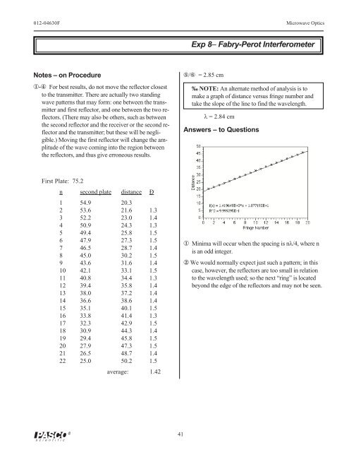
012-04630F Microwave OpticsExp 8– Fabry-Perot InterferometerNotes – on Procedure1-4 For best results, do not move the reflector closestto the transmitter. There are actually two standingwave patterns that may form: one between the transmitterand first reflector, and one between the two reflectors.(There may also be others, such as betweenthe second reflector and the receiver or the second reflectorand the transmitter; but these will be negligible.)Moving the first reflector will change the amplitudeof the wave coming into the region betweenthe reflectors, and thus give erroneous results.5/6 = 2.85 cm‰ NOTE: An alternate method of analysis is tomake a graph of distance versus fringe number andtake the slope of the line to find the wavelength.l = 2.84 cmAnswers – to QuestionsFirst Plate: 75.2n second plate distance Ð1 54.9 20.32 53.6 21.6 1.33 52.2 23.0 1.44 50.9 24.3 1.35 49.4 25.8 1.56 47.9 27.3 1.57 46.5 28.7 1.48 45.0 30.2 1.59 43.6 31.6 1.410 42.1 33.1 1.511 40.8 34.4 1.312 39.4 35.8 1.413 38.0 37.2 1.414 36.6 38.6 1.415 35.1 40.1 1.516 33.8 41.4 1.317 32.3 42.9 1.518 30.9 44.3 1.419 29.4 45.8 1.520 27.9 47.3 1.521 26.5 48.7 1.422 25.0 50.2 1.5average: 1.421 Minima will occur when the spacing is nl/4, where nis an odd integer.2 We would normally expect just such a pattern; in thiscase, however, the reflectors are too small in relationto the wavelength used; so the next “ring” is locatedbeyond the edge of the reflectors and may not be seen.41