
Create successful ePaper yourself
Turn your PDF publications into a flip-book with our unique Google optimized e-Paper software.
ContentsIntroduction 3Features 3Installation Instructions 4Connecting the <strong>SEQ</strong> 5Operation and Calibration 6Input Gain Control 6Mounting Method 7<strong>SEQ</strong> Wiring Diagram-Method 1 9<strong>SEQ</strong> Wiring Diagram-Method 2 10Help - Technical Assistance 11Manufacturing 122
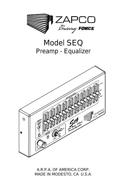
IntroductionCongratulations! You have just chosen the premium in car audioequipment. ZAPCO has well established its place as the technologicalleader in the car audio industry. Because of this, you can rest assuredthat you have the best car audio components in the world.The ZAPCO <strong>SEQ</strong> Stereo preamp/equalizer provides multiple controlfunctions with 9 x 2 bands of graphic equalization (with separate controlsfor each channel) in a compact, heavy-duty die cast package, utilizinglow noise, high slew rate amplifiers throughout.Features• 18 dB boost/cut range on eq bands.• Custom slide pot taper for smooth gain change and better resolution.• Master volume control using high-quality conductive plasticpotentiometers with superior L/R tracking and very low noise.• Input and output LED overload indicators, accurate to within 1 dB ofclipping.• On-off 22 dB cut switch with de-thumping circuitry.• Variable-gain input preamplifier with 6 to 26 dB adjustable gain formatching to low or high output level decks.• Signal to noise >98 dB.• Low impedance output drives long cables.3
Installation InstructionsThe cable supplied with your <strong>SEQ</strong> is comprised of seven wires. Theseseven wires are terminated on one end in a connector designed to beinserted into the back of the <strong>SEQ</strong>. The other wire ends have been leftunterminated.The following are instructions on proper connection of the sevenunterminated wire ends and additional wiring to ensure proper systemgrounding.WIRES INSIDE SHIELDED CABLE:Five wires are contained within the gray jacketed, shielded cable.Signal inputs (to <strong>SEQ</strong>), outputs (from <strong>SEQ</strong>) & signal ground are allcontained within the shielded cable. Function & connection of thesewires are as follows unless otherwise indicated on a tag attached to thecable:Green - Right Channel Input(to <strong>SEQ</strong> from right channel output of source unit)White - Left Channel Input(to <strong>SEQ</strong> from left channel output of source unit)Red - Right Channel Output(from <strong>SEQ</strong> to right channel input of amplifier)Black - Left Channel Output(from <strong>SEQ</strong> to left channel input of amplifier)Bare - Signal Ground(from shielded cable to case of source unit)*WIRES EXTERNAL TO SHIELDED CABLE:Two wires are external to the gray jacketed, shielded cable.Power Input & Power Ground connections are external to the shieldedcable. Function & connection of these wires are as follows:Red - Power Input to <strong>SEQ</strong>(connect to constant, ‘unswitched’, 12V source - fused)**Black - Power Ground(connect to case of source unit)*4
ADDITIONAL GROUND CONNECTIONS:To ensure proper system grounding the following additional connectionsmust be made. RCA Shields & <strong>SEQ</strong> case must be connected to case ofsource unit.RCA Shields -<strong>SEQ</strong> Case -Signal Ground from amplifier inputs (connect wire fromRCA Shields @ amplifier input to case of source unit)*Case Ground from <strong>SEQ</strong>(connect wire from <strong>SEQ</strong> case to case of source unit)** Four separate wires should terminate under the same screw at thecase of the source unit.**Preferably, this connection is made through a 1/4 amp, fast blow, fusedirectly to the car battery.Connecting the <strong>SEQ</strong>The <strong>SEQ</strong> has a special miniature circular 7 pin connector with goldplated pins. The connector snaps into place like other high qualityconnectors. To remove it, squeeze and then pull as shown:Don’t turn - Don’t twist - Don’t use hand tools!1. Squeeze finger grips to flex plastic coupling area. The locking tabswill deflect outward and unlock.2. Pull plug from receptacle.5
Operation and CalibrationA. Input gain controls provide adjustable gain of 6dB to 26dB.B. Input clipping detector flashes whenever input signal is within +/- 1dBof clipping (super-bright LED).C. Volume control: high-quality conductive plastic potentiometer.D. Output clipping detector: indicates the onset of output clipping.E. Equalizer boost/cut controls.F. On/off/mute switch, full output in up position, off in center, mute(-22dB) in down position, (instrumentation type toggle switch.)G. “On”: indicator LED.6
Input Gain ControlCalibration/Adjustment: The pre-amp circuit built into the <strong>SEQ</strong> iscapable of 26dB of gain. Separate left and right channel input gain andadjustments are made via two access holes in the front cover.Adjustment to the input gain may be necessary to match the source(tape deck, tuner or CD) output level to the input sensitivity of the systemamplifiers. If this adjustment is set too low, the source may distortbefore the system is able to achieve full power. If the input gainadjustment is set too high, the internal circuitry of the <strong>SEQ</strong> and/orsystem amplifiers may distort.There are two clipping indicators, one for input stage clipping and one foroutput clipping.Insert a tape or compact disc recorded at high level into the source unit.If the source unit has a balance control, ensure that it is set to center.Set the <strong>SEQ</strong> filter controls flat (0dB). Using the small plastic screwdriverincluded with the <strong>SEQ</strong>, adjust the input gain trim pots fullycounterclockwise. The trimpots are 20-turn pots. Turning each pot morethan 20 full turns counterclockwise will ensure that left & right channelsare matched before the gain adjustment procedure begins. If the sourcehas a volume control, set it from approximately 1/2 to 3/4 full output.With the <strong>SEQ</strong> volume control rotated completely counterclockwise, beginby turning one input gain pot clockwise (count the number of turns) untilthe red input clip indicator flashes. Rotate the other input gain trimpotthe same number of turns as the first. Minor input gain adjustments maybe necessary to achieve left/right balance or for higher level tapes orcompact discs. Setting filter controls at a high boost position may alsocause the preamp output indicator to flash, requiring a reduction in inputgain.7
Mounting MethodBracket MethodAttach bracket to mounting surface placing no. 10 sheet metal ormachine screws through the bracket slots. Attach the bracket to theequalizer using the enclosed 1/4” socket-head screws and nylonshoulder washers. Once the equalizer is swiveled to the desired angle(the <strong>SEQ</strong> may be mounted with the bracket either above or below it)tighten the socket-head screws using a 3/16” allen wrench.Warning: Using screws that are too long will seriously damagecomponents on the circuit board and will void the warranty!Low Profile Mounting MethodLow profile mounting provides 1-5/8” maximum height above themounting surface. The <strong>SEQ</strong> has two holes in the back for low-profilemounting. The connector sticks out of the back therefore, three holesmust be drilled, two for mounting screws (13/64” or 7/32”) and one forthe connector (at least 5/8” in diameter).If the installer has access, one simple way of low profile mounting, is touse 10-32 machine screws (included) threaded into the <strong>SEQ</strong> from therear. (Screws should not be extended into the <strong>SEQ</strong> further than 1”) (seefig. 2). The mounting surface with the 13/64” or 7/32” holes will clear a10-32 screw. Drill 5/8” or larger for the connector.8
Technical AssistanceShould you experience a problem with your <strong>SEQ</strong>, please contact thedealer that sold you this product. If your dealer is unable to solve yourproblem, you may contact the factory service department directly.Phone: (209) 577-4268 Monday-Friday 8am-5pm Pacific timeFax: (209) 577-8548If you need to return this product for repair, please call the factory for areturn authorization number. We will ask you for information which willinclude your name, return shipping address, daytime phone number,model and serial number, and a detailed description of your problem. Aphotocopy of your original purchase receipt is necessary to determinewarranty status and should also be included. Once we issue you a returnauthorization number, please write it in a highly visible area on thepackage. Zapco will not accept any packages that do not have a validreturn authorization number clearly marked on the outside of thepackage.Send all repairs to:A.R.P.A. of America Corp.Attn: Service Department413 S. Riverside Drive, Suite DModesto, CA 9535411
ManufacturingThis product is designed and manufactured in the USA. The followingoperations are ENTIRELY performed in our Modesto, California plant.1. PC Board insertionThe components are inserted into American made printedcircuit boards.2. PC SolderingThe printed circuit board assembly is wave soldered.3. TestingThe PC board is 100% tested to design specs.4. Extrusion MachiningAmerican made aluminum extrusion is cut and machinedto precise tolerances.5. AssemblyThe product is assembled.6. Final TestEvery product is tested with the highest quality audio testequipment to meet or exceed their published specifications.7. Inspection and final packaging.*Many companies claim that their products are built in the USA, but onlya few of the above steps are actually performed in America. Many ofthese companies only do the final assembly, with steps 1 - 4 being doneoutside the USA.12
A.R.P.A. OF AMERICA CORP.413 S. RIVERSIDE DRIVE, SUITE DMODESTO, CA 95354(209) 577-4268FAX (209) 577-8548<strong>SEQ</strong>Rev. E7/96