industrial linear actuators industrial linear actuators
industrial linear actuators industrial linear actuators
industrial linear actuators industrial linear actuators

You also want an ePaper? Increase the reach of your titles
YUMPU automatically turns print PDFs into web optimized ePapers that Google loves.
IntroductionRugged and reliableThomson Tollo <strong>linear</strong> <strong>actuators</strong> incorporate strong, highquality components that has been proven under the hardestoperation conditions to ensure a long and trouble freeoperation.Rugged spur gearings, aircraft quality lubricants, noncorrosive extension tube and high performance motorswith built in thermal protection maximum the life and valuefor the user.Linear actuator advantagesA Thomson Tollo actuator with 100 mm stroke can provide6800 N of force from a 300 mm long package. Thismeans that pneumatic and hyudralic cylinders easily canbe replaced thus saving energy, space and power sourceswhile making control easier and accurate positioningpossible.The <strong>actuators</strong> will operate equally well if pulling or pushingthe load. They hold a load indefi nitely without powerand can be equipped with position feedback devices, limitswitches and other optional functions and features.Broad range of modelsThe broad range of models makes it easy to choose theperfect actuator for your application. We can offer anactuator whether it should be small, fast, quiet, strong,wheater protected or light weight. And if you can not fi ndanything that fi ts among our standard range we are happyto customize an actuator to your needs.Typical applicationsApplications areas where <strong>linear</strong> <strong>actuators</strong> are used includes:• Mobile-off-Highway equipment (harvesters, tractors,trucks, bailers, forestry vehicles, trains, constructionequipment, boats, etc.)• Health and fi tness equipment (x-ray equipment, wheelchairs, handicap adaption of cars, gym equipment,dental chairs, patient lifts, etc.)• In ventilation and valve control• In the operation of windows, gates, doors and hatches• In all type of <strong>industrial</strong> equipment where <strong>linear</strong> motion isa need.3
Electrak LA-seriesElektrak LA1-SElektrak LA1-SP• IP65• 12, 24 or 36 Vdc power supply• Stroke from 25 to 150 mm• End of stroke limit switches• Self locking acme screwElectrak LA10• IP65• 12, 24 or 36 Vdc power supply• Stroke from 50 to 150 mm• Potentiometer feedback (no limit switches)• Self locking acme screw and anti rotation mechanismElectrak LA14• IP65• 12, 24 or 36 Vdc power supply• Standard stroke up to 600 mm• Ball or acme screw• Custom RAL color possible.• IP65• 12, 24 or 36 Vdc power supply• Standard stroke up to 600 mm• Ball or acme screw• Anti rotation mechanism• Aluminium cover tube with T-slot.Electrak LA5Electrak LA24• IP45• 1 × 230 Vac or 3 × 400 Vac power supply• Standard stroke up to 600 mm• Ball or acme screw• Custom RAL color possible.• IP45• 1 × 230 Vac or 3 × 400 Vac power supply• Standard stroke up to 600 mm• Ball or acme screw• Anti rotation mechanism• Aluminium cover tube with T-slot• Version without motor available (ElectrakFA14).7
Electrak LA1 -S and LA1-SPTechnical dataFeatures for both LA1-S and LA1-SP• Small• Weather resistant (IP65)• Withstand 96 hour salt spray test• Motor with auto reset thermal overload protection• Self locking acme screw• Can operate in a large temperature range• Accepts large input voltage variations• Maintenance free• Models with higher load capacity possible on demandFeatures for LA1-SAvailable input voltages [Vdc] 12, 24 or 36Available screw typesAcmeMax. static load at fully retracted [N] 1300Min. / max. standard stroke [inch]S-modelSP-model1 / 62 / 6Duty cycle @ 25° C [%] 25Temperature limits at operation [°C] - 25 to + 65Protection degreeIP65Max. end play [mm] 0,9• End of stroke limit switches• Six standard strokesFeatures for LA1-SP• Potentiometer feedback• Anti rotation mechanism• Three standard strokesOptions• Custom RAL colorRestraining torque [Nm]S-modelSP-model2,3–Engineering notes• No clutchWire cross section [mm 2 ] 1Wire length [mm] 100Connector includedyesPerformance tableStandard strokesModelMax.dynamicload [N]Speed@ min. load[mm/s]Speed@ max. load[mm/s]LA1-SorderingstrokeActual strokeS[mm]LA1-SPorderingstrokeActual strokeS[mm]S(P)12–09A04 110 75 52S(P)24–09A04 110 75 52S(P)12–09A08 225 45 33S(P)24–09A08 225 45 33S(P)12–17A08 340 26 17S(P)24–17A08 340 26 17S(P)12–17A16 340 14 7S(P)24–17A16 340 14 701 2102 4603 7204 9705 12206 14802 5904 11506* 171* not possible with gear ratio 16:18
Electrak LA10Technical dataFeaturesAvailable input voltages [Vdc] 12, 24 or 36Available screw typesAcme or BallMax. static load at fully retracted [N]Acme screw modelsBall screw models11 35018 000Min. / max. standard stroke [inch] 4 / 24Duty cycle @ 25° C [%] 25Temperature limits at operation [°C] - 25 to + 65Protection degreeIP65Max. end play [mm] 1Restraining torque [Nm] 11,3• Rugged and robust• Weather resistant (IP65)• Withstand 96 hour salt spray test• Overload clutch (set to 1,2 – 1,5 × max. permissible load)• Motor with auto reset thermal overload protection• Acme or ball screw drive• Holding brake prevents back driving on ball screw models• Acme screw models are self-locking• Safety nut on all ball screw models• Can operate in a large temperature range• Accepts large input voltage variations• Maintenance freeOptions• Potentiometer feedback• Hand wind• Custom RAL colorWire cross section [mm 2 ] 2Wire length [mm] 165Connector includedyesPerformance tableStandard strokesModelMax.dynamicload [N]Speed@ min. load[mm/s]Speed@ max. load[mm/s]Orderingstroke[inch]Actual strokeS[mm]D12–05A5 1100 54 32D24–05A5 1100 54 32D12–05B5 2250 61 37D24–05B5 2250 61 37D12–10A5 2250 30 18D24–10A5 2250 30 18D12–10B5 4500 30 19D24–10B5 4500 30 19D12–20A5 2250 15 12D24–20A5 2250 15 124 1026 1528 20310 25412 30514 35616 40618 45720 50824 610D12–20B5 4500 15 12D24–20B5 4500 15 12D12–21B5 6800 15 11D24–21B5 6800 15 1110
Electrak LA10DimensionsAcme screw driven modelsBall screw driven modelsPerformance diagrams11
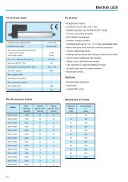
Electrak LA14Technical dataFeaturesAvailable input voltages [Vdc] 12, 24 or 36Available screw typesAcme or BallMax. static load at fully retracted [N]Acme screw modelsBall screw models11 35018 000Min. / max. standard stroke [mm] 50 / 600Duty cycle @ 25° C [%] 25Temperature limits at operation [°C] - 25 to + 65Protection degreeIP65Max. end play [mm] 1Restraining torque [Nm] –Wire cross section [mm 2 ] 2Wire length [mm] 165Connector includedyes• Rugged and robust• Aluminium cover tube with T-slot• Position sensors can be fi tted to the T-slots• Trunnion mounting possible• Anti rotation mechanism• Weather resistant (IP65)• Overload clutch (set to 1,2 – 1,5 × max. permissible load)• Motor with auto reset thermal overload protection• Acme or ball screw drive• Holding brake prevents back driving on ball screw models• Acme screw models are self-locking• Safety nut on all ball screw models• Can operate in a large temperature range• Accepts large input voltage variations• Maintenance freeOptions• Potentiometer feedback• Hand wind• Custom RAL colorPerformance tableStandard strokesModelMax.dynamicload [N]Speed@ min. load[mm/s]Speed@ max. load[mm/s]Orderingstroke[cm]Actual strokeS[mm]DA12–05A65 1100 54 32DA24–05A65 1100 54 32DA12–05B65 2250 61 37DA24–05B65 2250 61 37DA12–10A65 2250 30 18DA24–10A65 2250 30 18DA12–10B65 4500 30 19DA24–10B65 4500 30 19DA12–20A65 2250 15 12DA24–20A65 2250 15 12DA12–20B65 4500 15 12DA24–20B65 4500 15 125 5010 10015 15020 20025 25030 30035 35040 40045 45050 50055 55060 600DA12–21B65 6800 15 11DA24–21B65 6800 15 1112
Electrak LA14DimensionsAcme screw driven modelsBall screw driven modelsPerformance diagrams13
Electrak LA5Technical dataFeaturesAvailable input voltages [Vac] 1 × 230 or 3 × 400Input frequency [Hz] 50Available screw typesAcme or BallMax. static load at fully retracted [N]Acme screw modelsBall screw models11 35018 000Min. / max. standard stroke [inch] 4 / 24Duty cycle @ 25° C [%] 25Max. operation time [s] 45Temperature limits at operation [°C] - 25 to + 65Protection degreeIP45Max. end play [mm] 1Restraining torque [Nm] 12Wire cross section [mm 2 ] 1,5Wire length [mm] 600• Rugged and robust• Overload clutch (set to 1,2 – 1,5 × max. permissible load)• Motor with auto reset thermal overload protection• Acme or ball screw drive• Holding brake prevents back driving on ball screw models• Acme screw models are self-locking• Anti coast brake on all ball screw models (optional onacme models)• Safety nut on all ball screw models• Can operate in a large temperature range• Accepts large input voltage variations• Maintenance freeOptions• Potentiometer feedback• Hand wind• Custom RAL colorEngineering notes• Capacitor (10 µF) necessary on 230 Vac models,p/no. D9200-448-003Connector includednoPerformance tableStandard strokesModelMax.dynamicload [N]Speed@ min. load[mm/s]Speed@ max. load[mm/s]Bestellter Orderingstroke Hub[Zoll]] [inch]Tatsächlicher Actual stroke HubS[mm]A22–05A5 1100 48 38A22–05B5 2250 61 37A42–05B5 2250 61 37A22–10A5 2250 30 18A42–10A5 2250 30 18A22–10B5 4500 30 19A42–10B5 4500 30 19A22–20A5 2250 15 12A42–20A5 2250 15 12A22–20B5 4500 15 124 101,6 1026 152,48 203,210 254,012 304,8 30514 355,6 35616 406,418 457,220 508,024 609,6 610A42–20B5 4500 15 12A22–21B5 6800 15 11A42–21B5 6800 15 1114
Electrak LA5DimensionsAcme screw driven modelsBall screw driven modelsPerformance diagrams15
Electrak LA24Technical dataAvailable input voltages [Vac] 1 × 230 or 3 × 400Input frequency [Hz] 50Available screw typesAcme or BallMax. static load at fully retracted [N]Acme screw modelsBall screw models11 35018 000Min. / max. standard stroke [mm] 50 / 600Duty cycle @ 25° C [%] 25Max. operation time [s] 45Temperature limits at operation [°C] - 25 to + 65Protection degreeIP45Max. end play [mm] 1Restraining torque [Nm] –Wire cross section [mm 2 ] 1,5Wire length [mm] 600Connector includednoFeatures• Rugged and robust• Aluminium cover tube with T-slot• Position sensors can be fi tted to the T-slots• Trunnion mounting possible• Anti rotation mechanism• Withstand 96 hour salt spray test• Overload clutch (set to 1,2 – 1,5 × max. permissible load)• Motor with auto reset thermal overload protection• Acme or ball screw drive• Holding brake prevents back driving on ball screw models• Acme screw models are self-locking• Safety nut on all ball screw models• Can operate in a large temperature range• Accepts large input voltage variations• Maintenance freeOptions• Potentiometer feedback• Hand wind• Custom RAL colorEngineering notes• Capacitor (10 µF) necessary on 230 Vac modelsPerformance tableStandard strokesModelMax.dynamicload [N]Speed@ min. load[mm/s]Speed@ max. load[mm/s]Orderingstroke[cm]Actual strokeS[mm]AA22–05A65 1100 48 38AA22–05B65 2250 52 45AA42–05B65 2250 52 45AA22–10A65 2250 28 24AA42–10A65 2250 28 24AA22–10B65 4500 28 24AA42–10B65 4500 28 24AA22–20A65 2250 14 11AA42–20A65 2250 14 11AA22–20B65 4500 14 11AA42–20B65 4500 14 11AA22–21B65 6800 12 115 5010 10015 15020 20025 25030 30035 35040 40045 45050 50055 55060 600AA42–21B65 6800 12 1116
Electrak LA24DimensionsAcme screw driven modelsBall screw driven modelsPerformance diagrams17
Electrak FA14 (no motor)Technical dataAvailable screw typesAcme or BallMax. static load at fully retracted [N]Acme screw modelsBall screw models11 35018 000Min. / max. standard stroke [mm] 100 / 600Max. input speed [rpm] 3000Max. input torque [Nm] 1,8Max. end play [mm] 1Restraining torque [Nm] –Features• Rugged and robust• Motor fi tted by customer• Aluminium cover tube with T-slot• Position sensors can be fi tted to the T-slots• Trunnion mounting possible• Anti rotation mechanism• Overload clutch (set to 1,2 – 1,5 × max. permissible load)• Acme or ball screw drive• Holding brake prevents back driving on ball screw models• Acme screw models are self-locking• Safety nut on all ball screw models• Maintenance freeOptions• Hand wind• Custom RAL colorPerformance tableStandard strokesModelMax.dynamicload [N]Speed@ max. load[mm/s]*Orderingstroke[cm]Actual strokeS[mm]FA14–05A65 1100 32FA14–05B65 2250 37FA14–10A65 2250 18FA14– 0B65 4500 19FA14–20A65 2250 12FA14–20B65 4500 12FA14–21B65 6800 11*Recommended value5 5010 10015 15020 20025 25030 30035 35040 40045 45050 50055 55060 60018
Electrak FA14 (no motor)DimensionsAcme screw driven modelsBall screw driven models19
Ordering keysElectrak LA1-SDesignation example S 12 – 09A04 – 02Actuator typeLA1-S (with end of stroke limit switches)SSupply voltage12 Vdc24 Vdc36 Vdc122436Hyphen –Gear ratio / screw type / screw lead9:1 / acme screw / 6,35 mm9:1 / acme screw / 3,18 mm17:1 / acme screw / 3,18 mm17:1 / acme screw / 1,59 mm09A0409A0817A0817A16Hyphen –Stroke21 mm46 mm72 mm97 mm122 mm148 mm010203040506Electrak LA1-SPDesignation example SP 12 – 09A04 – 02Actuator typeLA1-SP (with feedback potentiometer)SPSupply voltage12 Vdc24 Vdc36 Vdc122436Hyphen –Gear ratio / screw type / screw lead9:1 / acme screw / 6,35 mm9:1 / acme screw / 3,18 mm17:1 / acme screw / 3,18 mm17:1 / acme screw / 1,59 mm (not possible with 171,5 mm stroke)09A0409A0817A0817A16Hyphen –Stroke59 mm115 mm172 mm (not possible with gear and screw combination 17A16)02040620
Ordering keysElectrak LA10Designation example D 24 – 10B5 – 06 M0 NActuator typeLA10DSupply voltage12 Vdc24 Vdc36 Vdc122436Hyphen –Gear ratio / screw type / screw lead5:1 / acme screw / 5,08 mm10:1 / acme screw / 5,08 mm20:1 / acme screw / 5,08 mm5:1 / ball screw / 5,08 mm10:1 / ball screw / 5,08 mm20:1 / ball screw / 5,08 mm20:1 / ball screw / 5,08 mm with hardened gear05A510A520A505B510B520B521B5Engineering unitInch –Stroke4 inch (102 mm)6 inch (152 mm)8 inch (203 mm)10 inch (254 mm)12 inch (305 mm)14 inch (356 mm)16 inch (406 mm)18 inch (457 mm)20 inch (508 mm)24 inch (610 mm)04060810121416182024Adaptor hole position (for definition see page 26)Rear adaptor 0° (standard position)Rear adaptor 30°Rear adaptor 60°Rear adaptor 90°Rear adaptor 120°Rear adaptor 150°M0M1M2M3M4M5Anti coast brakeNo anti coast brakeNOptionsNo option - leave position blankFeedback potentiometerHand windPOHW21
Ordering keysElectrak LA14Designation example DA 24 – 20A65 M 25 MF N POActuator typeLA14DASupply voltage12 Vdc24 Vdc36 Vdc122436Hyphen –Gear ratio / screw type / screw diameter / screw lead5:1 / acme screw / 15,88 mm / 5,08 mm10:1 / acme screw / 15,88 mm / 5,08 mm20:1 / acme screw / 15,88 mm / 5,08 mm5:1 / ball screw / 15,88 mm / 5,08 mm10:1 / ball screw / 15,88 mm / 5,08 mm20:1 / ball screw / 15,88 mm / 5,08 mm20:1 / ball screw / 15,88 mm / 5,08 mm with hardened gear05A6510A6520A6505B6510B6520B6521B65Engineering unitMetricMStroke5 cm10 cm15 cm20 cm25 cm30 cm35 cm40 cm45 cm50 cm55 cm60 cm051015202530354045505560Adaptor hole position (for definition see page 26)Rear adaptor 0° (standard position)Rear adaptor 30°Rear adaptor 60°Rear adaptor 90°Rear adaptor 120°Rear adaptor 150°Rear and front adaptor 90°M0M1M2M3M4M5MFAnti coast brakeNo anti coast brakeNOptionsNo option - leave position blankFeedback potentiometerHand windPOHW22
Ordering keysElectrak LA5Designation example A 22 – 10B5 – 04 M0 B HWActuator typeLA5ASupply voltage1 × 230 Vac, 50 Hz3 × 400 Vac, 50 Hz2242Hyphen –Gear ratio / screw type / screw diameter / screw lead5:1 / acme screw / 15,88 mm / 5,08 mm (not possible with 400 Vac motor)10:1 / acme screw / 15,88 mm / 5,08 mm20:1 / acme screw / 15,88 mm / 5,08 mm5:1 / ball screw / 15,88 mm / 5,08 mm10:1 / ball screw / 15,88 mm / 5,08 mm20:1 / ball screw / 15,88 mm / 5,08 mm20:1 / ball screw / 15,88 mm / 5,08 mm with hardened gear05A510A520A505B510B520B521B5Engineering unitInch –Stroke4 inch (102 mm)6 inch (152 mm)8 inch (203 mm)10 inch (254 mm)12 inch (305 mm)14 inch (356 mm)16 inch (406 mm)18 inch (457 mm)20 inch (508 mm)24 inch (610 mm)04060810121416182024Adaptor hole position (for definition see page 26)Rear adaptor 0° (standard position)Rear adaptor 30°Rear adaptor 60°Rear adaptor 90°Rear adaptor 120°Rear adaptor 150°M0M1M2M3M4M5Anti coast brakeNo anti coast brakeAnti coast brakeNBOptionsNo option - leave position blankFeedback potentiometerHand windPOHW23
Ordering keysElectrak LA24Designation example AA 42 – 20A65 M 30 M3 N HWActuator typeLA24AASupply voltage1 × 230 Vac, 50 Hz3 × 400 Vac, 50 Hz2242Hyphen –Gear ratio / screw type / screw diameter / screw lead5:1 / acme screw / 15,88 mm / 5,08 mm (not possible with 400 Vac motor)10:1 / acme screw / 15,88 mm / 5,08 mm20:1 / acme screw / 15,88 mm / 5,08 mm5:1 / ball screw / 15,88 mm / 5,08 mm10:1 / ball screw / 15,88 mm / 5,08 mm20:1 / ball screw / 15,88 mm / 5,08 mm20:1 / ball screw / 15,88 mm / 5,08 mm with hardened gear05A6510A6520A6505B6510B6520B6521B65Engineering unitMetricMStroke5 cm10 cm15 cm20 cm25 cm30 cm35 cm40 cm45 cm50 cm55 cm60 cm051015202530354045505560Adaptor hole position (for definition see page 26)Rear adaptor 0° (standard position)Rear adaptor 30°Rear adaptor 60°Rear adaptor 90°Rear adaptor 120°Rear adaptor 150°Rear and front adaptor 90°M0M1M2M3M4M5MFAnti coast brakeNo anti coast brakeAnti coast brakeNBOptionsNo option - leave position blankFeedback potentiometerHand windPOHW24
Ordering keysElectrak FA14Designation example FA14 – 10A65 M 40 M0 NActuator typeFA14 (actuator without motor)FA14Hyphen –Gear ratio / screw type / screw diameter / screw lead5:1 / acme screw / 15,88 mm / 5,08 mm10:1 / acme screw / 15,88 mm / 5,08 mm20:1 / acme screw / 15,88 mm / 5,08 mm5:1 / ball screw / 15,88 mm / 5,08 mm10:1 / ball screw / 15,88 mm / 5,08 mm20:1 / ball screw / 15,88 mm / 5,08 mm20:1 / ball screw / 15,88 mm / 5,08 mm with hardened gear05A6510A6520A6505B6510B6520B6521B65Engineering unitMillimeterMStroke5 cm10 cm15 cm20 cm25 cm30 cm35 cm40 cm45 cm50 cm55 cm60 cm051015202530354045505560Adaptor hole position (for definition see page 26)Rear adaptor 0° (standard position)Rear adaptor 30°Rear adaptor 60°Rear adaptor 90°Rear adaptor 120°Rear adaptor 150°Rear and front adaptor 90°M0M1M2M3M4M5MFAnti coast brakeNo anti coast brakeNOptionsNo option - leave position blankHand windHW25
Options and accessoriesRear adaptor hole positionLA5LA10LA14LA24FA14Hand windLA5LA10LA14LA24FA14Gear ratio X Y5:1 49,6 38,010:1 43,3 43,220:1 38,9 38,0Rear and front adaptor hole in 90°LA14LA24FA14SensorsLA14LA24FA14CapacitorLA5LA24Sensor dataMax. power [W] 10Max. voltage [Vdc] 43,3Max. current [A] 0,5Max. contact resistance [ohm] 0,2Cable: 2 × 0,75 mm 2 , length 170 mmLead data [mm 2 ] 0,12A 10 µF capacitor is necessary for all 1 × 230 Vac <strong>actuators</strong>.Normally open D535 070Capacitor 10 µFD9200-448-003Normally closed D535 07126
Options and accessoriesMounting pinsLA5LA10Trunnion pinsLA14LA24FA14LA14LA24FA14LA14, LA24, FA14 (2 ×) D603 022Trunnion pin bracketsLA5, LA10 (2 ×) D603 028LA14LA24FA14LA14, LA24, FA14 (2 ×) D603 023Mounting pin bracketsLA14LA24FA14LA14, LA24, FA14 (2 ×) D603 030LA14, LA24, FA14 (2 ×) D603 02927
– Page intentionally left blank –28
Electrak PPA-seriesElektrak PPA-DC• Robust and vesatile• Trunnion to clevis mounting• 12, 24 or 36 Vdc• Ball screw driven• Stroke from 102 to 914 mm• Speed from 12 to 33 mm/s• Load up to 6670 N• Maintenance free• End of stroke limit switches available as option• Feedback potentiometer available as option• Hall effect position sensor available as optionElektrak PPA-AC• Robust and vesatile• Trunnion to clevis mounting• 110 or 230 Vac power supply• Ball screw driven• Stroke from 102 to 914 mm• Speed from 5 to 15 mm/s• Load up to 6670 N• Motor with auto reset thermal overload protection• Maintenance free• End of stroke limit switches available as option• Feedback potentiometer available as option• Hall effect position sensor available as option29
Electrak PPA-DCTechnical dataFeaturesAvailable input voltages [Vdc] 12, 24 or 36Available screw typesBallMax. static load at fully retracted [N] 13 350Min. / max. standard stroke [inch] 4 / 36Duty cycle @ 20° C [%] 30Temperature limits at operation [°C] - 25 to + 65Max. end play [mm] 1Wire cross section [mm 2 ] 2• Robust and versatile• Overload clutch• Ball screw drive• Holding brake prevents back driving• Can operate in a large temperature range• Accepts large input voltage variations• Maintenance free• Trunnion to clevis mountingOptions• Potentiometer feedback• Hall effect feedback• End of stroke limit switches• Protective bellowsWire length [mm] 400Connector includednoPerformance tableStandard strokesModelMax.dynamic load[N]Speed@ min. load[mm/s]Speed@ max. load[mm/s]Orderingstroke[inch]Actual strokeS[mm]PPA12–18B65 3330 33 28PPA24–18B65 3330 33 28PPA36–18B65 3330 33 28PPA12–58B65 6670 12 10PPA24–58B65 6670 12 10PPA36–58B65 6670 12 104 1028 20312 30518 45724 61036 91430
Electrak PPA-DCDimensions12, 24 and 36 Vdc modelsPerformance diagrams31
Electrak PPA-ACTechnical dataFeaturesAvailable input voltages [Vac] 1 × 110 or 1 × 230Input frequency [Hz] 50 / 60Available screw typesBallMax. static load at fully retracted [N] 13 350Min. / max. standard stroke [inch] 4 / 36Max. coast distance (without anti coast orelectrical brake option) [mm] 1,6Duty cycle @ 20° C [%] 30Temperature limits at operation [°C] - 25 to + 65Max. end play [mm] 1Wire cross section [mm 2 ] 0,75Wire length [mm] 500• Robust and versatile• Overload clutch• Motor with auto reset thermal overload protection• Ball screw drive• Holding brake prevents back driving• Can operate in a large temperature range• Accepts large input voltage variations• Maintenance free• Built in capacitor• Trunnion to clevis mountingOptions• Anti coast brake on 110 and 230 Vac models• Electrical brake on 110 Vac models• Potentiometer feedback• Hall effect feedback• End of stroke limit switches• Protective bellowsConnector includednoPerformance tableStandard strokesModelMax.dynamic load[N]Speed@ min. load[mm/s]Speed@ max. load[mm/s]Orderingstroke[inch]Actual strokeS[mm]PPA11–18B65 2220 15 14PPA22–18B65 2220 12,5 12PPA11–58B65 6670 5 5PPA22–58B65 6670 5 54 1028 20312 30518 45724 61036 91432
Electrak PPA-ACDimensions110 and 230 Vac models110, 230 Vac models with anti coast brake or 110 Vac models with electrical brakePerformance diagrams33
Electrak PPA-M (no motor)Technical dataFeaturesAvailable screw typesBallMax. static load at fully retracted [N] 13 350Min. / max. standard stroke [inch] 4 / 36Max. input speed [rpm] 100• Robust and versatile• Without motor• Operated manually or by motor fi tted by the customer• Ball screw drive• Holding brake prevents back driving• Maintenance free• Trunnion to clevis mountingOptions• Protective bellowsMax. input torque [Nm] 9Travel per input shaft revolution [mm] 5Max. end play [mm] 1Performance tableStandard strokesModelMax.dynamic load [N]Speed@ max. load[mm/s]Orderingstroke[inch]Actual strokeS[mm]PPA00–01B65 6670 8,34 1028 20312 30518 45724 61036 914DimensionsModels without motor34
Ordering keysElecktrak PPA-DCDesignation example PPA36– 18B65 – 12 N– PO CActuator type and supply voltagePPA, 12 VdcPPA, 24 VdcPPA, 36 VdcPPA12–PPA24–PPA36–Gear ratio / screw type / screw diameter / screw lead18:1 / ball screw / 16 mm / 5 mm58:1 / ball screw / 16 mm / 5 mm18B6558B65Hyphen –Stroke4 inch (102 mm)6 inch (152 mm)8 inch (203 mm)12 inch (305 mm)18 inch (457 mm)24 inch (610 mm)36 inch (914 mm)04060812182436Brake optionNo anti coast brake or electrical brake N–Feedback optionNo feedback optionEnd of stroke limit switchesPotentiometer feedbackHall effect sensorHall effect sensor + end of stroke limit switchesXXLSPOHSHLBellows optionNo bellowsBellowsXC35
Ordering keysElecktrak PPA-ACDesignation example PPA22– 58B65 – 06 SB XX XActuator type and supply voltagePPA, 1 × 110 Vac, 50/60 HzPPA, 1 × 230 Vac, 50/60 HzPPA11–PPA22–Gear ratio / screw type / screw diameter / screw lead18:1 / ball screw / 16 mm / 5 mm58:1 / ball screw / 16 mm / 5 mm18B6558B65Hyphen –Stroke4 inch (102 mm)6 inch (152 mm)8 inch (203 mm)12 inch (305 mm)18 inch (457 mm)24 inch (610 mm)36 inch (914 mm)04060812182436Brake optionNo anti coast brake or electrical brakeAnti coast brakeElectrical brake (only possible on 110 Vac models)N–SBEBFeedback optionNo feedback optionEnd of stroke limit switchesPotentiometer feedbackHall effect sensorHall effect sensor + end of stroke limit switchesXXLSPOHSHLBellows optionNo bellowsBellowsXC36
Ordering keysElecktrak PPA-MDesignation example PPA00– 01B65 – 36 N– XX CActuator type and supply voltagePPA without motorPPA00–Gear ratio / screw type / screw diameter / screw lead1:1 / ball screw / 16 mm / 5 mm 01B65Hyphen –Stroke4 inch (102 mm)6 inch (152 mm)8 inch (203 mm)12 inch (305 mm)18 inch (457 mm)24 inch (610 mm)36 inch (914 mm)04060812182436Brake optionNo anti coast brake or electrical brake N–Feedback optionNo feedback optionXXBellows optionNo bellowsBellowsXC37
– Page intentionally left blank –38
Electrak E-seriesElectrak E050Electrak Q050• Small, low noise and lightweight• Shortest retracted length in the industry• Low cost• Load up to 510 N• 12, 24 or 36 Vdc power supply• Stroke from 25 to 200 mm• Speed up to 48 mm/s• IP 56• Overload clutch• End of stroke limit switches available as option• Potentiometer feedback available as option• Share most features and technical data with E050• Quiet operation• Speed up to 38 mm/s• IP 51Electrak E150• LIghtweight, fl exible and durable• Load up to 2000 N• Speed up to 71 mm/s• 12, 24 or 36 Vdc power supply• Stroke from 100 to 400 mm• IP56• Adjustable end of stroke limit switches available as option• Potentiometer feedback available as option39
Electrak E050 and Q050Technical dataFeatures for both E050 and Q050Available input voltages [Vdc] 12, 24 or 36Screw typeWormMax. static load at fully retracted [N]DE • • • 17W41DE • • • 17W42DE • • • 17W441020550280Min. / max. standard stroke [mm] 25 / 200Duty cycle @ 20° C [%] 25Temperature limits at operation [°C] - 30 to + 80Protection degreeE050Q050IP56IP51Max. end play [mm] 1,5Restraining torque [Nm] –Wire cross section [mm 2 ] 1Wire length [mm] 500Connector includedno• Small, quiet and lightweight• Overload clutch• Motor with auto reset thermal overload protection• Anti rotation mechanism• Estimated life is min. 40 000 cycles• Vent tube• Can operate in a large temperature range• Accepts large input voltage variations• Maintenance freeOptions• End of stroke limit switches• Potentiometer feedbackFeatures for E050• Speed up to 48 mm/s• Black housing• IP56Features for Q050• Quiet• Speed up to 38 mm/s• White housing• IP51Performance tableStandard strokesModelMax.dynamicload [N]Speed@ min. load[mm/s]Speed@ max. load[mm/s]Orderingstroke[mm]Actual strokeS[mm]DE12–17W41 510 12 9DE24–17W41 510 12 9DE12–17W42 275 24 18DE24–17W42 275 24 18DE12–17W44 140 48 37DE24–17W44 140 48 37DE12Q17W41 510 9 7,5DE24Q17W41 510 9 7,5DE12Q17W42 275 18 1425 2550 5075 75100 100125 125150 150175 175200* 200*Not possible with option PO, PF and MP.DE24Q17W42 275 18 14DE12Q17W44 140 38 30DE24Q17W44 140 38 3040
Electrak E050 and Q050DimensionsPerformance diagramsDE • • • • 17W41 DE • • • • 17W42 DE • • • • 17W4441
Electrak E150Technical dataFeaturesAvailable input voltages [Vdc] 12, 24 or 36Screw typeWormMax. static load at fully retracted [N]DF • • • 10W51DF • • • 10W52DF • • • 10W54400020001000Min. / max. standard stroke [mm] 100 / 400Duty cycle @ 20° C [%] 25Temperature limits at operation [°C] - 30 to + 65• Lightweight, fl exible and durable• Motor with auto reset thermal overload protection• Anti rotation mechanism• Estimated life is min. 40 000 cycles• Vent tube• Can operate in a large temperature range• Speed up to 70 mm/s• IP56• Accepts large input voltage variations• Maintenance freeOptions• Adjustable end of stroke limit switches• Potentiometer feedbackProtection degreeMax. end play [mm]DF • • • 10W51DF • • • 10W52DF • • • 10W54Stall current [A]DF12DF24DF36IP560,50,51,2502517Engineering notes• No clutchRestraining torque [Nm] –Wire cross section [mm 2 ] 1,5Wire length [mm] 1000Connector includedon requestPerformance tableStandard strokesModelMax.dynamicload [N]Speed@ min. load[mm/s]Speed@ max. load[mm/s]Orderingstroke[cm]Actual strokeS[mm]DF12–10W51 2000 19 13DF24–10W51 2000 19 13DF36–10W51 2000 19 13DF12– 10W52 1000 35 25DF24–10W52 1000 35 25DF36–10W52 1000 35 25DF12–10W54 500 71 5110 10015 15020 20025 25030 30035 35040 400DF24–10W54 500 71 51DF36–10W54 500 71 5142
Electrak E150DimensionsPerformance diagramsDF • • • • 10W51 DF • • • • 10W52 DF • • • • 10W5443
Ordering keysElectrak E050, Q050Designation example DE12– 17 W44 M 05 POActuator type and supply voltageE050, 12 VdcE050, 24 VdcE050, 36 VdcQ050, 12 VdcQ050, 24 VdcQ050, 36 VdcDE12–DE24–DE36–DE12QDE24QDE36QGear ratio17:1 17Screw type / screw diameter / screw leadWorm screw / 10 mm / 1,9 mmWorm screw / 10 mm / 3,8 mmWorm screw / 10 mm / 7,8 mmW41W42W44Engineering unitMetric with black housing (standard for E050)Metric with white housing (standard for Q050)MWStroke25 mm50 mm75 mm100 mm125 mm150 mm175 mm200 mm (not possible with PO, PF or MP options).0205071012151720OptionEnd off stroke limit switchesPotentiometer feedback (not possible with 200 mm stroke).Potentiometer feedback + end off stroke limit switches (not possible with 200 mm stroke).Clevis at 90° + end off stroke limit switchesClevis at 90° + potentiometer feedback (not possible with 200 mm stroke).FSPOPFMFMP44
Ordering keysElectrak E150Designation example DF12 – 10 W52 M 25 PLActuator type and supply voltageE150, 12 VdcE150, 24 VdcE150, 36 VdcDF12DF24DF36Hyphen –Gear ratio10:1 10Screw type / screw diameter / screw leadWorm screw / 14 mm / 2,9 mmWorm screw / 14 mm / 5,8 mmWorm screw / 14 mm / 12,2 mmW51W52W54Engineering unitMetricMStroke100 mm150 mm200 mm250 mm300 mm350 mm400 mm10152025303540OptionAdjustable end off stroke limit switchesPotentiometer feedbackPotentiometer feedback + adjustable end off stroke limit switchesClevis at 90°Clevis at 90° + adjustable end off stroke limit switchesClevis at 90° + potentiometer feedbackLSPOPLM3MLMP45
– Page intentionally left blank –46
Movoact lifting columnsMovoactHeight adjustment of work places.Height adjustment of loadingand unloading stations.Height adjustment of conveyor systems.• Self supporting lifting column• Models for or AC or DC supply voltages• Strong, rugged and reliable• Extruded aluminium housing• T-slots along the outer profi le• Ball screw or acme screw• 12, 24 and 36 Vdc or 1 × 230 and 3 × 400 Vac power supply• Stroke up to 600 mm• Speed from 12 to 60 mm/s• Load up to 6800 N• High off center load capacity• Maintenance free• Options: potentiometer feedback, controls.47
Movoact-DCTechnical dataFeaturesAvailable input voltages [Vdc] 12, 24 or 36Available screw typesAcme or BallMax. static load at fully retracted [N]Acme screw modelsBall screw models11 35018 000Min. / max. standard stroke [inch] 4 / 24• Rugged and robust• Overload clutch (set to 1,2 – 1,5 × max. permissible load)• Motor with auto reset thermal overload protection• Accepts off center loads up to 700 Nm• Acme or ball screw drive• Holding brake prevents back driving on ball screw models• Acme screw models are self-locking• Safety nut on all ball screw models• Can operate in a large temperature range• Accepts large input voltage variations• Maintenance freeOptions• Potentiometer feedbackDuty cycle @ 25° C [%] 25Temperature limits at operation [°C] - 25 to + 65Max. end play [mm] 1Wire cross section [mm 2 ] 2,5Wire length [mm] 2000Connector includednoPerformance tableStandard strokesModelMax.dynamicload [N]Speed@ min. load[mm/s]Speed@ max. load[mm/s]Orderingstroke[inch]Actual strokeS[mm]DMD12–05A5 1100 54 32DMD24–05A5 1100 54 32DMD12–05B5 2250 61 37DMD24–05B5 2250 61 37DMD12–10A5 2250 30 18DMD24–10A5 2250 30 18DMD12–10B5 4500 30 19DMD24–10B5 4500 30 19DMD12–20A5 2250 15 12DMD24–20A5 2250 15 124 1026 1528 20310 25412 30514 35616 40618 45720 50824 610DMD12–20B5 4500 15 12DMD24–20B5 4500 15 12DMD12–21B5 6800 15 11DMD24–21B5 6800 15 1148
Movoact-DCDimensionsBall screw driven modelsPerformance diagramsSpeed and currentAcme screw driven modelsOff center load capacity49
Movoact-ACTechnical dataFeaturesAvailable input voltages [Vac] 1 × 230 or 3 × 400Input frequency [Hz] 50Available screw typesAcme or BallMax. static load at fully retracted [N]Acme screw modelsBall screw models11 35018 000• Rugged and robust• Overload clutch (set to 1,2 – 1,5 × max. permissible load)• Motor with auto reset thermal overload protection• Accepts off center loads up to 700 Nm• Acme or ball screw drive• Holding brake prevents back driving on ball screw models• Acme screw models are self-locking• Safety nut on all ball screw models• Can operate in a large temperature range• Accepts large input voltage variations• Maintenance freeOptions• Potentiometer feedbackMin. / max. standard stroke [inch] 4 / 24Duty cycle @ 25° C [%] 25Max. operation time [s] 45Temperature limits at operation [°C] - 25 to + 65Max. end play [mm] 1Wire cross section [mm 2 ] 2,5Wire length [mm] 2000Connector includednoPerformance tableStandard strokesModelMax.dynamicload [N]Speed@ min. load[mm/s]Speed@ max. load[mm/s]Orderingstroke[inch]Actual strokeS[mm]DMA22–05A5 1100 48 38DMA22–05B5 2250 61 37DMA42–05B5 2250 61 37DMA22–10A5 2250 30 18DMA42–10A5 2250 30 18DMA22–10B5 4500 30 19DMA42–10B5 4500 30 19DMA22–20A5 2250 15 12DMA42–20A5 2250 15 12DMA22–20B5 4500 15 124 1026 1528 20310 25412 30514 35616 40618 45720 50824 610DMA42–20B5 4500 15 12DMA22–21B5 6800 15 11DMA42–21B5 6800 15 1150
Movoact-ACDimensionsBall screw driven modelsPerformance diagramsSpeed and currentAcme screw driven modelsOff center load capacity51
Ordering keyMovoact–DC and Movoact–ACDesignation example DMD12– 05B5 – 14 POActuator type and supply voltageMovoact, 12 VdcMovoact, 24 VdcMovoact, 36 VdcMovoact, 1 × 230 VacMovoact, 3 × 400 Vac (not possible with gear ratio 5:1)DMD12–DMD24–DMD36–DMA22–DMA42–Gear ratio / screw type / screw diameter / screw lead5:1 / acme screw / 15,88 mm / 5,08 mm (not possible with 3 × 400 Vac motor)10:1 / acme screw / 15,88 mm / 5,08 mm20:1 / acme screw / 15,88 mm / 5,08 mm5:1 / ball screw / 15,88 mm / 5,08 mm10:1 / ball screw / 15,88 mm / 5,08 mm20:1 / ball screw / 15,88 mm / 5,08 mm20:1 / ball screw / 15,88 mm / 5,08 mm with hardened gear05A510A520A505B510B520B521B5Engineering unitInch –Stroke4 inch (102 mm)6 inch (152 mm)8 inch (203 mm)10 inch (254 mm)12 inch (305 mm)14 inch (356 mm)16 inch (406 mm)18 inch (457 mm)20 inch (508 mm)24 inch (610 mm)04060810121416182024OptionNo option - leave position blankPotentiometer feedbackPOAccessoriesT-slot bolt (bolt and washer)MovoactM10 T-slot bolt D800 04152
LoadMaster 80 rodless actuatorLoadMaster 80• Rodless actuator• Two versions, for horizontal or vertical operation• Rigid self supporting aluminium profi le• Quiet operation for indoor domestic or medical use• Trapezoidal or ball screw drive• Spring loaded soft stop at end of stroke• Stroke up to 1500 mm (longer possible upon request)• Speed up to 110 mm/s• Load up to 2000 N• Options such as hand wind, spline safety function andalternative motor positions.Handicap adaptation of vehiclesLifting aids for disabled Patient lifts Loading and unloading stations53
LoadMaster 80 – version for vertical operationTechnical dataAvailable input voltages [Vdc] 12, 24Available screw typesTrapezoidal or BallMax. load Fa [N]DT • • – T68M • • • • • V(F)650DT • • – B61M • • • • • V(F)1000DT • • – B62M • • • • • V(F)450DT • • – B65M • • • • • V(F)2000Max. load torque Ma [Nm]DT • • – T68M • • • • • V(F)250DT • • – B61M • • • • • V(F)400DT • • – B62M • • • • • V(F)180DT • • – B65M • • • • • V(F)750Min. / max. standard stroke [mm] 500 / 1500Duty cycle @ 20° C [%] 15Max. operation time [s] 120Temperature limits at operation [°C] -0 to + 40Features• Rodless actuator for vertical operation• Durable, corrosion free and lightweight• Stable self supporting extruded aluminium profi le• Easy T-slot mounting• Trapezoidal or ball screw drive• Holds load at stand still (self locking)• Spring loaded soft stop at end of stroke• Safety nut on all ball screw models• Motor with auto reset thermal overload protection• Can operate in a large temperature range• Accepts large input voltage variations• IP44 (enclosed version) or IP33• Maintenance freeOptions• Hand wind• Alternative motor position• Spline safety functionForcesMotor positionsProtection degreeWith motor enclosureIP44Without motor enclosureIP33Weight [kg] L × 5,7 + 2,8Wire cross section [mm 2 ] 1,5FaMaCable length [mm]Models with motor enclosureModels without motor enclosure2000cable clips on motorConnector includedModels with motor enclosureModels without motor enclosurePerformance tableyesnoStandard strokesOrdering Actual strokestrokeS[cm] [mm]T-slot bolt kitModelMaximumload Fa[N]Speed@ min. load[mm/s]Speed@ max. load[mm/s]50 50060 60070 700P/n D680 507DT12–T68M • • • • • V(F) 650 44 29DT24–T68M • • • • • V(F) 650 44 35DT12–B61M • • • • • V(F) 1000 55 37DT24–B61M • • • • • V(F) 1000 55 43DT12–B62M • • • • • V(F) 450 110 67DT24–B62M • • • • • V(F) 450 110 83DT12–B65M • • • • • V(F) 2000 28 19DT24–B65M • • • • • V(F) 2000 28 2280 80090 900100 1000110 1100120 1200130 1300140 1400150 150054
LoadMaster 80 – version for vertical operationDimensionsVertical modelsPerformance diagramsDT • • – T68M • • • • • V(F) •DT • • – B61M • • • • • V(F) •DT • • – B62M • • • • • V(F) •Model “A” “B”DT • • – B65M • • • • • V • 53 97DT • • – B62M • • • • • V • 53 120DT • • – B61M • • • • • V • 53 120DT • • – T68M • • • • • V • 50 71Model “A” “B”DT • • – B65M • • • • • V(F)DT • • – B65M • • • • • F • 53 126DT • • – B62M • • • • • F • 53 144DT • • – B61M • • • • • F • 53 144DT • • – T68M • • • • • F • 50 9055
LoadMaster 80 – version for horizontal operationTechnical dataFeaturesAvailable input voltages [Vdc] 12, 24Available screw typesTrapezoidal or BallMax. load Fb [N] 2000Max. load torque Mb [Nm]DT • • – T68M • • • • • HDT • • – B61M • • • • • HDT • • – B62M • • • • • HDT • • – B65M • • • • • H250400180750Min. / max. standard stroke [mm] 500 / 1500Duty cycle @ 20° C [%] 15Max. operation time [s] 120• Rodless actuator for horizontal operation• Durable, corrosion free and lightweight• Stable self supporting extruded aluminium profi le• Easy T-slot mounting• Trapezoidal or ball screw drive• Spring loaded soft stop at end of stroke• Safety nut on all ball screw models• Motor with auto reset thermal overload protection• Can operate in a large temperature range• Accepts large input voltage variations• IP44 (enclosed version) or IP33• Maintenance freeOptions• Hand wind• Alternative motor positionTemperature limits at operation [°C] -0 to + 40Protection degreeWith motor enclosureWithout motor enclosureIP44IP33ForcesMotor positionsWeight [kg] L × 5,7 + 2,8Wire cross section [mm 2 ] 1,5Cable length [mm]Models with motor enclosureModels without motor enclosure2000cable clips on motorFbConnector includedModels with motor enclosureModels without motor enclosureyesnoMbPerformance tableStandard strokesT-slot bolt kitModelMaximumload Fb[N]Speed@ min. load[mm/s]Speed@ max. load[mm/s]Orderingstroke[cm]Actual strokeS[mm]DT12–T68M • • • • • H 2000 44 37DT24–T68M • • • • • H 2000 44 37DT12–B61M • • • • • H 2000 55 50DT24–B61M • • • • • H 2000 55 50DT12–B62M • • • • • H 2000 110 73DT24–B62M • • • • • H 2000 110 87DT12–B65M • • • • • H 2000 28 28DT24–B65M • • • • • H 2000 28 285650 50060 60070 70080 80090 900100 1000110 1100120 1200130 1300140 1400150 1500P/n D680 507
LoadMaster 80 – version for horizontal operationDimensionsHorizontal modelsDeflection of profileModel “A” “B”DT • • – B65M • • • • • H • 79,0 77,0DT • • – B62M • • • • • H • 102,0 77,0DT • • – B61M • • • • • H • 102,0 77,0DT • • – T68M • • • • • H • 54,0 77,0Performance diagramsDT • • – T68M • • • • • H • DT • • – B61M • • • • • H •DT • • – B62M • • • • • H • DT • • – B65M • • • • • H •57
Ordering keyLoadMaster 80Designation example D T 12 – B61 M 080 A C V XMotor typeDc motorDActuator typeLoadMaster 80TSupply voltage12 Vdc24 Vdc1224Hyphen –Screw type / diameter / leadTrapezoidal / 16 mm / 8 mmBall screw / 16 mm / 10 mmBall screw / 16 mm / 20 mmBall screw / 15,88 mm / 5,08 mmT68B61B62B65Engineering unitMillimeterMStroke50 cm60 cm70 cm80 cm90 cm100 cm110 cm120 cm130 cm140 cm150 cm050060070080090100110120130140150Motor position0°60°120°180°240°300°ABCDEFMotor enclosureWith enclosureWithout enclosureCUMountig positionVertical with motor downVertical with motor down + spline safety functionHorizontalVFHOptionsNo optionHandwindXH58
Controls• Controls available for all actuator models• Models for AC or DC power supply• Versions with limit switch inputs• Versions with electronic limit switches (ELS)• Models with outputs for one or two <strong>actuators</strong>• Hand controls available for most models59
ControlsAC-020AC-050AC-150Control model AC-020 AC-050 AC-150Part number DCB24-1S3 DCB24-2S33 DCE24-1E DCE24-2E DCF24-1F DCF24-2FSuitable actuator LA1 LA1 E050Q050E050Q050E150LoadMaster 80E150LoadMaster 80Input voltage [Vac] 1 × 230 1 × 230 1 × 230 1 × 230 1 × 230 1 × 230Input frequency [Hz] 50 50 50 50 50 50Output voltage [Vdc] 24 24 24 24 24 24Number of ouputs 1 2* 1 2* 1 2*Max. output current [A] 3 3 2,5 2,5 8 8Duty cycle @ 20° C [%] 10 10 10 10 10 10Electronic limit switches yes yes yes yes yes yesLimit switch inputs no no no no no noHand control included included included included included included* Both outputs share the max. output current, i.e if the max. output current is 3A then total current can not exceed 3A if using one or two ouputs.AC-247 ELSControl modelAC-247 ELSPart number D604 110 D604 111 D604 112Suitable actuatorE050, Q050,E150, LA1LoadMaster 80E050, Q050,E150, LA1LoadMaster 80E050, Q050,E150, LA1LoadMaster 80Input voltage [Vdc] 12 or 24 12 24Output voltage [Vdc] 12 or 24 12 24Number of ouputs 1 1 1Max. output current@ 12 Vdc [A]@ 24 Vdc [A]10512––8Duty cycle @ 20°C [%] 10 10 10Electronic limit switches yes yes yesLimit switch inputs no no noSuitable hand control DCB14-1H D603 888 D603 88860
ControlsAC-063BAC-063CControl modelAC-063BControl modelAC-063CPart number DC24-1B DCA24-1BPart number DC24-1C DCA24-1CSuitable actuatorLA10PPA-DCMovoactLA14Suitable actuatorLA10PPA-DCMovoactLA14Input voltage [Vdc] 12 - 36 12 - 36Output voltage [Vdc] 12 - 36 12 - 36Number of ouputs 1 1Input voltage [Vac] 1 × 230 1 × 230Input frequency [Hz] 50 50Output voltage [Vdc] 24 24Max. output current@ 12 Vdc [A]@ 24 Vdc [A]@ 36 Vdc [A]301712301712Number of ouputs 1 1Max. output current [A] 17 17Duty cycle @ 20° C [%] 10 10Duty cycle @ 20° C [%] 10 10Electronic limit switches no noLimit switch inputs no yes*Hand control* not included not includedElectronic limit switches no noLimit switch inputs no yes*Hand control included included*Limit switches or sensors must be of type normally closed.*Suitable handcontrol DCB14-1HHand controlsPart number DCB14-1H D603 888Suitable control D604 110 D604 111 / D604 112Cable lenght [m] 850 ±50 850 ±5061
– Page intentionally left blank –62
– Page intentionally left blank –63
DANAHER MOTION is a trademark.Danaher Motion makes every attempt to ensure accuracy and reliability of the specifications in this publication. Specifications are subject to change without notice. Danaher Motion provides this information"AS IS" and disclaims all warranties, express or implied, including, but not limited to, implied warranties of merchantability and fitness for a particular purpose. It is the responsibility of the product user todetermine the suitability of this product for a specific application.©2005 Danaher Motion. Tollo Linear AB. Tobbe Johansson. 2005-MAY-27. dw110450gb-0521FOR IMMEDIATE ASSISTANCE:Internet: www.LinearActuators.comCatalogue request: catalogues@danahermotion.comGreat BritainDanaher MotionFishleigh RoadRoundswell Business ParkBarnstaple, DevonEX31 3UDTel. +44 (0) 1271 334500Fax. +44 (0) 1271 334502E-mail LMSEurope@danahermotion.comFranceDanaher MotionC.P. 8001812, Rue Antoine Becquerel - Z.I. SudBâtiment Paul Tiger 2F-72026 Le Mans Cedex 2Tel. +33 (0)2 43 50 03 30Fax. +33 (0)2 43 50 03 39E-mail sales.france@tollo.comGermanyDanaher Motion GmbHPostfach 1153D-72645 WolfschlugenTel. +49 (0)180 5 24 67 90Fax. +49 (0)180 5 24 40 85E-mail helpdesk@tollo.comItalyDanaher Motion SrlVia Brughetti ZI20030 Bovisio Masciago (MI)Tel. +39 (0)362 594 260Fax. +39 (0)362 594 263Email info@danahermotion.itScandinaviaDanaher MotionTollo Linear ABBox 9053SE-291 09 KristianstadTel. +46 (0)44 24 67 00Fax. +46 (0)44 24 40 85E-mail helpdesk@tollo.comSpainDanaher MotionTollo Linear SpainBadal, 29–31 7th, 1st08014 BarcelonaTel. +34 (0) 9329 80278Fax. +34 (0) 9329 80278E-mail helpdesk@tollo.comUSA, Canada or MexicoDanaher Motion203A West Rock RoadRadford, VA 24141 USATel. +1-540-633-3400Fax. +1-540-639-4162E-mail DMAC@DanaherMotion.comEuropeTel. +46 (0)44 24 67 00Fax. +46 (0)44 24 40 85E-mail helpdesk@tollo.comRest of the WorldTel. +1 (516) 888-8937Fax. +1 (516) 888-710964