Resin Modified Pavement Demonstration Project.pdf
Resin Modified Pavement Demonstration Project.pdf
Resin Modified Pavement Demonstration Project.pdf

You also want an ePaper? Increase the reach of your titles
YUMPU automatically turns print PDFs into web optimized ePapers that Google loves.
Construction, Testing and Performance ReportState Study No. 137<strong>Resin</strong> <strong>Modified</strong> <strong>Pavement</strong> <strong>Demonstration</strong> <strong>Project</strong>Prepared by:Randy L. Battey, PEAndJordan S. Whittington, E.I.September 2007Conducted by:Research DivisionMississippi Department of TransportationIn Cooperation with theU.S. Department of TransportationFederal Highway Administration
NOTICEThe contents of this report reflect the views of the author, who is responsible for thefacts and accuracy of the data presented herein. The contents do not necessarilyreflect the views or policies of the Mississippi Department of Transportation or theFederal Highway Administration. This report does not constitute a standard,specification, or regulation.This document is disseminated under the sponsorship of the Department ofTransportation in the interest of information exchange. The United StatesGovernment and the State of Mississippi assume no liability for its contents or usethereof.The United States Government and the State of Mississippi do not endorse productsor manufacturers. Trade or manufacturer’s names appear herein solely because theyare considered essential to the object of this report.i
ACKNOWLEDGMENTSThe study reported herein was conducted by the Mississippi Department ofTransportation (MDOT) under the sponsorship of the Federal HighwayAdministration, Mississippi Division Office. This work was accomplished during theperiod March 2001 through June 2002 under the supervision of Ms. Joy F. Portera,State Research Engineer followed by Mr. Randy L. Battey, State Research Engineer.This report was prepared by Mr. Randy L. Battey of the MDOT Research Division.The author wishes to express his appreciation to the many people whose effortscontributed to the success of this study. Acknowledgment is made to Messrs. John W.Avent, Johnny L. Hart, Alan D. Hatch, Chester M. Drake and Sammie D. Evans whoassisted with the construction documentation and data collection. Appreciation isexpressed to the personnel of MDOT District One, including but not limited to,Messrs. Paul Swindoll, Neal Peach, Keith Swain, Barry Boyd, Johnnie Bennett,Robert Parks and Leon Burns who were most supportive and instrumental in theconstruction of this project. Additional acknowledgment is made to the personnel ofAPAC Corinth operations, including but not limited to Messrs. Mike Tucker, MikeBogue, Donnie Dees, Keith Kelly and to Mr. Mark Ishee of Ergon Inc. Thecontributions of Dr. Randy Ahlrich, Gary Anderton and Ibrahim Murr should berecognized, for without their experience and assistance this project would not havebeen possible.During the period of this study, the Executive Director of MDOT was Mr. Hugh Longfollowed by Mr. Larry “Butch” Brown. The Deputy Executive Director / ChiefEngineer was Mr. James Kopf.ii
TABLE OF CONTENTSSectionPageChapter 1 – <strong>Project</strong> Introduction 1Chapter 2 – Construction of Ultra-Thin Whitetopping 6Chapter 3 – Construction of <strong>Resin</strong> <strong>Modified</strong> <strong>Pavement</strong> 12Chapter 4 – Construction of Performance Graded 82-22Polymer <strong>Modified</strong> Hot Mix Asphalt 27Chapter 5 – Conclusions from Construction and EarlyPerformance 31Chapter 6 – Long Term Performance 33Chapter 7 – Conclusions 36Appendix A – Traffic DataAppendix B – Pre-Construction DataAppendix C – Ultra-Thin Whitetopping DataAppendix D – MDOT UTW Standard SpecificationsAppendix E – UTW Cylinder Test ReportsAppendix F – <strong>Resin</strong> <strong>Modified</strong> <strong>Pavement</strong> DataAppendix G – User’s Guide: <strong>Resin</strong> <strong>Modified</strong> <strong>Pavement</strong> (as publishedby the United States Army Engineer Waterways ExperimentStation – March 1996)Appendix H – PG 82-22 HMA DataAppendix I – Cost Dataiii
LIST OF FIGURES AND TABLESFigurePage1. <strong>Project</strong> location 12. Typical plan view of US 72 13. Plan view intersection of US 72 & Cass Street 24. Plan view intersection of US 72 & Hinton Street 25. Intersection of US 72 and Cass Street (looking east) 46. Intersection of US 72 and Hinton Street (looking east) 47. Intersection of US 72 and Hinton Street (looking east) 58. Trenches taken from the two intersections 59. Elevation view of UTW section 610. Milling of the existing asphalt prior to construction ofeach test section 911. Pouring concrete at the Ultra-Thin Whitetopping test section 912. Whitetopping is given a transverse tined finish with ametal broom 1013. White pigmented curing compound is applied to freshconcrete 1014. 3’ x 3’ panels are sawcut into the “green” concrete 1115. Plastic spacers are used at the cross cuts to achieve aclean cut 1116. APAC Corinth “drum” plant which produced both the PG67-22 open graded mix for the <strong>Resin</strong> <strong>Modified</strong> <strong>Pavement</strong> andthe PG 82-22 dense graded mix 1817. Paving the PG 67-22 open graded mix for the RMP testsection 1818. Close up of the surface of the 2” thick open graded mix 19iv
LIST OF FIGURES AND TABLES(Continued)FigurePage19. Open graded mix is subjected to one pass with a 1½ tonroller in static mode @ approximately 150 degrees F to“seat” the aggregate 1920. B & B Concrete Corinth plant which supplied the groutfor the RMP 2021. PL7 latex additive is added to the grout at the site 2022. Close up of PL7 latex additive 2123. Flow time of the grout is checked with a Marsh cone 2124. 2” mortar cubes are made to test the grout strength 2225. Grout is poured onto the open graded asphalt mat 2226. Using a 3 ton roller in vibratory mode, the grout is forcedto penetrate the entire thickness of the 2” open gradedasphalt mat 2327. Excess grout is worked to under grouted areas usingsqueegees 2328. “Working the grout” 2429. Excess grout is pulled forward 2430. Finished product the next morning (US 72 & Hinton St.looking east) 2531. Cores are taken to insure 95% saturation of the grout 2532. Entire mat did not get saturated in some areas (1” “capping”of grout) 2633. Milling up of 75’ x 12’ area that failed to achieve fullgrout penetration 2634. PG 82-22 dense graded HMA being dumped ahead ofWindrow device 2835. Paver equipped with “shuttlebuggy” for PG 86-22 paving 29v
LIST OF FIGURES AND TABLES (Continued)FigurePage36. “Breakdown” rolling (note scarring from traffic getting onthe fresh mat) 2937. Finish rolling 30TablePage1. Comparison of paving methods 36vi
Chapter 1 – <strong>Project</strong> IntroductionUS 72 in Corinth, Mississippi is a moderately trafficked route located in the extremenorth-east corner of Mississippi and utilized by traffic traveling between Memphis,Tennessee and Huntsville, Alabama. Within the limits of the research projectlocation, US 72 is a 5-lane facility, with 2- 12’ wide thru lanes in both the eastern andwestern directions and a 12’ wide turning lane between the thru lanes.Figure 1 – <strong>Project</strong> locationFigure 2 – Typical plan view of US 721
Figure 3 – Plan view intersection of US 72 & Cass StreetFigure 4 – Plan view intersection of US 72 & Hinton Street2
The existing pavement is 12.5” of full depth hot mix asphalt. The 1.5” thick surfacecourse was placed during a 1992 overlay and the remainder of the pavement wasconstructed in 1976.Both current and projected traffic data are shown in Appendix A.Preconstruction measurements were taken to quantify the condition of the existingpavement at each section in the outside thru lane and can be found in Appendix B.These measurements include existing rut measurements, friction data, “Californiastyle” profilograph Profile Index (PI) and International Roughness Index (IRI).Rut measurements were taken manually by placing a metal straight edge on thepavement and measuring the depth from the straight edge to the pavement surface inthe wheel paths. Measurements were taken to the nearest 1/16” and were taken on25’ intervals.All friction data was gathered using the department’s high speed friction testingsystem designed to meet all of the requirements of ASTM E274-90 “Standard TestMethod for Skid Resistance of Paved Surfaces Using a Full-Scale Tire” and utilized aribbed tire for friction data collection.All PI data was gathered utilizing a computerized “California Type” profilographwith a 2’ low pass third order butterworth filter. PI data is presented with a 0.2”Blanking Band and with a “Zero” Blanking Band.Preconstruction IRI data was collected using the department’s ARRB TransportResearch Walking Profiler.3
Figure 5 – Intersection of US 72 and Cass Street (looking east)Figure 6 – Intersection of US 72 and Hinton Street (looking east)4
Figure 7 – Intersection of US 72 and Hinton Street (looking east)Figure 8 – Trenches taken from the two intersections5
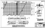
Chapter 2 - Construction of Ultra-Thin WhitetoppingUS 72 Westbound at the intersection with Hinton Street was selected for the locationof the Ultra-Thin Whitetopping (UTW) test section. Construction of the section tookplace in both the right and left thru lanes in phases and extended 265’ behind thestopbar and 209’ ahead of the stopbar for a total length of 474’ in each thru lane. A3” concrete thickness was constructed with the ends of each section being thickenedto 6” in depth. Sawcut panels were cut on 3’x3’ centers.Figure 9 – Elevation view of UTW sectionPreconstruction pavement condition measurements for the proposed UTW sectionyielded an average rut depth of 1.43”, an average skid friction number (SN) of 34.5,an average PI (0.2” Blanking Band) of 167 inches/mile, an average PI (Zero Blanking Band) of 215inches/mile and an average IRI of 584 inches/mile.APAC – Northern Division using their Corinth, Mississippi operations were selectedto perform the milling and construct the UTW. B & B Concrete of Tupelo,Mississippi, batched the concrete to the site from their plant in Corinth, Mississippi.On April 3, 2001, the inside thru lane of the UTW section was milled with a targetdepth of 3”, and an additional 3” depth for 6” total milled at either end. Due to thenature of the milling procedure, achieving an exact depth of 3” throughout our sectionwas impossibility.On April 4, 2001, the construction of the inside thru lane with UTW began. Thecontractor chose to employ a vibratory manual screed for the construction of thepavement. A 5000 psi air-entrained concrete mix containing fibrillatedpolypropylene fibers was utilized for the project. See Appendix C for the completeconcrete mix design and Appendix D for MDOT Special Provisions related to theconstruction of the UTW section.The first concrete truck arrived at the project site at approximately 10:30am on asunny but cool day with temperatures ranging in from 55 degrees Fahrenheit at thebeginning of the pour, to 60 degrees at completion. A total of 66 cubic yards ofconcrete was utilized in phase I of the 474’ long section and paving was completed in5 ½ hours.During the pouring of concrete, random samples were taken and the slump and aircontent were measured. The average slump was 4.5” and the average air content was5.5%. A complete listing of the slump and air content measurements appears in6
Appendix C. Cylinders were constructed from 2 trucks during the course ofconstruction. These cylinders were broken at 24 hours, 48 hours, 7 days and 28 days.A listing of the cylinder break results is also included in Appendix E.Once the concrete had achieved its initial “set”, a metal broom was used to achievethe transverse tined finish. This was performed on a section approximately 2 hoursbehind the paving screed.After the pavement had been transverse tined, the contractor applied a water basedwhite pigmented concrete curing compound.For a 3” thick UTW, it is common practice to saw cut 3’ x 3’ panels in the “green”concrete. This project adhered to that practice. Two “Soff-cut” concrete saws wereutilized and began sawing the panels at approximately 3:00 pm about 4½ hoursbehind the paving operation.The concrete industry has recommended that plastic spacers be utilized at locationswhere sawcuts cross. The first cut is made and at the location where the second cutwill cross the first, a plastic spacer is inserted in the fresh cut. This prevents the jointfrom closing up when the second cut is made. The UTW section employed thesespacers at every cross cut.Construction of the inside thru lane was completed at 11:00 pm.The newly constructed UTW was allowed to cure for approximately 48 hours andwas opened to traffic at 12 pm on April 6, 2001.On April 9, 2001, the outside thru lane of the UTW section was milled with a targetdepth of 3”, and an additional 3” depth for 6” total milled at either end.On April 10, 2001, construction of the outside thru lane with UTW began. Thecontractor utilized the same construction methods as had been employed on the insidelane one week previous. The same concrete mix was used for both lanes.The first concrete truck arrived at the project at 9:00am on a sunny and warm daywith temperatures ranging from 70 degrees F at the beginning of the pour, to 86degrees F at completion of the pour. A total of 63 cubic yards of concrete wasutilized in phase II of the 474’ long section and paving was completed in 5½ hours.Samples were taken and the slump and air content measured. The average slump was5.25” and the average air content was measured to be 4.9% in the concrete utilized inphase II. A complete listing of all slump and air content measurements appears inAppendix C. A list of all cylinder break results from phase II of construction is alsoavailable in Appendix E.Once again a metal broom was used to achieve the transverse tined finishapproximately 2 hours behind the paving screed.7
After the white pigmented concrete curing compound had been applied to the freshlytined concrete surface, sawing of the 3’ x 3’ panels began. The two “Soff-cut”concrete saws began sawing panels at 1:30 pm which was approximately 4½ hoursbehind the paving screed.The cross cut spacers were utilized for sawing in phase II of the UTW section.Construction of the outside thru lane was completed at 7:30 pm.The newly constructed UTW in the outside thru lane was allowed to cure forapproximately 48 hours and was opened to traffic at 12 pm on April 12, 2001.A complete listing of the California type profilograph, high speed profiler and surfacefriction data for the UTW section appears in Appendix C.Cost data for the construction of the UTW section appears in Appendix I.8
Figure 10 – Milling of the existing asphalt prior to construction of each test sectionFigure 11 – Pouring concrete at the Ultra-Thin Whitetopping test section9
Figure 12 – Whitetopping is given a transverse tined finish with a metal broomFigure 13 – White pigmented curing compound is applied to fresh concrete10
Figure 14 – 3’x3’ panels are sawcut into the “green” concreteFigure 15 – Plastic spacers are used at the cross cuts to achieve a clean cut11
Chapter 3 - Construction of <strong>Resin</strong> <strong>Modified</strong> <strong>Pavement</strong><strong>Resin</strong> <strong>Modified</strong> <strong>Pavement</strong> (RMP) is a composite paving material that combines the rutresistance of a concrete pavement with the lower initial cost of an asphalt pavement.An open graded 2” thick lift of hot-mix asphalt is constructed with approximately 30%air voids. After the mat has been allowed to cool to ambient temperature, a highlyfluid cement grout is poured onto the mat. The grout must penetrate the entire 2”depth of the open graded asphalt and fill all of the internal voids in the mat.This paving technique was developed in France in the 1960’s and has been widelyutilized throughout Europe. To date most of the UTW in the United States have beenpavements constructed for military applications.The United States Army Center for Public Works published a “User’s Guide: <strong>Resin</strong><strong>Modified</strong> <strong>Pavement</strong>” in 1996 which is included in Appendix G. This document wasutilized as a guide during the construction of Mississippi’s RMP test sections.In addition, the Mississippi DOT contracted the services of Dr. Randy Ahlrich. Dr.Ahlrich is an employee of Burns, Cooley and Dennis, a Jackson MississippiGeotechnical engineering firm. Dr. Ahlrich gained extensive experience with RMPduring his former employment with the United States Army Engineer WaterwaysExperiment Station.Since the Mississippi DOT has no previous experience with the RMP pavement, it wasdecided that a 100’ x 12’ test strip should be constructed off site in a “mill and fill”application as would be utilized on site. A location at the APAC – Corinth asphaltplant was utilized for the test section.On April 2, 2001 construction of the RMP test strip began. The strip was milled to theapproximate 2” depth at 8:00 am. At approximately 2:00 pm on a sunny 78 degree Fafternoon, the open graded mix was laid into the freshly milled section. It requiredapproximately 15 tons of asphalt to construct the strip. The mat temperature wasapproximately 290 degrees F at laydown. After approximately 1 hour, when the mattemperature had reached 140 degrees F, a small 2-ton steel wheel roller in static modemade one roller pass on the mat to smooth any imperfections in the mat.After examining the gradations from the truck samples that were taken from the teststrip material, it was determined not to accept the first test strip. For unexplainedreasons the mix gradation had “fined” during production with too much materialpassing the #4 sieve, hence our air voids in the mat were at the 25% minimum limit.Rather than risk attempting to add the grout to the strip, APAC was told they mustremove the mat, make adjustments to the gradation to “coarsen” the mix and place themat again.12
On April 5, 2001, construction of RMP test strip 2 began. At 9:20 am on an overcast63-degree F morning, the open graded mix was laid into the milled section. Onceagain 15 tons of asphalt was required to construct the test strip. For test strip 2 the mattemperature was approximately 240 degrees F at laydown. After approximately 20minutes, when the mat temperature had reached 140 degrees F, the small 2-ton steelwheel roller was utilized in static mode to smooth any imperfections in the mat.The gradations were examined from the truck samples that were taken from the teststrip material and they were well within the Job Mix Formula tolerances. The mat wasdeemed acceptable and was covered with a tarp to prevent any excessive moistureinfiltration until the grout could be added.On April 9, 2001 after a three day delay due to mechanical difficulties with the fly ashsilo auger at B & B Concrete’s Corinth plant, the cement grout was batched at 11:00am. It is important to note that prior to batching grout into cement trucks, care shouldbe taken to ensure that the drum of the truck is clean. Contamination of the grout withother material can be detrimental to the grout. During the plant batching process for a4 cubic yard load of grout, initially half of the water or 1550 gallons was added to thecement truck. Next, the Silica Sand, 2280 lbs dry weight is added to the truck. Afterthe sand has been added, 4556 lbs of Type 1 Cement is added to the truck. Next, theType F Fly Ash, 2280 lbs, is added. And finally the remaining water with theexception of ten gallons was added. It is important to note that during loading andtransport of the mixture the drum of the cement truck must be agitating. For thisproject, the resin additive PL7, was added to the truck at the project site. The concretetruck arrived at the project site at 11:30 am on a sunny 76-degree F morning. A smallpump was used to pump the PL7 from its 55-gallon drum into the concrete truck.After all of the additive had been pumped out of the drum, the remaining 10 gallons ofwater was used to rinse out the drum and pumped into the concrete truck. The groutmixture should undergo the maximum rotations of the concrete truck for no less than10 minutes to insure that the PL7 is thoroughly mixed. For construction of the RMPtest strip 2 at APAC-Corinth’s plant, only 3 cubic yards of the grout was batched.Therefore, all of the mixture quantities detailed in the previous paragraph werereduced by 25%.At 11:50 am after adding the PL7 and mixing for 10 minutes, the grout was ready tobe poured into our mat of open graded asphalt. Before pouring the viscosity of thegrout must be checked using a Marsh flow cone. The Marsh cone is used to measurethe length of time it takes for 1 liter of grout to flow through the cone. Too high of aflow time would mean that the grout is too viscous and might not penetrate the opengraded asphalt layer completely. If the flow time was too low, the grout may not gainthe strength required. For this project an acceptable flow time is between 7 and 10seconds. The flow of the grout that was used in RMP test strip 2 was checked andtimed out to 8.72 seconds which was acceptable.13
Using 2” grout cube molds, six grout cubes were made to verify the strength of thegrout. The compressive strength of these cubes would be checked at 48 hours. Thegrout should have a compressive strength of at least 2000 psi. after 48 hours.The grout was poured into the RMP test strip 2 mat. Hand held squeegees are used to“push and pull” excess grout material to under-saturated areas. Due to the lowviscosity of the grout, care must be taken at the edges of the mat to insure thatsignificant amount of grout is not lost due to grout overflowing the mat. During thedistribution of grout material, a three-ton roller in vibratory mode is driven over thegrouted mat. The vibration of the roller helps the grout to penetrate the entire 2” depthof the open graded asphalt mat. Air bubbles should be visible behind the roller wheelsindicating that the air voids in the asphalt are being saturated with the grout. After themat has been fully saturated with grout, a push broom is used to get the final surfacetexture of the grouted mat.Two days later on April 11, 2001, 4” diameter cores were taken in the RMP test strip 2mat. A visual inspection of the cores was made to determine if the grout hadpenetrated the entire depth of the open graded asphalt mat. If more than 95% of thevoids appear to be saturated with grout, then the grout has sufficiently penetrated themat. All of our cores appeared to have over 95% penetration and the RMP test strip 2was considered a success. With the test strip constructed and approved, plans weremade to begin construction of our two RMP test sections on US 72 the followingweek.Also on April 11, our 2” grout cubes were broken in the laboratory to determine theircompressive strength. The cubes met the 2000 psi compressive strength after 48 hoursrequirement. A complete listing of cube breaks appears in Appendix F.On April 16, 2001, with an air temperature of 70 degrees F, the 2” thick open gradedHMA mat was laid in the inside thru lane at each of our RMP test locations on US 72Eastbound. The hot-mix asphalt arrived at the site with a temperature ofapproximately 220 degrees F and paving began at approximately 5:20 pm at US 72and Cass Street and took 20 minutes to pave the 365’ x 12’ area. Once the paver hadmoved the 3000’ to the test location at US 72 and Hinton Street, paving resumed at6:10 pm and took approximately 25 minutes to pave the 435’ x 12’ area at theintersection with Hinton Street. A complete listing of mat temperatures and pavingtimes are provided in Appendix F. Samples were taken from two trucks of hot-mixasphalt at the plant and gradations and asphalt cement content of the mix was verified.A listing of those results appears in Appendix F.During the night a cold front moved through the area and on a cold morning on April17, 2001 with temperatures near 40 degrees F, the cement grout was poured into the 2”thick open graded mix at both of the RMP test locations on US 72 Eastbound.On the morning of April 17, 2001, prior to the arrival of grout, nuclear density gaugereadings were performed both test sections to verify the target 30% air voids. Acomplete listing of the nuclear density gauge results appears in Appendix F.14
Batches of cement grout arrived on site in 4 cubic yard quantities per truck. Theidentical mixing technique that was detailed during the construction of the test strip 2at APAC’s plant was utilized during construction of the test sections. Once again, thePL7 additive was pumped into the trucks on site and mixed vigorously for 10 minutesbefore being poured into the open graded mat.Grout began to be poured at the intersection with Hinton St. at approximately 9:20 am.Prior to utilizing any truck load of grout, the flow time was checked using the Marshfunnel as detailed during the construction of the test strip. A complete listing ofproduction rates and Marsh funnel flow times appears in Appendix F. As with the teststrip, 2” grout cube molds were utilized to construct six grout cubes with which tocheck the 48 hour compressive strength of the grout. Once the flow time was checked,the grout was poured onto the open graded asphalt mat. As with the construction of thetest strip, hand held squeegees were used to “push and pull” excess grout material tounder-saturated areas. Due to the low viscosity of the grout, care must be taken at theedges of the mat to insure that a significant amount of grout is not lost due to the groutoverflowing the mat. Since the grout is being added to a 2” thick mat which has beeninlayed into the existing asphalt, the only grout that could be lost due to overflow is onthe surface of the mat and at the ends of the section. To prevent seepage at the ends ofthe section, a temporary wedge of cold mix asphalt was constructed at each end of thesection. During the distribution of grout material, a three-ton roller in vibratory modeis driven over the grouted mat. The vibration of the roller helps the grout to penetratethe entire 2” depth of the open graded asphalt mat. Air bubbles should be visiblebehind the roller wheels indicating that the air voids in the asphalt are being saturatedwith the grout. After the mat has been fully saturated with grout, a push broom is usedto get the final surface texture of the grouted mat.Each 4 cubic yard truck of grout would yield enough grout to fill approximately 125linear feet of the 12’ wide x 2” thick open graded asphalt mat. Each 55 gallon drum ofthe PL-7 additive would produce 4 cubic yards of grout and only 12 drums of the PL-7were available for this experiment. During construction of the test strip three quartersof one drum of PL-7 was utilized to produce the 3 cubic yards of grout required for thetest strip. This left 11.25 drums available for construction of the two test sections onUS 72. Since the additive is very expensive and the quantity that was available for thisexperiment was limited, attention to production was very high to determine if enoughadditive was available to complete the sections.During construction of the US 72 inside thru lane at Hinton Street, it was decided toterminate construction of the section 125’ short of the 435’ design length. This wouldprovide more of a “safety factor” since the amount of PL-7 available was limited.Thus the section at Hinton Street was now 310’ in length.Construction of the 310’ x 12’ RMP section (inside thru lane) at Hinton Street wascompleted at approximately 11:45 am. Since the construction of the inside thru lane atthe intersection with Hinton Street had required approximately 10 cubic yards of groutand the grout was being batched in 4 cubic yard loads, there was approximately 215
cubic yards remaining in the last truck upon completion of the section. This groutneeded to be utilized to begin construction of the inside thru lane at the intersectionwith Cass Street. It is important to point out that during construction, the concretetruck must be continually agitating the grout mixture to prevent it from prematurelythickening. Should thickening of the grout occur, it would be detrimental to achievingfull penetration of the grout into the 2” thick open graded mat of asphalt. Therefore, itwas important to utilize this grout as quickly as possible before the grout could “setup”.Approximately 30 minutes later with the remaining 2 cubic yards of grout undergoingthe maximum revolutions that the concrete truck was capable of, the second testsection at Cass Street was ready for grouting. The Marsh funnel was used to check theflow of the 2 cubic yards and it timed out at 9.66 seconds which was acceptable andgrouting of the intersection at Cass Street began at approximately 12:15pm.After a long cold day with wind chills near the freezing mark, construction of the 365’x 12’ section at the intersection of Cass Street was completed at approximately2:15pm. Each section received a dusting of a water based white pigmented concretecuring compound.It is important to point out that throughout the day, each 4 cubic yard load of groutyielded approximately 125’ of production. However, the final truck of the day at theintersection of Cass Street yielded 175’ of RMP pavement. This will be a criticalpiece of information as time progresses.During the night, the temperature in Corinth dropped to 32 degrees F. The nextmorning (4/18) when we collected our grout cubes, we were disturbed by what wasdiscovered. Apparently the severe cold had caused excessive shrinkage of the groutand each cube had imploded on itself leaving them impossible to perform acompressive strength test on and basically useless to the study. An inspection of thepavement sections troubled us as well. The grout appeared to be “powdering up” onthe surface as you could lightly scrape the surface and produce a powdery residue.This condition had not appeared at the test strip and apparently the severe cold hadslowed down the curing of the grout tremendously. After consulting with Dr. Ahlrich,it was decided that a “wait and see” approach should be taken to determine if as thepavement warmed whether the grout would begin undergoing it’s cementitiousreaction once again. During the day on April 18 the temperature warmed toapproximately 55 degrees F.On April 19, 2001, the pavement surface was inspected once again and the powderingcondition that had been observed on the previous morning was not evident and thegrout appeared to be gaining strength. Our entire research team gave a collective sighof relief. Original plans called for coring the sections on Thursday April 20, 2001 andshould we achieve the required visual grout penetration in the cores, opening the laneto traffic on Friday April 21. However, based on the slow curing and the lack of groutcubes to verify strength, it was decide to continue to keep the lane closed over theweekend and core the sections on the morning of Monday April 23. Assuming coring16
showed no problems, open the lane to traffic on the afternoon of April 23 rd , whichwould allow the grout 6 days for curing.On April 23, 2001, the two sections were cored. In the section at the intersection withCass Street the mystery as to why one concrete truck had yielded 175’ of production asopposed to 125’ everywhere else was solved. When we cored this area, the coresrevealed that the grout had “capped off” and not sufficiently penetrated the entire 2”thickness of the mat. Therefore we were able to get more linear production in this areathan anywhere else. After coring to verify the extent of the “capping”, it wasdetermined that the last 75’ of the section must be milled and removed. Thus thesection at Cass Street arrived at it present dimension of 290’ x 12’. All other coring inboth sections yielded satisfactory grout penetration. After the failed 75’ section hadbeen removed, the sections were opened to traffic on the afternoon of April 23, 2001.On April 24, 2001, construction of the RMP in the right thru lane at each test sectionbegan. Throughout the construction of the right lane the weather was much warmerand low temperatures failed to drop below 50 degrees F. Identical constructiontechniques used during the construction of the left thru lane portion of the sectionswere employed throughout the construction of the right thru lane sections. Data takenat the lab from the two truck asphalt samples appears in Appendix F. Nuclear densityreadings taken on the mat prior to incorporation of the grout appears in Appendix F.Grout was incorporated into the open graded asphalt on the morning of April 25, 2001.The temperature when work began was 52 degrees F and warmed to 67 degrees F bythe time construction had completed. Once again flow times were checked and groutcubes prepared. A full listing of production rates and Marsh flow times appears inAppendix F.Since the temperatures during construction of the right thru lanes were much higherthan during the construction of the left thru lanes successful grout cubes were preparedand broken in the lab. A listing of the cube compressive strengths appears inAppendix F.Due to the warmer weather, the “powdering” effect that appeared during the curing ofthe left thru lane sections failed to materialize during curing of the right thru lanes. Itwas still decided to be conservative and wait to open the lanes to traffic until April 30,allowing the grout 5 days to cure.On April 30, the right thru lanes were cored to verify grout penetration. This time nocapping of the material was discovered and both test sections were opened to traffic asbuilt.A complete listing of the California type profilograph, high speed profiler and surfacefriction data for the RMP section appears in Appendix F. Cost data for theconstruction of the RMP sections appears in Appendix I.17
Figure 16 – APAC Corinth “drum” plant which produced both the PG 67-22 opengraded mix for the <strong>Resin</strong> <strong>Modified</strong> <strong>Pavement</strong> and the PG 82-22 dense graded mixFigure 17 – Paving the PG 67-22 open graded mix for the RMP test section18
Figure 18 – Close up of the surface of the 2” thick open graded matFigure 19 – Open graded mix is subjected to one pass with a 1½ ton roller in staticmode @ approximately 150 degrees F to “seat” the aggregate19
Figure 20 – B & B Concrete Corinth plant which supplied the grout for the RMPFigure 21 – PL7 latex additive is added to the grout at the site20
Figure 22 – Close up of PL7 latex additiveFigure 23 – Flow time of the grout is checked with a Marsh cone21
Figure 24 – 2” mortar cubes are made to test the grout strengthFigure 25 – Grout is poured onto the open graded asphalt mat22
Figure 26 – Using a 3 ton roller in vibratory mode, the grout is forced to penetrate theentire thickness of the 2” open graded asphalt matFigure 27 – Excess grout is worked to under grouted areas using squeegees23
Figure 28 – “Working the grout”Figure 29 – Excess grout is pulled forward24
Figure 30 – Finished product the next morning (US 72 & Hinton St. looking east)Figure 31 – Cores are taken to insure 95% saturation of grout25
Figure 32 – Entire mat did not get saturated in some areas (1” capping of grout)Figure 33 – Milling up of 75’ x 12’ area that failed to achieve full grout penetration26
Chapter 4 - Construction of Performance Graded 82-22 Polymer <strong>Modified</strong> HotMix AsphaltOnce MDOT granted approval to the contractor’s proposed mix design (see AppendixH) for the PG 82-22 HMA, a 450’x 24’ test strip was constructed on June 12, 2001 toestablish rolling patterns and density gauge biases. The paving train consisted of aCraftco Accupave Windrow propelled by a Cat 966C, a Lincoln Shuttle Buggy, aBlaw Knox paver and 2 Cat CB634C 15 ton steel wheel rollers.The liquid AC used in the hot-mix was modified with a Styrene Butydene Styrene(SBS) polymer to achieve the PG 82-22 grade and was supplied by Ergon Asphalt &Emulsions, Inc., Memphis, Tennessee terminal. It should also be noted, that MDOTstandard practice is to include 1% hydrated lime in all our asphalt mixes to serve asan anti-strip agent. The PG 82-22 mix involved in our research did not deviate fromthat policy.For construction of the test strip, hot-mix asphalt left the plant at approximately 345degrees F. Temperatures behind the paver averaged 340 degrees F. A rolling patternwas established using six passes with a 15 ton roller in vibratory mode and onefinishing pass in static mode. Attached in Appendix H is a complete listing of alldensities both gauge and core verified gradations, SGC air voids and AC contents.Three gyratory pills were compacted to approximately 7 % air voids using mixmaterial and run in the department’s Asphalt <strong>Pavement</strong> Analyzer (APA) dry andsubjected to 8000 cycles of 100 psi hose pressure at 147 degrees F. The pills averagedepth of rut following the test was 0.10 inches (2.55 mm). The complete results ofthe APA testing can be found in Appendix H.Our Research section would consist of 2 – 2” thick lifts of 12.5mm NominalMaximum Aggregate Size (NMAS) PG 82-22 hot mix asphalt. A chert gravel &limestone blend was utilized for the mix. MDOT policy currently prohibits the use ofmore than 30% limestone in surface course asphalt mixes due to concerns aboutpolishing of some limestone mixes and the subsequent lack of friction resulting fromthat polishing. This mix adhered to that limitation and utilized only 30% limestoneaggregate. The test strip would serve as the lower lift of our research section locatedon U.S. 72 Westbound at the intersection on Cass Street.On June 15, 2001 the surface lift of the left thru lane of our 450’ research section waspaved. Temperatures of the mat directly behind the paver averaged approximately305 degrees F. See Appendix H for the surface mat temperatures. Attached inAppendix H is a complete listing of all densities both gauge and core verified,gradations, SGC air voids and AC contents from the surface of the left thru lane ofthe research section.On June 18, 2001 the surface lift of the right thru lane of our 450’ research sectionwas paved. Temperatures of the mat directly behind the paver averagedapproximately 305 degrees F. See Appendix H for the surface mat temperatures.27
Attached in Appendix H is a complete listing of all densities both gauge and coreverified gradations, SGC air voids and AC contents from the surface of the left thrulane of the research section.Unfortunately during construction of the right lane of our research section, thebreakdown roller experienced mechanical difficulties. Due to the high amount oftraffic in the area, approximately 10 vehicles drove on the fresh mat of asphalt beforethe breakdown roller could begin compacting the section. The traffic “scarred’ themat and the rollers were unable to remove all of the initial rutting due to the earlytraffic. After construction of the right lane, manual rut measurements were taken andthe rutting due to the early traffic averaged 0.09” in the left wheelpath and 0.04” inthe right wheelpath. The entire list of manual rut measurements that were collectedupon completion of the research section are available in Appendix H.A complete listing of the California type profilograph, high speed profiler and surfacefriction data for the PG 82-22 hot mix asphalt section appears in Appendix H.Cost data for the construction of the PG 82-22 section appears in Appendix I.Figure 34 – PG 82-22 dense graded HMA being dumped ahead of Windrow device28
Figure 35 – Paver equipped with “shuttlebuggy” for PG 82-22 pavingFigure 36 – Breakdown rolling (note scarring from traffic getting on the fresh mat)29
Figure 37 – Finish rolling30
Chapter 5 – Conclusions from Construction and Early PerformanceUltra-Thin WhitetoppingAs the data in Table C7 of Appendix C indicates, the smoothness of the Ultra-ThinWhitetopping test section is less than satisfactory. Undoubtedly this amount ofroughness will impact the service life of the pavement. For future projects utilizingUltra-Thin Whitetopping, adequate smoothness incentive/disincentive specificationsshould be utilized to insure proper care and construction techniques are employed by thecontractor. One step in the right direction would be to disallow the use of small “bull”floats for the finishing of the concrete surface.<strong>Resin</strong> <strong>Modified</strong> <strong>Pavement</strong>It cannot be stressed enough that care must be taken to insure proper quality control is inplace to successfully construct the <strong>Resin</strong> <strong>Modified</strong> <strong>Pavement</strong>. The gradations of the opengraded asphalt mix must be carefully controlled to insure the target 30% air void level isobtained. Should the mat have less than the target 30%, the ability of the grout topenetrate the entire 2” thickness is compromised.The grout must be agitated continuously once the PL7 latex additive has been introducedinto the mix. If proper agitation is not provided, the grout will become too viscous,which will hamper its ability to penetrate the entire 2” thickness of the mat.Planning quantities of grout that will be needed are difficult to calculate. Due to thenature of the pavement system, there are many variables which influence the amount ofgrout that will be required for a project. If air voids vary from the target 30%, the amountof grout required to fill the open graded mat will increase or decrease. On inlaysituations, if the milling depth varies and the thickness of the open graded asphalt matvaries, the quantity of grout required will also change.Since the PL7 latex additive is so expensive (approximately $1000 per 55 gallon drum)and it is imported, a limited amount of PL7 was available for this project. Attention togrout usage must be monitored during construction. Measures should be taken to insurethat too much grout is not wasted by overflowing the mat. During this project when itappeared that grout usage was higher than planned, 225’ of the <strong>Resin</strong> <strong>Modified</strong> <strong>Pavement</strong>test section was eliminated to insure that the quantity of available PL7 would not beexhausted prior to the completion of the test sections.The difficulty of constructing this pavement system is best exemplified by this project.Even with all of the above listed “attentions to detail” provided during construction, therestill was a 75’ section of the pavement that had to be removed due to a lack of groutpenetration of the mat. For an unexplained reason, a 75’ section of one of the <strong>Resin</strong><strong>Modified</strong> <strong>Pavement</strong> test sections “capped off”, with only approximately the top 1” of the2” thick mat receiving the proper amount of grout. A review of the air voids in the mat ofthis area and the grout flow times don’t indicate any problems. The same constructiontechniques that were employed in the successfully constructed portions of the test section31
were also utilized in the 75’ failed area. The answer as to why this happened remains amystery.Should temperatures during construction and curing of the <strong>Resin</strong> <strong>Modified</strong> <strong>Pavement</strong>drop below 50 degrees F, additional curing time will be required for the grout to obtainits design compressive strength. A rule of thumb is that no less than 72 hours of above50 degree F temperatures should be provided for the grout to cure. Even then, groutcubes should be constructed to verify the compressive strength of the grout beforeopening the <strong>Resin</strong> <strong>Modified</strong> <strong>Pavement</strong> to traffic.Precipitation can also be a factor in the construction of the <strong>Resin</strong> <strong>Modified</strong> <strong>Pavement</strong>. Itis critical that moisture does not enter the open graded asphalt mix prior to the addition ofthe grout. If it does rain before the addition of grout, the voids in the mat must be free ofmoisture before the grout can be added.One additional point of note concerning the <strong>Resin</strong> <strong>Modified</strong> <strong>Pavement</strong> is early skidperformance. A review of tables F28 & F29 in Appendix F indicates that initial skidperformance (values in the low to mid 20’s) is less than satisfactory. However, as trafficbegins to wear the top film of grout off the section and aggregate from the open gradedasphalt mat is exposed, the skid numbers begin to improve to adequate levels. This earlylack of surface friction could be a safety issue, especially in high speed trafficapplications.Performance Graded 82-22 AsphaltNormal quality HMA construction techniques should be utilized when performing PG82-22 paving. When utilizing highly modified asphalt, the mix must arrive at the projectwith a high enough temperature to insure proper densification during rolling operations.For this project, APAC’s Corinth plant was only located approximately one mile from thetest section, therefore temperature was not a problem.32
Chapter 6 – Long Term PerformanceEach test section was monitored over a five year period (April 2001- April 2006). Datacollected included skid resistance, rut depth, IRI, and pavement distress surveys.<strong>Pavement</strong> distresses were identified using the LTPP distress identification manual and thefollowing distresses were identified during this project:• Transverse Cracking• Longitudinal Cracking• Patching• RuttingOnce identified and measured, total deduct points were calculated using curvespreviously developed for MDOT. It should be noted that distresses for each of the testsections were normalized to a 500 foot section length for analysis due to the fact thatMDOT’s deduct curves are based on a 500 foot section length.A pavement condition rating (PCR) was calculated using both IRI and distress ratings.All long term roughness and rutting data was collected using an International CyberneticsCorporation full size profiler model MDR 4086L3.The following is a summary of the long term data for each test section.Ultra-Thin WhitetoppingLong term data for the Ultra-Thin Whitetopping test section is given in Table C10 ofAppendix C.Skid resistance performance was good for the Ultra-Thin Whitetopping test section, withno average values falling below 40. A value of 35 or better is desired on all MDOTmaintained roads.Collection of the rut values for the Ultra-Thin Whitetopping produced some minimalaverage rut values. It was determined however that these values were due to the lasers ofthe profiler reading the joints cut into the pavement and not due to actual rutting of thepavement.Test sections for the Ultra-Thin Whitetopping, as noted in the previous chapter, began inless than satisfactory condition with initial IRI values above 4. Those values weresignificantly higher than those of the other test sections. IRI values this high are normallyassociated with older pavements in need of repair, not new construction. A review of thedata shows that the condition of the pavement continued to deteriorate over the life of theproject.The substantially high IRI values were most likely what produced the low pavementcondition rating (PCR) values. Initial PCR values for the inside and outside lane were65.9 and 54.6 respectively. MDOT suggests that four lane pavements with a PCR value33
of 72 or lower should be considered for rehabilitation. This means the Ultra-ThinWhitetopping test section was inadequate from the time of construction.Approximately two years into the project (2003), several Ultra- Thin Whitetoppingpanels began to crack and break apart. Broken panels were removed and replaced withconcrete containing a product called STRUX 90/40 fibers provided by GraceConstruction. STRUX 90/40 is a high performance synthetic structural fiber specificallyengineered to impart tight crack control as well as plastic shrinkage control. In 2007,MDOT maintenance crews informed us of their intentions to remove and replace theentire Ultra-Thin Whitetopping test section due to excessive failures. An example ofthese failures is shown in Figure C11 of Appendix C. It should be noted that some of thepanels replaced in 2003 experienced failure as well, meaning the added STRUX 90/40fibers did not make a significant difference. This can be seen in Figure C12 of AppendixC.<strong>Resin</strong> <strong>Modified</strong> <strong>Pavement</strong>Long term data for the <strong>Resin</strong> <strong>Modified</strong> <strong>Pavement</strong> test sections is provided in Tables F30and F31 of Appendix F.Early skid resistance was noted as a problem for the <strong>Resin</strong> <strong>Modified</strong> <strong>Pavement</strong> testsections. This problem improved within a few months, however by the fourth year (2005)skid values again fell near 30, a value well below MDOT’s recommended acceptablevalue of 35.A review of the long term <strong>Resin</strong> <strong>Modified</strong> <strong>Pavement</strong> data provided one significant result.There was no rutting observed in either test section throughout the duration of the project.Overall, the PCR values for the <strong>Resin</strong> <strong>Modified</strong> <strong>Pavement</strong> sections were acceptable. Thelone exception was the inside lane of Cass Street. This is most likely attributed to the IRIvalues for that lane being substantially higher than the other lanes in the test sections. Thehigher IRI values can most likely be attributed to improper care during construction toinsure smoothness of the pavement.It should be noted that <strong>Resin</strong> <strong>Modified</strong> <strong>Pavement</strong> is not a specific pavement category foruse in the deduct curves used by MDOT in PCR calculations. After consideration, it wasdecided that a <strong>Resin</strong> <strong>Modified</strong> <strong>Pavement</strong> behaved most like a continuously reinforcedconcrete pavement and therefore CRCP deduct curves were used for the PCR calculationsof the <strong>Resin</strong> <strong>Modified</strong> <strong>Pavement</strong> sections.Performance Graded 82-22 AsphaltLong term data for the PG 82-22 test section can be found in Table H17 of Appendix H.Skid resistance values for the PG 82-22 test section were adequate for the first few yearsof the study, but deteriorated by the fourth year (2005). At 28.1 and 28.5 for the insideand outside lane respectively, the values are well below the recommended value of 35.34
These values are of greater concern due to the test section being located at an intersectionwhere frequent braking occurs.Rut values for the PG 82-22 performed much the same as the skid resistance over time.Initially the values were good, however in year four (2005), the higher trafficked outsidelane showed an average rut value of 0.25 inches. It should be noted that those are averagerut measurements over the entire section. Visual observations showed that the ruts wereminimal at the beginning of the section and significantly worse closer to the intersection.The PG 82-22 mix provided a smooth surface as noted in the IRI values. This smoothsurface combined with few distresses allowed for a satisfactory PCR value throughout theduration of the project.35
Chapter 7 – ConclusionsUsing construction, performance, and cost data from these test sections; a head to headcomparison of each paving method can be made in order to assist the MississippiDepartment of Transportation in developing a paving strategy for highly traffickedintersections. For the comparison, each paving method will be ranked in severalcategories. The best paving option for each category will be given a value of 1, the nextbest will be given a 2, and the least desirable option will be given a 3. Once all categoriesare ranked, the pavement options will be totaled with the lowest total being ranked thebest option. These comparisons and results can be seen below in Table 1.CategoryEase ofConstructionTable 1- Comparison of paving methodsUltra-Thin <strong>Resin</strong> <strong>Modified</strong>Whitetopping <strong>Pavement</strong>PG 82-222 3 1Skid Resistance 1 3 2Rutting 2 1 3IRI 3 2 1PCR 3 2 1Cost 2 3 1Total 13 14 9The comparison above shows the PG 82-22 to be the best option. That result is supportedby the information gathered throughout this study.One issue affecting the PG 82-22 was rutting near the end of the study. This is an issuewith all asphalt pavements; however improvements continue to be made in Superpavemix designs to alleviate rutting. Also, the PG 82-22 section was constructed at about onethird of the cost of the other test sections, meaning the Ultra-Thin Whitetopping and the<strong>Resin</strong> <strong>Modified</strong> test sections would need to have three times the service life to accountfor the difference in cost. That was certainly not the case with the Ultra-ThinWhitetopping as it was removed and replaced in 2007 due to excessive failures.The <strong>Resin</strong> <strong>Modified</strong> pavement sections held up throughout the study, however thecomplexity and attention to detail in construction needed for this pavement to performsuccessfully makes it a less appealing option. This was evident because even in thecontrolled environment provided by this study, construction problems occurred with thecapping of grout before it fully penetrated the mat.36
After reviewing all available data for this study, the cost, performance, and ease ofconstruction makes the PG 82-22 the most reasonable choice for paving of MDOT’shighly trafficked intersections.37
APPENDIX ATRAFFIC DATA
Figure A1 – Design Traffic DataA-1
Figure A2 – Yearly Itemized <strong>Project</strong>ed Traffic DataA-2
Figure A3 – Year 2000 <strong>Project</strong>ed 24 hour turning movements for US 72 @ Cass StreetA-3
Figure A4 – Year 2020 <strong>Project</strong>ed 24 hour turning movements for US 72 @ Cass StreetA-4
Figure A5 – Year 2000 <strong>Project</strong>ed 24 hour turning movements for US 72 @ HintonStreetA-5
Figure A6 – Year 2020 <strong>Project</strong>ed 24 hour turning movements for US 72 @ Hinton StreetA-6
APPENDIX BPRECONSTRUCTION DATA
Table B1 – Preconstruction Rut Data for US 72 EastboundUS72 Eastbound @ Cass St. US72 Eastbound @ Hinton St.(Future <strong>Resin</strong> <strong>Modified</strong> Location)(Future <strong>Resin</strong> <strong>Modified</strong> Location)Ruts (1/16 th inch) Ruts (1/16 th inch)Station LWP RWP Station LWP RWP0+00 4 3 0+00 12 120+25 6 5 0+20 10 130+50 8 6 0+45 15 150+75 7 6 0+70 17 181+00 7 7 0+95 23 161+25 11 10 1+20 21 181+50 16 18 1+45 21 201+75 11 12 1+70 23 262+00 15 18 1+95 21 262+25 18 18 2+20 19 292+50 20 24 2+45 18 162+75 18 24 2+70 22 243+00 16 23 2+75 20 233+25 17 24 2+80 17 183+50 17 25 2+85 22 253+75 17 24 2+90 22 253+80 20 24 2+95 18 133+85 18 26 3+00 19 163+90 17 26 3+05 21 163+95 18 24 3+10 15 134+00 17 16 3+15 15 124+05 19 19 3+20 13 104+10 18 14 3+25 16 134+15 18 19 3+30 15 154+20 16 19 3+35 17 124+25 17 18 4+35 10 84+30 16 184+35 15 174+65 14 17B-1
Table B2 – Preconstruction Rut Data for US 72 WestboundUS72 Westbound @ Cass St. US72 Westbound @ Hinton St.(Future PG 82-22 HMA Location)(Future Ultra-Thin WhitetoppingLocation)Ruts (1/16 th inch)Ruts (1/16 th inch)Station LWP RWP Station LWP RWP0+00 12 10 0+00 15 260+25 14 12 0+15 21 250+50 15 13 0+40 20 340+75 16 15 0+65 18 301+00 13 12 0+90 18 181+25 17 11 1+15 22 321+50 21 15 1+40 22 281+75 26 20 1+65 28 402+00 19 14 1+90 26 402+25 28 17 2+15 26 402+50 30 20 2+40 28 402+75 24 15 2+45 28 403+00 28 18 2+50 28 353+25 30 16 2+55 26 403+50 32 24 2+60 28 343+55 32 28 2+65 24 283+60 24 22 2+70 22 353+65 25 23 2+75 24 323+70 21 24 2+80 19 213+75 19 20 2+85 21 323+80 28 20 2+90 24 353+85 20 12 3+15 16 183+90 16 16 3+40 16 243+95 18 14 3+65 13 124+00 16 10 3+90 11 144+45 13 7 4+74 9 16B-2
Table B3 - Preconstruction Friction Data Taken in Outside Lane at each location onMarch 30, 2001Location Skid No Avg Speed (mph) Temp (F) Time (CST)US 72E @ Cass St. (Future RMP) 31.5 41.3 53 5:33 AMUS 72E @ Cass St. (Future RMP) 35.5 39.2 53 5:33 AMUS 72E @ Cass St. (Future RMP) 32.5 43.2 55 5:42 AMUS 72E @ Cass St. (Future RMP) 35.8 41.1 55 5:42 AM33.8US 72E @ Hinton St. (Future RMP) 33.7 38.2 60 5:36 AMUS 72E @ Hinton St. (Future RMP) 34.8 41.7 60 5:36 AMUS 72E @ Hinton St. (Future RMP) 32.0 39.6 59 5:44 AMUS 72E @ Hinton St. (Future RMP) 35 43.7 59 5:44 AM33.9US 72W @ Hinton St. (Future UTW) 32.0 40.2 59 5:38 AMUS 72W @ Hinton St. (Future UTW) 36.9 38.3 59 5:38 AMUS 72W @ Hinton St. (Future UTW) 32.0 40.8 57 5:45 AMUS 72W @ Hinton St. (Future UTW) 37.2 38.7 57 5:45 AM34.5US 72W @ Cass St. (Future 82-22 HMA) 32.2 40.8 60 5:40 AMUS 72W @ Cass St. (Future 82-22 HMA) 33.5 41.1 60 5:40 AMUS 72W @ Cass St. (Future 82-22 HMA) 33.0 40.1 55 5:47 AMUS 72W @ Cass St. (Future 82-22 HMA) 33.9 42.6 53 5:47 AM33.2Table B4 – Preconstruction Smoothness DataLocation IRI (mm/m) PI (0.2" Blanking Band) (in/mi) PI (Zero Blanking Band)(in/mi)US 72E @ Cass St. (Future RMP) 3.00 31.27 71.88US 72E @ Hinton St. (Future RMP) n/a n/a n/aUS 72W @ Hinton St. (Future UTW) 9.22 166.87 215.40US 72W @ Cass St. (Future 82-22 HMA) 3.99 56.20 93.79B-3
APPENDIX CULTRA-THIN WHITETOPPING DATA
Figure C1 – Ultra-Thin Whitetopping Concrete Mix DesignC -1
Table C2 – UTW Properties for Inside Lane Construction (April 4, 2001)Truck No Cubic Yds Sta. Begin Sta. End Slump (in) Air Content (%)1 8 0+00 0+45 4 1/2 3.12 5 0+45 0+75 5 7.63 6 0+75 1+10 4 64 6 1+10 1+50 n/a n/a5 6 1+50 2+00 4 5.36 6 2+00 2+50 n/a n/a7 6 2+50 3+00 n/a n/a8 6 3+00 3+50 5 5.59 6 3+50 4+00 n/a n/a10 6 4+00 4+45 n/a n/a11 6 4+45 4+74 n/a n/aTable C3 – Compressive Strength Properties of Inside Lane Constructed UTWTruck No 24 hour break 48 hour break 7 day break (psi) 28 day break (psi)(psi)(psi)1 2933 4357 5489 61241 2808 4198 5599 66506 2727 4379 5666 66326 2622 4665 5673 6501Average 2773 4400 5607 6477Table C3 – UTW Properties for Outside Lane Construction (April 10, 2001)Truck No Cubic Yds Sta. Begin Sta. End Slump (in) Air Content (%)1 6 0+00 0+30 6 5.52 6 0+30 0+75 5 4.33 6 0+75 1+15 n/a n/a4 6 1+15 1+60 4 1/2 4.55 6 1+60 2+15 5 1/2 4.26 6 2+15 2+60 n/a n/a7 6 2+60 3+25 5 5.98 6 3+25 3+65 n/a n/a9 6 3+65 4+25 n/a n/a10 6 4+25 4+55 5 1/2 4.911 3 4+55 4+74 n/a n/aTable C4 – Compressive Strength Properties of Outside Lane Constructed UTWC -2
Truck No 24 hour break 48 hour break 7 day break (psi) 28 day break (psi)(psi)(psi)1 3181 4050 5510 55901 3243 4347 4654 52795 3393 5132 5832 67355 3944 4944 6048 7175Average 3440 4618 5511 6195Table C5 – Thickness of Ultra-Thin Whitetopping Left Lane of US 72 @ HintonStreet(Note: thicknesses shown at each offset are in feet)Left Offsets RightStation 0' 3' 6' 9' 12' Avg. Thick0+00 0.51' 0.49' 0.52' 0.51' 0.51' 0.508'0+09 0.48' 0.49' 0.56' 0.55' 0.53' 0.522'0+18 0.28' 0.33' 0.33' 0.32' 0.30' 0.312'0+25 0.26' 0.28' 0.31' 0.32' 0.32' 0.298'0+50 0.27' 0.31' 0.31' 0.33' 0.33' 0.310'0+75 0.24' 0.27' 0.30' 0.33' 0.34' 0.296'1+00 0.22' 0.26' 0.29' 0.26' 0.25' 0.256'1+25 0.26' 0.28' 0.30' 0.27' 0.25' 0.272'1+50 0.25' 0.29' 0.31' 0.29' 0.28' 0.284'1+75 0.23' 0.29' 0.29' 0.29' 0.29' 0.278'2+00 0.25' 0.30' 0.33' 0.32' 0.32' 0.304'2+25 0.26' 0.31' 0.32' 0.31' 0.32' 0.304'2+50 0.24' 0.28' 0.30' 0.32' 0.31' 0.290'2+75 0.29' 0.29' 0.32' 0.31' 0.30' 0.302'3+00 0.26' 0.26' 0.28' 0.27' 0.27' 0.268'3+25 0.27' 0.32' 0.31' 0.27' 0.27' 0.288'3+50 0.26' 0.28' 0.29' 0.28' 0.29' 0.280'3+75 0.27' 0.29' 0.30' 0.30' 0.31' 0.294'4+00 0.26' 0.28' 0.28' 0.29' 0.30' 0.282'4+25 0.26' 0.29' 0.30' 0.30' 0.31' 0.292'4+50 0.27' 0.29' 0.31' 0.33' 0.33' 0.306'4+56 0.31' 0.31' 0.35' 0.35' 0.36' 0.336'4+65 0.49' 0.54' 0.55' 0.54' 0.56' 0.536'4+74 0.49' 0.54' 0.54' 0.52' 0.51' 0.520'Total Concrete Used Left Lane =63.9 cubic yardsC -3
Table C6 – Thickness of Ultra-Thin Whitetopping in Right Lane of US 72 @Hinton Street(Note: thicknesses shown at each offset are in feet)Left Offsets RightStation 0' 3' 6' 9' 12' Avg. Thick0+00 0.49' 0.52' 0.60' 0.50' 0.54' 0.530'0+09 0.52' 0.55' 0.61' 0.57' 0.65' 0.580'0+18 0.36' 0.40' 0.44' 0.43' 0.45' 0.416'0+25 0.29' 0.32' 0.37' 0.35' 0.41' 0.348'0+50 0.28' 0.30' 0.35' 0.37' 0.41' 0.342'0+75 0.28' 0.31' 0.39' 0.37' 0.42' 0.354'1+00 0.25' 0.26' 0.31' 0.30' 0.32' 0.288'1+25 0.26' 0.30' 0.29' 0.26' 0.25' 0.272'1+50 0.25' 0.26' 0.29' 0.24' 0.24' 0.256'1+75 0.24' 0.27' 0.29' 0.25' 0.25' 0.260'2+00 0.25' 0.26' 0.28' 0.25' 0.25' 0.258'2+25 0.28' 0.28' 0.29' 0.27' 0.25' 0.274'2+50 0.27' 0.28' 0.27' 0.29' 0.25' 0.272'2+75 0.28' 0.28' 0.30' 0.28' 0.28' 0.284'3+00 0.25' 0.27' 0.26' 0.24' 0.19' 0.242'3+25 0.25' 0.25' 0.28' 0.26' 0.25' 0.258'3+50 0.26' 0.26' 0.27' 0.23' 0.25' 0.254'3+75 0.27' 0.28' 0.28' 0.31' 0.32' 0.292'4+00 0.26' 0.26' 0.28' 0.25' 0.25' 0.260'4+25 0.25' 0.27' 0.27' 0.25' 0.27' 0.262'4+50 0.25' 0.30' 0.34' 0.28' 0.28' 0.290'4+56 0.27' 0.26' 0.25' 0.28' 0.28' 0.268'4+65 0.49' 0.34' 0.51' 0.42' 0.47' 0.446'4+74 0.48' 0.52' 0.53' 0.48' 0.50' 0.502'Total Concrete Used In Right Lane =62.7 cubic yardsC -4
Table C7 – UTW Smoothness Data collected in the Outside LaneDate Collected IRI (mm/m) PI (0.2" Blanking Band) (in/mi) PI (Zero Blanking Band) (in/mi)April 18, 2001 5.42* 100.03 148.28July 6, 2001 4.75** n/a n/aAugust 22, 2001 4.54** n/a n/aNote: PI data was collected in the right wheelpath using a “California Type”Profilograph with a 2’ low pass Butterworth filter.* - April 18 IRI was collected in the right wheelpath using MDOT’s ARRB TranportResearch Walking Profiler.** - July 6 & August 22 IRI is the average IRI of both wheelpaths collected usingMDOT’s High Speed “South Dakota Type” Profiler.Table C8 – UTW Friction Data collected in the Outside LaneDate Collected Skid No Avg Speed (mph) Temp (F) Time (CST)April 19, 2001 38.2 37.5 41 4:02 AMApril 19, 2001 36.8 39.2 44 4:05 AMApril 19, 2001 36.7 40.2 44 4:08 AMApril 19, 2001 35.6 40.3 44 4:10 AM36.8May 1, 2001 31.8 39.3 66 3:19 AMMay 1, 2001 33.0 39.3 66 3:25 AMMay 1, 2001 34.7 39.3 66 3:45 AM33.2July 6, 2001 32.6 38.1 n/a 3:57 AMJuly 6, 2001 33.2 38.3 73 4:02 AMJuly 6, 2001 34.0 38.3 73 4:07 AM33.3August 22, 2001 40.8 39.7 n/a 11:00 PMAugust 22, 2001 35.3 40.7 86 11:05 PMAugust 22, 2001 37.3 40.3 84 11:09 PM37.8December 4, 2001 44.2 39.2 59 12:08 AMDecember 4, 2001 43.5 40.5 60 12:13 AMDecember 4, 2001 44.8 39.1 60 12:19 AM44.2C -5
Table C9 – UTW Crack Mapping in the Outside Lane performed December 19, 2001(approximately eight months after construction)C -6
Table C10- Long Term Data for Ultra-Thin WhitetoppingHinton Street Ultra Thin WhitetoppingInside LaneOutside LaneYearIRI Avg.IRI Avg.SN Rut Avg. (in) (mm/m) PCR SN Rut Avg. (in) (mm/m) PCR2002 45 - - - 43.6 - - -2003 47.3 0 4.24 65.9 45.2 0 5.62 54.62004 - 0 4.29 65.5 - 0 5.46 55.62005 42.4 0 4.43 64.4 40.5 0 6.23 48.82006 - 0 4.5 63.7 - 0 6.31 46.7C -7
Figure C11- UTW Failure.Figure C12- Failure of Original and Replaced Panels.C -8
APPENDIX DMDOT UTW STANDARD SPECIFICATIONS
MISSISSIPPI DEPARTMENT OF TRANSPORTATIONDATE: 01/06/01SUBJECT:Thin Portland Cement Concrete <strong>Pavement</strong> (Whitetopping)PROJECT: <strong>Resin</strong> <strong>Modified</strong> <strong>Pavement</strong> <strong>Demonstration</strong> <strong>Project</strong> ~ Corinth, MSDescription. This work shall consist of the construction of portland cement concretepavement in accordance with Section 501 of the 1990 Edition of the Mississippi StandardSpecifications for Road and Bridge Construction, except as modified herein.Materials. Materials shall meet the requirements of the Division 700 and the followingsubsections:MaterialStandard Specification ReferencePortland Cement 701.01 and 701.02Admixtures 713.02Fly Ash 714.05Water 714.01Fine Aggregate 703.01 and 703.02Coarse Aggregate 703.01 and 703.03Curing Materials 713.01Fibers used shall be Fibrillated Polypropylene fibers. Fibrillated Polypropylene fibersshall be added at a rate of 3.0 lbs/yd 3 .Concrete slump shall not exceed 4 inches. An approved type F or G admixture shall beused. Admixtures shall be incorporated into the concrete in accordance with themanufacturer’s recommendations, subject to approval by the Engineer.Fly Ash may be substituted for cement at a maximum rate of 20% by weight and shall beincluded with the cement when determining the water/cement ratio, i.e. thewater/cementitious material ratio. Ground Granulated Blast-Furnace Slag (GGBFS) maybe substituted for cement at a maximum rate of 50% by weight and shall be included withthe cement when determining the water/cement ratio, i.e. the water/cementitious materialratio. Any GGBFS incorporated into the cement shall conform to the requirements ofSpecial Provision 907-714.Proportioning. The Ready-Mix Concrete Producer shall furnish the mix design.Concrete used in this application shall meet the following compressive strengthrequirement. The mix shall be designed to achieve a minimum compressive strength of2500 psi within 24 hours (field cured) after placement. The mix shall develop aminimum compressive strength of 3500 psi 14 days (standard cured) after placement.Verification of Mix Design. The Ready-Mix Concrete Producer shall furnish theEngineer with the required documentation indicating proper verification of the mixD-1
design. Documentation presented must indicate that the mix achieves the desired 2500psi in 24 hours. As a minimum, the Ready-Mix Concrete Producer shall submit to theEngineer the aggregate and concrete test results performed during the verification processby technicians certified by MDOT. Minimum tests for aggregates are specific gravity,moisture, and grading. The minimum tests for concrete are slump, air content,temperature, unit weight, yield, and compressive strength. For verification of the mixdesign used in this application the following requirements in Table 1 shall be met.Table 1CriteriaRequirementsSlump 4”Air Content 3% - 6%Yield ± 3%Compressive Strength 2500 psi in 24 hours(field curing); 3500 psi in 14 days(standard curing)Concrete Testing. The ready-mix concrete producer shall be responsible for testingaggregates, moisture, and gradation at the batch plant. MDOT will be responsible forfield testing of the concrete. A minimum of six test cylinders shall be made for eachcontinuous placement or every 100 cubic yards of concrete placed, whichever is less.Compressive strength testing shall be performed to accommodate traffic movements andto ensure proper strength of the concrete pavement. A compressive test is the average oftwo cylinders. Test cylinders cast to determine when the pavement can be opened totraffic shall be field cured next to the pavement until time of test. Test cylinders cast foracceptance of the concrete, 3500 psi in 14 days, shall be standard cured as per AASHTODesignation: T 23.Slump and air content tests shall be performed on the first load and then once every 50cubic yards. Yield shall be verified for each mix design during the first placement andevery 400 cubic yards of concrete placed on the project, with a minimum of one yield testper day. Concrete temperature shall be taken with each slump/air test, and each timecylinders are made. Due to the high early strength requirements, cooling precautionsshall be implemented to prevent concrete temperatures from exceeding 100°F. Amaximum concrete temperature of 95°F is required without cooling precautionsimplemented. No concrete shall be placed with temperatures exceeding 100°F.Acceptance of the concrete will be based on test results meeting the requirements ofTable 1 and other requirements herein specified. All concrete testing shall be performedby MDOT Certified Technicians.D-2
Construction Requirements.General. Concrete shall be placed and spread in an approved manner so as to distributethe concrete uniformly without segregation. The base shall be dampened just prior toplacement of the concrete. Additional placement requirements are provided inSubsection 501.03.13.Final finishing of the concrete pavement surface shall be in accordance with Subsection501.03.17 of the Standard Specifications. The surface of the concrete pavement shall betransverse tined in accordance with Subsection 501.03.18.4 of the StandardSpecifications with two exceptions: the uniform parallel grooves perpendicular to thecenterline of the pavement may be up to 1 inch on centers, and the drag finish is notrequired.Sawing of the joints shall commence as soon as the concrete has hardened sufficiently tosupport the mass of the saw. The concrete pavement joints shall be cut utilizing an earlycutsaw or Engineer-approved equal. The joints shall be spaced in accordance with theplans. The depth of the joints shall be t/6 inches (t is the pavement thickness) and themaximum width of the joint shall be 1/8 th inch provided sawing is performed within twohours after final finishing. If sawing is performed more than 2 hours after final finishing,the depth shall be t/4 inches and the maximum width of the joint shall be 1/8 th inch. Theminimum depth of any joint shall be 1.5 inches. The joints are not to be sealed but shallbe cleaned of all deleterious material after sawing. Sawing shall be accomplished byusing a minimum of two saws in operation. The Joint Sawing Contractor must have oneadditional saw available on site within one hour in case of mechanical failure or failure tostay on schedule. <strong>Pavement</strong> thickness and other details shall be as specified in the projectplans.Curing. Curing compound shall be applied per Standard Specification Subsections501.03.20 and 501.03.20.1 at a rate of one gallon to not more than 100 square feet. If thetime period between floating and texturing of the concrete exceeds 30 minutes theconcrete shall be kept damp by fogging with water or by use of an evaporative retarder toprevent rapid evaporation of the surface.Opening to Traffic. The Engineer will determine when the pavement will be opened totraffic. No traffic will be allowed on the completed pavement until the concrete hasattained a compressive strength of 2500 psi (based on field cured cylinders). Concretethat fails to develop a compressive strength of 3500 psi (based on standard curedcylinders) within 14 days shall be removed and replaced or accepted at a reduced price.Basis of Payment.General. The accepted quantities of concrete pavement placement, finishing and curing,concrete volume, and saw cuts will be paid for at the contract unit prices which shall befull compensation for completing the work, furnishing all labor, equipment, tools, andmaterials for the items identified in the plans and specifications.D-3
Payment will be made under:907-501-X: Concrete <strong>Pavement</strong> Placement, Finishing and Curing - lump sum(Tine Finish)907-501-X1: Fiber Reinforced Concrete- lump sum907-503-C Saw Cut in Asphalt <strong>Pavement</strong> - lump sum907-503-C Saw Cut in Concrete <strong>Pavement</strong> - lump sumD-4
APPENDIX EUTW CYLINDER TEST REPORTS
Figure E1 – UTW 24 hour test report (Inside Lane/Truck 1)Figure E2 – UTW 24 hour test report (Inside Lane/Truck 1)E-1
Figure E3 – 24 hour test report (Inside Lane/Truck 6)Figure E4 – UTW 24 hour test report (Inside Lane/Truck 6)E-2
Figure E5 – UTW 48 hour test report (Inside Lane/Truck 1)Figure E6 – UTW 48 hour test report (Inside Lane/Truck 1)E-3
Figure E7 – UTW 7 day test report (Inside Lane/Truck 1)Figure E8 – UTW 7 day test report (Inside Lane/Truck 1)E-4
Figure E9 – UTW 7 day test report (Inside Lane/Truck 6)Figure E10 – UTW 7 day test report (Inside Lane/Truck 6)E-5
Figure E11 –UTW 28 day test report (Inside Lane/Truck 1)E-6
Figure E12 – UTW 28 day test report (Inside Lane/Truck 1)E-7
Figure E13 – UTW 28 day test report (Inside Lane/Truck 6)E-8
Figure E14 – UTW 28 day test report (Inside Lane/Truck 6)E-9
Figure E15 – UTW 24 hour test report (Outside Lane/Truck 1)Figure E16 – UTW 24 hour test report (Outside Lane/Truck1)E-10
Figure E17 – UTW 24 hour test report (Outside Lane/Truck 5)Figure E18 – UTW 24 hour test report (Outside Lane/Truck 5)E-11
Figure E19 – UTW 48 hour test report (Outside Lane/Truck 1)Figure E20 – UTW 48 hour test report (Outside Lane/Truck 1)E-12
Figure E21 – UTW 48 hour test report (Outside Lane/Truck 5)Figure E22 – UTW 48 hour test report (Outside Lane/Truck 5)E-13
Figure E23 – UTW 7 day test report (Outside Lane/Truck 1)Figure E24 – UTW 7 day test report (Outside Lane/Truck 1)E-14
Figure E25 – UTW 7 day test report (Outside Lane/Truck 5)Figure E26 – UTW 7 day test report (Outside Lane/Truck 5)E-15
Figure E27 – UTW 28 day test report (Outside Lane/Truck 1)E-16
Figure E28 – UTW 28 day test report (Outside Lane/Truck 1)E-17
Figure E29 – UTW 28 day test report (Outside Lane/Truck 5)E-18
Figure E30 – UTW 28 day test report (Outside Lane/Truck 5)E-19
APPENDIX FRESIN MODIFIED PAVEMENT DATA
Table F1 – Gradations, AC Contents & Air Voids of RMP Open Graded MixTable F2 – Open Graded Mix Design ResultsF -1
Table F3 – Job Mix Design for Open Graded MixF -2
Figure F4 – Aggregate Gradation Chart for RMP Open Graded MixF -3
Table F5 – Test Strip 2 RMP Paving times and Mat Temperatures04/05/2001Test Strip 2 @ APAC Corinth 63 Degrees F & Overcast14.95 Tons Used for 2" Thick 12' x 100' StripStation Time Mat Temperature (F)0+00 9:19 AM 230 Behind paver9:34 AM 1629:49 AM 10710:04 AM 8810:19 AM 810+25 9:20 AM 228 Behind paver9:35 AM 1629:50 AM 13010:05 AM 10210:20 AM 990+50 9:21 AM 228 Behind paver9:36 AM 1619:51 AM 13310:06 AM 10610:21 AM 1020+75 9:23 AM 232 Behind paver9:38 AM 1619:53 AM 13510:08 AM 10110:23 AM 991+00 9:25 AM 232 Behind paver9:40 AM 1629:55 AM 13810:10 AM 12810:25 AM 107Table F6 – Test Strip 2 RMP mat thicknessesLeft Offsets RightStation 0' 3' 6' 9' 12' Avg Thick0+00 0.18 0.11 0.13 0.15 0.15 0.140+25 0.19 0.14 0.17 0.17 0.15 0.160+50 0.13 0.10 0.13 0.15 0.17 0.140+75 0.14 0.08 0.12 0.13 0.14 0.121+00 0.13 0.13 0.12 0.06 0.06 0.10F -4
Table F7 – RMP Open Graded Mix Mat Temperatures @ Cass Street (Inside Lane)April 16, 2001 Open Graded Mix US 72E @ Cass Street Inside Lane70 Degrees F with 10-15 mph windStation Paver Time Mat Temp (F)1+00 5:20 PM 2511+25 5:22 PM 2521+50 5:24 PM 2501+75 5:25 PM 2482+00 5:26 PM 2452+25 5:27 PM 2392+50 5:28 PM 2422+75 5:29 PM 2453+00 5:30 PM 2493+25 5:31 PM 2463+50 5:33 PM 2273+75 5:35 PM 2324+00 5:36 PM 2384+25 5:37 PM 2414+50 5:38 PM 2414+65 5:39 PM 243Table F8 – RMP Open Graded Mix Mat Temperatures @ Hinton Street (Inside Lane)April 16, 2001 Open Graded Mix US 72E @ Hinton Street Inside Lane70 Degrees F with 10-15 mph windStation Paver Time Mat Temp (F)0+00 6:08 PM 2240+25 6:10 PM 2280+50 6:11 PM 2240+75 6:11 PM 2231+00 6:12 PM 2131+25 6:14 PM 1911+50 6:15 PM 2211+75 6:15 PM 2232+00 6:16 PM 2212+25 6:18 PM 2122+50 6:19 PM 2132+75 6:19 PM 2163+00 6:20 PM 2233+25 6:21 PM 2233+50 6:22 PM 2233+75 6:31 PM 2154+00 6:32 PM 2094+25 6:33 PM 2344+35 6:34 PM 230F -5
Table F9 – RMP Open Graded Mix Mat Temperatures @ Cass Street (Outside Lane)April 24, 2001 Open Graded Mix US 72E @ Cass Street Outside Lane65 Degrees F with light windStation Paver Time Mat Temp (F)1+75 1:41 PM 2262+00 1:44 PM 2242+25 1:45 PM 2202+50 1:46 PM 2202+75 1:47 PM 2183+00 1:48 PM 2093+25 1:51 PM 2023+50 1:52 PM 2143+75 1:53 PM 2174+00 1:55 PM 2164+25 1:56 PM 2204+50 1:57 PM 2194+65 1:59 PM 212Table F10 – RMP Open Graded Mix Mat Temperatures @ Hinton Street (OutsideLane)April 24, 2001 Open Graded Mix US 72E @ Hinton Street Outside Lane65 Degrees F with light windStation Paver Time Mat Temp (F)1+25 12:34 PM 2211+50 12:35 PM 2321+75 12:36 PM 2212+00 12:37 PM 2132+25 12:39 PM 2142+50 12:42 PM 2052+75 12:43 PM 2103+00 12:44 PM 2073+25 12:45 PM 2153+50 12:47 PM 2173+75 12:48 PM 2124+00 12:49 PM 2044+25 12:51 PM 2034+35 12:52 PM 212F -6
Table F11 – Air Voids in Mat @ Cass Street (Inside Lane)April 17, 2001 Open Graded Mix US 72E @ Cass Street Inside LaneNuclear Density Gauge Readings @ 146.6 lbs/cubic ftStation Voids @ Left Wheelpath Voids @ Right Wheelpath1+35 30.3 28.71+50 28.7 31.21+85 n/a 27.12+00 30.5 n/a2+35 30.1 n/a2+45 n/a 29.22+80 n/a 30.53+00 n/a 28.63+25 33.2 n/a3+75 n/a 31.84+00 31.7 n/a4+50 n/a 31.6Table F12 – Air Voids in Mat @ Hinton Street (Inside Lane)April 17, 2001 Open Graded Mix US 72E @ Hinton Street Inside LaneNuclear Density Gauge Readings @ 146.6 lbs/cubic ftStation Voids @ Left Wheelpath Voids @ Right Wheelpath0+25 33.6 30.00+75 32.3 29.51+25 32.5 30.21+75 33.4 32.22+25 32.6 30.12+75 31.4 31.23+25 32.7 29.83+75 30.6 30.34+25 31.2 31.2Table F13 – Air Voids in Mat @ Cass Street (Outside Lane)April 25, 2001 Open Graded Mix US 72E @ Cass Street Outside LaneNuclear Density Gauge Readings @ 146.6 lbs/cubic ftStation Voids @ Left Wheelpath Voids @ Right Wheelpath2+00 30.9 30.32+50 29.6 28.53+00 30.3 26.83+50 31.2 29.14+00 31.1 28.44+50 30.9 25.8F -7
Table F14 – Air Voids in Mat @ Hinton Street (Outside Lane)April 25, 2001 Open Graded Mix US 72E @ Hinton Street Outside LaneNuclear Density Gauge Readings @ 146.6 lbs/cubic ftStation Voids @ Left Wheelpath Voids @ Right Wheelpath1+50 30.1 30.92+00 31.8 30.52+50 29.4 32.73+00 29.7 29.93+50 30.2 30.04+00 31.7 31.04+25 31.3 29.6F -8
Table F15 – Thickness of <strong>Resin</strong> <strong>Modified</strong> <strong>Pavement</strong> in Inside Lane of US 72 @ CassStreet(Note: thicknesses shown at each offset are in feet)Left Offsets RightStation 0' 3' 6' 9' 12' Avg Thick0+00 N/A N/A N/A N/A N/A N/A0+25 N/A N/A N/A N/A N/A N/A0+50 N/A N/A N/A N/A N/A N/A0+75 N/A N/A N/A N/A N/A N/A1+00 0.18' 0.17' 0.17' 0.18' 0.17' 0.174'1+25 0.17' 0.17' 0.17' 0.18' 0.19' 0.175'1+50 0.16' 0.15' 0.17' 0.18' 0.18' 0.168'1+75 0.17' 0.17' 0.17' 0.18' 0.19' 0.175'2+00 0.18' 0.19' 0.18' 0.18' 0.21' 0.186'2+25 0.17' 0.19' 0.18' 0.18' 0.20' 0.184'2+50 0.19' 0.18' 0.17' 0.17' 0.17' 0.175'2+75 0.20' 0.19' 0.19' 0.19' 0.20' 0.193'3+00 0.19' 0.20' 0.18' 0.21' 0.24' 0.201'3+25 0.20' 0.19' 0.21' 0.23' 0.26' 0.218'3+50 0.18' 0.22' 0.20' 0.24' 0.25' 0.219'3+75 0.18' 0.22' 0.20' 0.24' 0.25' 0.219'4+00 0.20' 0.22' 0.22' 0.22' 0.23' 0.218'4+25 0.21' 0.20' 0.18' 0.18' 0.21' 0.193'4+50 0.22' 0.19' 0.20' 0.17' 0.17' 0.189'4+65 0.20' 0.20' 0.21' 0.20' 0.22' 0.205'F -9
Table F16 – Thickness of <strong>Resin</strong> <strong>Modified</strong> <strong>Pavement</strong> in Outside Lane of US 72 @Cass Street(Note: thicknesses shown at each offset are in feet)Left Offsets RightStation 0' 3' 6' 9' 12' Avg Thick0+00 N/A N/A N/A N/A N/A N/A0+25 N/A N/A N/A N/A N/A N/A0+50 N/A N/A N/A N/A N/A N/A0+75 N/A N/A N/A N/A N/A N/A1+00 N/A N/A N/A N/A N/A N/A1+25 N/A N/A N/A N/A N/A N/A1+50 N/A N/A N/A N/A N/A N/A1+75 0.21' 0.19' 0.21' 0.19' 0.19' 0.198'2+00 0.16' 0.14' 0.16' 0.17' 0.18' 0.160'2+25 0.16' 0.15' 0.18' 0.16' 0.17' 0.164'2+50 0.17' 0.17' 0.20' 0.17' 0.15' 0.175'2+75 0.17' 0.18' 0.19' 0.19' 0.18' 0.184'3+00 0.17' 0.17' 0.20' unknown unknown 0.182'3+25 0.17' 0.17' 0.19' unknown unknown 0.178'3+50 0.18' 0.18' 0.20' unknown unknown 0.188'3+75 0.16' 0.16' 0.18' unknown unknown 0.168'4+00 0.16' 0.15' 0.16' unknown unknown 0.156'4+25 0.18' 0.19' 0.20' unknown unknown 0.192'4+50 0.17' 0.17' 0.17' unknown unknown 0.170'4+65 0.19' 0.17' 0.20' unknown unknown 0.186'F -10
Table F17 – Thickness of <strong>Resin</strong> <strong>Modified</strong> <strong>Pavement</strong> in Inside Lane of US 72 @Hinton Street(Note: thicknesses shown at each offset are in feet)Left Offsets RightStation 0' 3' 6' 9' 12' Avg Thick0+00 N/A N/A N/A N/A N/A N/A0+25 N/A N/A N/A N/A N/A N/A0+50 N/A N/A N/A N/A N/A N/A0+75 N/A N/A N/A N/A N/A N/A1+00 N/A N/A N/A N/A N/A N/A1+25 0.21' 0.19' 0.19' 0.20' 0.22' 0.199'1+50 0.20' 0.20' 0.23' 0.23' 0.21' 0.216'1+75 0.17' 0.21' 0.18' 0.21' 0.17' 0.193'2+00 0.17' 0.19' 0.17' 0.18' 0.19' 0.180'2+25 0.16' 0.18' 0.21' 0.15' 0.20' 0.180'2+50 0.17' 0.16' 0.18' 0.15' 0.19' 0.191'2+75 0.17' 0.18' 0.18' 0.19' 0.19' 0.183'3+00 0.17' 0.19' 0.21' 0.20' 0.19' 0.195'3+25 0.18' 0.19' 0.18' 0.19' 0.20' 0.188'3+50 0.17' 0.18' 0.19' 0.19' 0.20' 0.186'3+75 0.19' 0.19' 0.18' 0.18' 0.21' 0.188'4+00 0.17' 0.20' 0.20' 0.20' 0.21' 0.198'4+25 0.18' 0.20' 0.21' 0.15' 0.17' 0.184'4+35 0.18' 0.21' 0.21' 0.15' 0.19' 0.189'F -11
Table F18 – Thickness of <strong>Resin</strong> <strong>Modified</strong> <strong>Pavement</strong> in Outside Lane of US 72 @Hinton Street(Note: thicknesses shown at each offset are in feet)Left Offsets RightStation 0' 3' 6' 9' 12' Avg Thick0+00 N/A N/A N/A N/A N/A N/A0+25 N/A N/A N/A N/A N/A N/A0+50 N/A N/A N/A N/A N/A N/A0+75 N/A N/A N/A N/A N/A N/A1+00 N/A N/A N/A N/A N/A N/A1+25 0.19' 0.19' 0.25' 0.18' 0.16' 0.199'1+50 0.17' 0.17' 0.21' 0.15' 0.18' 0.176'1+75 0.17' 0.20' 0.24' 0.16' 0.17' 0.193'2+00 0.18' 0.17' 0.23' 0.18' 0.16' 0.188'2+25 0.17' 0.18' 0.22' 0.20' 0.20' 0.196'2+50 0.16' 0.16' 0.18' 0.17' 0.16' 0.168'2+75 0.14' 0.14' 0.19' 0.16' 0.19' 0.164'3+00 0.14' 0.14' 0.17' 0.16' 0.14' 0.153'3+25 0.17' 0.17' 0.21' 0.20' 0.18' 0.189'3+50 0.16' 0.15' 0.17' 0.16' 0.15' 0.159'3+75 0.19' 0.17' 0.19' 0.17' 0.14' 0.174'4+00 0.17' 0.17' 0.19' 0.16' 0.16' 0.171'4+25 0.17' 0.16' 0.19' 0.15' 0.15' 0.165'4+35 0.18' 0.16' 0.16' 0.15' 0.17' 0.161'F -12
Table F19 – RMP grout design chartF -13
Table F20 – RMP Grout JMFTable F21 – RMP Grout Material PropertiesF -14
Table F22 – RMP Grout Construction Data @ Cass Street (Inside Lane)Grout Construction Data @ Cass Street Inside LaneApril 17, 2001- Begin Temp 45F, End Temp 40F 15 mph windBegin Time End Time Truck Amount Begin Sta End Sta Marsh Flow Time12:14 PM 12:36 PM
Table F26 – RMP Smoothness Data Collected @ Cass Street in the Outside LaneDate Collected IRI (mm/m) PI (0.2" Blanking Band) (in/mi) PI (Zero Blanking Band) (in/mi)April 30, 2001 2.04* 11.42 27.80July 6, 2001 1.78** n/a n/aAugust 22, 2001 1.76** n/a n/aNote: PI data was collected in the right wheelpath using a “California Type”Profilograph with a 2’ low pass Butterworth filter.* - April 30 IRI was collected in the right wheelpath using MDOT’s ARRB TransportResearch Walking Profiler.** - July 6 & August 22 IRI is the average IRI of both wheelpaths collected usingMDOT’s High Speed “South Dakota Type” Profiler.Table F27 – RMP Smoothness Data Collected @ Hinton Street in the Outside LaneDate Collected IRI (mm/m) PI (0.2" Blanking Band) (in/mi) PI (Zero Blanking Band) (in/mi)April 30, 2001 2.36* 23.53 59.21July 6, 2001 2.12** n/a n/aAugust 22, 2001 2.01** n/a n/aNote: PI data was collected in the right wheelpath using a “California Type”Profilograph with a 2’ low pass Butterworth filter.* - April 30 IRI was collected in the right wheelpath using MDOT’s ARRB TransportResearch Walking Profiler.** - July 6 & August 22 IRI is the average IRI of both wheelpaths collected usingMDOT’s High Speed “South Dakota Type” Profiler.F -16
Table F28 – RMP Friction Data Collected @ Cass Street in the Outside LaneDate Collected Skid No Avg Speed (mph) Temp (F) Time (CST)May 1, 2001 24.5 44.6 64 3:18 AMMay 1, 2001 23.4 39.4 66 3:24 AMMay 1, 2001 25.4 39.2 64 3:44 AM24.4July 6, 2001 28.4 39.2 73 4:00 AMJuly 6, 2001 30.3 39.8 73 4:05 AMJuly 6, 2001 30.7 39.6 73 4:10 AM29.8August 22, 2001 35.3 39.8 87 11:03 PMAugust 22, 2001 36.9 38.6 84 11:07 PMAugust 22, 2001 39.0 38.4 86 11:12 PM37.1December 4, 2001 40.3 39.5 60 12:06 AMDecember 4, 2001 36.6 39.1 59 12:11 AMDecember 4, 2001 39.2 39.2 59 12:16 AM38.7Table F29 – RMP Friction Data Collected @ Hinton Street in the Outside LaneDate Collected Skid No Avg Speed (mph) Temp (F) Time (CST)May 1, 2001 21.5 42.5 64 3:19 AMMay 1, 2001 23.7 41.4 64 3:25 AMMay 1, 2001 24.9 41.1 64 3:45 AM23.4July 6, 2001 30.3 40.8 73 4:01 AMJuly 6, 2001 33.2 40.2 73 4:06 AMJuly 6, 2001 31.9 39.9 73 4:11 AM31.8August 22, 2001 36.8 39.2 86 11:04 PMAugust 22, 2001 37.5 39.4 84 11:08 PMAugust 22, 2001 39.7 38.8 84 11:13 PM38.0December 4, 2001 39.8 40.3 59 12:07 PMDecember 4, 2001 38.3 40.2 59 12:12 PMDecember 4, 2001 40.1 40.2 59 12:17 PM39.4F -17
Table F30- Long Term Data for <strong>Resin</strong> <strong>Modified</strong> <strong>Pavement</strong> (Cass Street)Cass Street <strong>Resin</strong> <strong>Modified</strong> <strong>Pavement</strong>Inside LaneOutside LaneYearIRI Avg.IRI Avg.SN Rut Avg. (in) (mm/m) PCR SN Rut Avg. (in) (mm/m) PCR2002 37.7 - - - 36 - - -2003 36.2 0 2.65 78.8 34.3 0 1.64 86.92004 - 0 2.68 57.6 - 0 1.79 772005 34.3 0 2.82 55 30.2 0 2.06 71.72006 - 0 2.87 52.6 - 0 2.01 67.4Table F31- Long Term Data for <strong>Resin</strong> <strong>Modified</strong> <strong>Pavement</strong> (Hinton Street)Hinton Street <strong>Resin</strong> <strong>Modified</strong> <strong>Pavement</strong>Inside LaneOutside LaneYearIRI Avg.IRI Avg.SN Rut Avg. (in) (mm/m) PCR SN Rut Avg. (in) (mm/m) PCR2002 32.9 - - - 34.6 - - -2003 37.4 0 1.95 84.4 36.7 0 1.95 84.42004 - 0 1.9 79.5 - 0 1.93 82.62005 30 0 1.94 77.1 30.1 0 1.98 78.42006 - 0 2.05 74.8 - 0 2.06 76.8F -18
APPENDIX GUSER’S GUIDE: RESIN MODIFIED PAVEMENT(AS PUBLISHED BY THE UNITED STATES ARMY ENGINEERWATERWAYS EXPERIMENT STATION – MARCH 1996)
G - 1
G - 2
Contents1 C Executive Summary.................................................................................... 1Description................................................................................................... 1Applications................................................................................................. 1Benefits........................................................................................................ 1Limitations................................................................................................... 2Costs .......................................................................................................... 2Recommendations for Use........................................................................... 2Point of Contact ........................................................................................... 32 C Preacquisition ............................................................................................. 4Description of <strong>Resin</strong> <strong>Modified</strong> <strong>Pavement</strong>.................................................... 4Background.................................................................................................. 5Applications................................................................................................. 6Design Methods........................................................................................... 6Materials ...................................................................................................... 8Open-graded AC..................................................................................... 8<strong>Resin</strong> modified grout .............................................................................. 9Construction Techniques ............................................................................. 12Open-graded AC..................................................................................... 12<strong>Resin</strong> modified grout .............................................................................. 13Curing..................................................................................................... 16Benefits........................................................................................................ 20Limitations................................................................................................... 20Costs .......................................................................................................... 213 C Acquisition/Procurement............................................................................ 24Potential Funding Sources ........................................................................... 24G - 3
Technology Components and Sources......................................................... 25Procurement Documents.............................................................................. 26Technical reports .................................................................................... 26Applicable specifications........................................................................ 26Vendor list and recent prices .................................................................. 26Procurement Scheduling.............................................................................. 274 C Post Acquisition.......................................................................................... 28Initial Implementation ................................................................................. 28Equipment .............................................................................................. 28Materials................................................................................................. 28Personnel ................................................................................................ 29Procedure..................................................................................................... 29Operation and Maintenance......................................................................... 30Service and Support Requirements.............................................................. 30Performance Monitoring.............................................................................. 30References......................................................................................................... 31Appendix A: Fact Sheet................................................................................... A1Appendix B: Guide Specification for Military Construction........................... B1List of FiguresFigure 1. Schematic of Marsh flow cone ................................................... 11Figure 2. Asphalt paver placing open-graded asphalt mixture................... 12Figure 3. Rolling open-graded asphalt mixture withsmall roller.................................................................................. 13Figure 4. Catching sample of grout from truck.......................................... 14Figure 5. Filling Marsh flow cone with grout sample................................ 15Figure 6. Measuring grout viscosity with Marsh flow cone ...................... 16Figure 7. Pouring grout onto open-graded material ................................... 17Figure 8. Strips of lumber used to separate grouting lanes ........................ 17Figure 9. Squeegeeing excess grout over open-graded material ................ 18Figure 10. Small steel wheel roller vibrating grout into voids..................... 18Figure 11. Removing excess grout from finished RMP surface .................. 19Figure 12. Typical appearance of completed RMP surface ......................... 19Figure 13. Comparative pavement thickness profiles anddesign costs................................................................................. 22G - 4
List of TablesTable 1. RMP <strong>Project</strong> Locations in the United States .............................. 7Table 2. Open-Graded Mixture Aggregate Gradation .............................. 9Table 3. <strong>Resin</strong> <strong>Modified</strong> Cement Grout Mixture Proportions .................. 10Table 4. Slurry Grout Viscosity Requirements......................................... 15G - 5
1 Executive SummaryDescription<strong>Resin</strong> modified pavement (RMP) is a composite pavement surfacing that usesa unique combination of asphalt concrete (AC) and portland cementconcrete (PCC) materials in the same layer. The RMP material is generallydescribed as an open-graded asphalt concrete mixture containing 25- to35-percent voids which are filled with a resin modified portland cement grout.The open-graded asphalt mixture and resin modified cement grout are producedand placed separately. The open-graded mixture is produced in a typicalasphalt concrete plant and placed with standard asphalt paving equipment.After the open-graded layer has cooled, the slurry grout is poured onto theporous surfacing and vibrated into the internal voids. The RMP layer is typically50 mm (2 in.) thick and has a surface appearance similar to a roughtexturedPCC.ApplicationsThe RMP process is applicable to new pavement construction as well as rehabilitationof existing pavement structures. A new RMP layer may beG - 6
placed as an overlay over existing flexible or rigid pavements. The RMP issuitable to carry heavy and abrasive traffic loads and it is resistant to damagefrom fuel and chemical spills. Successful RMP applications are documented forvarious low-speed traffic areas, such as airport aprons and taxiways, lowspeedroadways, industrial and warehouse floorings, fuel depots, railways stations, andport facilities.BenefitsRMP provides a tough and durable pavement surface that resists ruttingcaused by heavy channelized traffic loads, surface abrasion caused by trackedvehicle traffic, and deterioration due to fuel spillage. The jointless surface issimple to construct and requires little to no maintenance effort. Performancerecords in the United States indicate that RMP is suitable for practically anyenvironmental condition.LimitationsRMP should only be used for relatively low-speed traffic applications. Thesurface texture can be irregular, resulting in areas of variable skid resistance.The irregular surface texture can also be unsightly when compared to a typicalPCC surfacing with a relatively uniform surface texture. Construction experienceis somewhat limited, which causes paving production rates to start offslowly at the beginning of most projects.CostsThe cost of a 50-mm-thick RMP layer is currently about $9.60 to 19.20 persquare meter ($8 to 16 per square yard) as compared to a typical cost of $3.60 to6.00 per square meter ($3 to 5 per square yard) for a 50-mm-thick layer of densegradedAC. The initial cost of a full-depth RMP design is generally 50 to80 percent higher than a comparable AC design when considering a heavy-dutypavement. A more important cost comparison is between the RMP design andthe rigid pavement design, since the RMP is usually used as a cost-savingalternative to the standard PCC pavement. In the case of a standard militaryheavy-duty pavement application, the RMP design is generally 30 to 60 percentless in initial cost than a comparable PCC pavement design. In many circum-G - 7
stances, the RMP also provides cost savings from reduced or eliminated maintenanceefforts when compared to other pavement surfacing alternatives.Recommendations for UseRMP is recommended for any newly constructed or rehabilitated pavementcarrying low-speed traffic (less than 65 kilometer/hr or 40 mile/hr). RMP can bean ideal cost-saving alternative to PCC pavements where resistance to heavyloads, tracked vehicle traffic, or fuel spillage is required. The available guidespecification should be followed closely and the recommended quality controlpractices should be followed at all times during construction.G - 8
Point of ContactPoint of contact regarding this technology is:Technical:U.S.Army Engineering Research and Development CenterWaterways Experiment StationATTN: CEWES-GP-Q (Dr. Gary L. Anderton)3909 Halls Ferry RoadVicksburg, MS 39180Telephone: 601-634-2955Facsimile: 601-634-3020G - 9
2 PreacquisitionDescription of <strong>Resin</strong> <strong>Modified</strong> <strong>Pavement</strong>RMP is a relatively new type of pavement process in the United States thatuses a unique combination of AC and PCC materials in the surface layer. TheRMP layer is generally described as an open-graded AC mixture containing 25-to 35-percent voids which are filled with a resin modified cement grout. Theopen-graded asphalt mixture and resin modified cement grout are produced andplaced separately. The RMP is typically a 50-mm-thick layer placed on top of aflexible pavement substructure when newly constructed. This same thicknessmay be placed on existing flexible or rigid pavement structures as well. RMPprovides performance benefits attributable to both its AC and PCC materialproperties at a cost somewhere between the typical AC and PCC ranges.The open-graded asphalt mixture is designed to be the initial Askeleton@ ofthe RMP. A coarse aggregate gradation with very few fines is used along with alow asphalt cement content (typically 3.5 to 4.5 percent by total weight) toproduce 25- to 35-percent voids in the mix after construction. The open-gradedasphalt mixture can be produced in either a conventional batch plant or drum-mixplant and is placed with typical AC paving equipment. After placing, the opengradedasphalt material is smoothed over with a minimal number of passes froma small (3-tonne maximum) steel-wheel roller.The resin modified cement grout is composed of fly ash, silica sand, cement,water, and a cross polymer resin additive. The resin additive is generallyG - 10
composed of five parts water, two parts cross polymer resin of styrene andbutadiene, and one part water-reducing agent. The slurry grout water/cementratio (w/c) is between 0.65 and 0.75, giving the grout a very fluid consistency.The cement grout material can be produced in a conventional concrete batchplant or a small portable mixer. After the asphalt mixture has cooled, the slurrygrout is poured onto the open-graded asphalt material and squeegeed over thesurface. The slurry grout is then vibrated into the voids with the 3-tonnevibratory steel-wheel roller to ensure full penetration of the grout. This processof grout application and vibration continues until all voids are filled with grout.Depending upon the specific traffic needs, the freshly grouted surface may behand broomed or mechanically textured to improve skid resistance. Spray-oncuring compounds, typical to the PCC industry, are generally used for short-termcuring. The new RMP surfacing usually achieves full strength in 28 days, but itmay be opened to pedestrian traffic in 24 hours and light automobile traffic in3 days.BackgroundThe RMP process was developed in France in the 1960's as a fuel andabrasion resistant surfacing material. The RMP process, or Salviacim process asit is known in Europe, was developed by the French construction company JeanLefebvre Enterprises as a cost-effective alternative to PCC (Roffe 1989a). RMPhas been successfully marketed throughout France as a pavement and flooringmaterial in numerous applications. By 1990, Jean Lefebvre Enterprises hadsuccessfully placed over 8.3 million square meters (10 million square yards) ofSalviacim pavement in France (Jean Lefebvre Enterprise 1990). Today, RMP isan accepted standard paving material throughout France.Soon after the RMP process became successful in France; its use in othercountries began to grow. In the 1970's and 1980's, RMP usage spread throughoutEurope and into several countries in Africa, the South Pacific, the Far East, andNorth America (Ahlrich and Anderton 1991a). Twenty-five countries around theworld had documented experience with RMP by 1990 (Jean Lefebvre Enterprise1990).The earliest documented experience with RMP in the United States occurredin the mid-1970's when the U.S. Army Engineer Waterways Experiment Station(WES) conducted limited evaluations of an RMP test section constructed inVicksburg, MS (Rone 1976). The study was conducted to evaluate the effectivenessof the new surfacing material to resist damage caused by fuel and oilspillage and abrasion from tracked vehicles. The evaluation results indicated thatthe effectiveness of the RMP was very construction sensitive, and if all phases ofdesign and construction were not performed correctly, the RMP process wouldnot work.G - 11
In 1987, the U.S. Army Corps of Engineers tasked WES to reevaluate theRMP process for potential military pavement applications, since the field experiencesin Europe continued to be positive and improved materials and constructionprocedures had been reported. WES engineers conducted literaturereviews, made site evaluations in France, Great Britain, and Australia, and constructedand evaluated a new test section at WES (Ahlrich and Anderton 1991b).The results of this evaluation were favorable, prompting pilot projects at severalmilitary installations in the following years. The Federal AviationAdministration (FAA), also eager to develop an alternative paving material technology,used the positive WES experiences and preliminary guidance toconstruct several pilot projects at commercial airports (Ahlrich and Anderton1993). Today, the RMP process is recommended as an alternative pavementsurfacing material by the U.S. Army, the U.S. Air Force, U.S. Navy, and theFAA.ApplicationsRMP may be used in new pavement construction or in the rehabilitation ofexisting pavement structures. A new RMP surfacing may be placed as an overlayover existing flexible or rigid pavements. RMP is typically used as a low-costalternative to a PCC rigid pavement or as a means of improving the pavementperformance over an AC surfaced flexible pavement. Field experience indicatesthat RMP may be used in practically any environmental conditions.In general, the RMP is best suited for pavements that are subjected to lowspeedtraffic that is channelized or abrasive by nature. <strong>Pavement</strong> areas withheavy static point loads and heavy fuel spillage are also ideal RMP applicationcandidates. The RMP process has been used in a variety of applications on theinternational market, including airport and vehicular pavements, industrial andwarehouse floorings, fuel depots and commercial gasoline stations, city plazasand malls, railway stations, and port facilities. Since its first commercial applicationin the Unites States in 1987, RMP has been used mostly on airport andairfield pavement projects. A listing of the known RMP projects in the UnitedStates is given in Table 1.Design MethodsThe current practice for designing the RMP layer thicknesses involves asimple adaptation of the standard Corps of Engineers (CE) flexible pavementdesign method (Headquarters, Departments of the Army and Air Force 1989 and1992). The pavement is designed as if it were a typical dense-graded ACsurfaced pavement, and then the top 50 mm of AC is substituted with an equalG - 12
thickness of RMP. Equating the RMP material with AC undoubtedly renders anover-designed pavement in terms of the strength and durability provided by thesurfacing. A recent study conducted under the Strategic Highway ResearchProgram (SHRP) on potential new bridge deck materials showed that the RMPmaterial had approximately a two-fold increase in Marshall stability, indirecttensile strength, and resilient modulus when compared to a typical high-qualityAC material (Al-Qadi, Gouru, and Weyers 1994). Even with the new SHRPresults, there are not enough data on the engineering properties of the RMP todevelop a suitable mechanistic design methodology. Until such a mechanisticdesign method is developed, the current method of adapting the results of thestandard CE flexible pavement design will continue to be used.G - 13
Table 1RMP <strong>Project</strong> Locations in the United StatesLocation Area (m 2 ) Date of ConstructionNewark Airport, NJ(Aircraft Apron)Springfield, VA(GSA Parking Lot)Vicksburg, MS(WES Test Section)Orange County, CA(Aircraft Taxiway)Tampa International Airport, FL(Aircraft Apron)Miami International Airport, FL(Aircraft Apron)Concord, CA(Port Facilities)McChord AFB, WA(Loading Facilities)Fort Campbell AAF, KY(Aircraft Apron)Malmstrom AFB, MT(Fuel Storage Areas)Fort Belvoir, VA(Loading Facilities)Pope AFB, NC(Aircraft Aprons)Altus AFB, OK(Aircraft Taxiway)420 May 19871,670 Oct 1988835 Aug 19898,350 Oct 19903,350 Jan 19913,350 Jan 19914,170 Jun 19914,170 Oct 199370,000 19958,350 Aug 19916,250 Aug 199210,835 Jun 19938,350 Jun 199429,170 Jun 199410,500 Jun 1995RMP has been successfully constructed as an overlay material over rigid andflexible pavements as well as in original construction. No transverse orlongitudinal joints are required for original, full-depth RMP designs, althoughjoints have been cut in RMP when overlaying jointed concrete pavement. <strong>Pavement</strong>joints are required between RMP and adjacent PCC pavements but are notrequired between RMP and adjacent AC pavements. These joints are constructedby saw cutting to the bottom of the RMP layer, once the RMP material hassufficiently cured, and then filling the joint with a sealant material suitable for theparticular site conditions.G - 14
MaterialsOpen-graded ACAggregates. The aggregates used in the open-graded AC must consist ofsound, tough, durable particles crushed and sized to provide a relatively uniformgradation. The aggregates are tested against standard Los Angeles abrasion,sodium sulfate soundness, percent fractured faces, and percent flat and elongatedrequirements (Headquarters, Department of the Army 1993). These requirementshelp to ensure a stable, open-graded asphalt layer with a high internal voidstructure. The general requirement is 25- to 35-percent voids in the compactedmixture. Any amount less than this might not allow the slurry grout to fullypenetrate the open-graded mixture, resulting in a structurally unsound surfacecourse which would likely deteriorate under traffic rather quickly. Void contentsgreater than this amount would increase the cost of the pavement withoutproviding significant structural improvements and could also reduce thepavement strength by eliminating some of the aggregate to aggregate interlock.Asphalt cement. The type or grade of asphalt cement used in the open-gradedAC is not very critical, since the asphalt cement has a limited role in thepavement's performance once the slurry grout has filled all of the void spaces.The asphalt cement is required to be a paving grade material, however, with anoriginal penetration of 40 to 100. Asphalt cements within this penetration rangeare typically categorized by American Society for Testing and Materials (ASTM)D 3381 as an AC-10, AC-20, or AC-30 viscosity grade (ASTM 1995a). Theseasphalt cement grades are generally considered to be of medium viscosity.Lower viscosity asphalt cements could drain off of the large aggregates duringmixing and transporting, which would reduce the permeability of the opengradedlayer and hinder grout penetration. Asphalt cements stiffer (or higherviscosity grade) than the specified range might not allow for sufficient coating ofthe aggregates with the typical low asphalt contents used.Mix design. The object of the open-graded AC mix design is to determine anaggregate gradation and asphalt content which will provide a compacted layercontaining 25- to 35-percent voids. Sieve analyses of proposed aggregatestockpiles provide the necessary information for an aggregate gradation design.The gradation requirements of the final blended aggregates to be used in theopen-graded mixture are given in Table 2.An estimate of the optimum asphalt content is made to determine a suitablerange of asphalt cement contents for a subsequent laboratory analysis. The asphaltcontent estimate is made using a design equation based on aggregate properties(Roffe 1989b). The design equation is as follows:G - 15
Table 2Open-Graded Mixture Aggregate GradationSieve SizePercent Passing by Weight19 mm (3/4 in.) 10012.5 mm (1/2 in.) 54-769.5 mm (3/8 in.) 38-604.75 mm (No. 4) 10-262.36 mm (No. 8) 8-16600 μm (No. 30) 4-1075 μm (No. 200) 1-3whereOptimum asphalt content = 3.25 αΣ 0.2α = 2.65/SGSG = apparent specific gravity of the combined aggregatesΣ = conventional specific surface area= 0.21G + 5.4S + 7.2s + 135fG = percentage of material retained on 4.75 mm sieveS = percentage of material passing 4.75 mm sieve and retained on600 μm sieves = percentage of material passing 600 μm sieve and retained on75 μm sievef = percentage of material passing 75 μm sieveOnce the optimum asphalt content is estimated using this equation, twoasphalt contents below this amount and two asphalt contents above this amountare used, along with the estimated optimum, in the laboratory production andevaluation of 75-mm (6-in.) diameter Marshall specimens. The open-graded ACspecimens are compacted with 25 blows from a 4.5-kg (10-lb) Marshall handhammer on one side of each specimen. The temperature of the laboratoryproduced asphalt mixture during compaction is usually around 121 C (250 F).After the laboratory specimens have been compacted and cooled, they are weighedin air and water to determine bulk density and void contents. The optimumasphalt content is typically selected where the resulting void content is nearest to30 percent.<strong>Resin</strong> modified groutG - 16
Standard ingredients. The standard ingredients in the resin modified groutinclude four materials common to PCC production: portland cement, sand, flyash, and water. No special requirements on portland cement are necessary for aquality grout. A Type I cement should be used unless special conditions requireanother cement type. A clean, sound, durable, and angular silica sand with agradation between the 1.18 mm (No. 16) sieve and 75 μm (No. 200) sieve isspecified to provide a high quality sand that will stay in suspension in the groutduring mixing and application. An ASTM C 618 Type F or Anonhydraulic@ flyash (ASTM 1995b) is used to help provide a consistent grout viscosity withoutspeeding up the grout's rate of setting. Water is added to the grout in an amountthat renders a w/c ratio from 0.65 to 0.70. The allowable tolerances for the resinmodified grout mix proportions are given in Table 3.Table 3<strong>Resin</strong> <strong>Modified</strong> Cement Grout Mixture ProportionsMaterialPercent by WeightType I Cement 34-40Silica Sand 16-20Fly Ash 16-20Water 22-26<strong>Resin</strong> Additive 2.5-3.5<strong>Resin</strong> additive. The resin additive used in the slurry grout is a proprietarymaterial produced in the United States by the Alyan Corporation under the internationaltrade name Prosalvia-7 or PL7. The additive is generally composedof five parts water, two parts of a cross polymer resin of styrene and butadiene,and one part water reducing agent. The additive significantly aids the constructionprocess by acting as a super-plasticizer in reducing the grout viscosity. Thereduced grout viscosity allows the grout to fully penetrate the open-gradedasphalt concrete layer more easily. The additive also increases the flexural andcompressive strength of the hardened grout, improves the grout's chemical andabrasion resistance, and reduces the grout's permeability after curing.Mix design. The goal of the slurry grout mix design is to determine theproportions of mix ingredients that will produce a slurry grout of the properviscosity. Grout viscosity is measured by the Marsh flow cone (schematicallyshown in Figure 1). The Marsh flow cone is used to measure the time of flux of1 L (0.264 gal) of grout through the cone. A high flow-time (too thick orviscous) grout does not penetrate the open-graded asphalt layer completely, whilea low flow-time grout may not gain sufficient strength and may promoteexcessive shrinkage cracking and segregation. Grouts with an acceptable initialviscosity will have a flow time between 8.0 and 10.0 sec.G - 17
The slurry grout mix design is conducted by preparing individual batchsamples in the laboratory and testing them with the Marsh flow cone. The batchsamples are prepared by first dry mixing the cement, sand, and fly ash in a blenderuntil thoroughly mixed. The appropriate amount of water is then added, andthe grout mixture is blended for 5 min. After the 5-min mixing period, the resinadditive is added and mixed with the grout for an additional 3 min. Immediatelyafter the 3-min mixing period, the grout is poured into the Marsh flow cone andtested for viscosity. The individual components of the grout may be adjustedwithin the prescribed tolerances to obtain a desired flow time.G - 18
Construction TechniquesOpen-graded ACThe open-graded AC layer is generally produced and constructed in the samemanner as conventional AC pavements. The mixture may be produced in either abatch plant or drum-mix plant and is usually mixed at about 121 to 135C (250 to275F). It is hauled to the construction site in large haul trucks where it isdumped into a standard asphalt paver. The temperature of the open-gradedmaterial when being placed is less critical than for standard AC mixtures, sincedensification is not required. In fact, once the open-graded mixture is placed bythe asphalt paver (Figure 2), the surface is simply smoothed over with a small3-tonne steel wheel roller (Figure 3). Usually, one roller pass when the opengradedmaterial has cooled to about 71 C (160 F) and one roller pass at about 55C (130 F) is all that is needed to complete the open-graded asphalt constructionphase.G - 19
<strong>Resin</strong> modified groutThe resin modified slurry grout material may be produced at a concrete batchplant for larger projects or with portable concrete mixers for smaller projects.For the typical batch plant-produced grout, the proper proportions of cement,sand, fly ash, and water are dumped into transit mix trucks and mixed for 5 min.When the haul distance from the concrete batch plant to the job site is less than20 min, the cross polymer resin is poured into the mixing drum at the plant site.The slurry grout is continuously mixed in transit and until actual application toprevent the sand material from settling out of the slurry grout mixture. Once thetransit mix truck reaches the job site, the mixing drum is rotated at maximumspeed for an additional 10 min to ensure complete mixing of the slurry grout. Ifthe haul distance from the concrete batch plant to the job site is greater than20 min, then the cross polymer resin is added at the job site, followed by anadditional 10 min of mixing before application.Before placement, a sample of grout from each truck is taken and testedagainst the appropriate Marsh flow cone viscosity requirement (Figures 4, 5, and6). The appropriate grout viscosity range depends upon the amount of timepassed after addition of the resin additive. The slurry grout viscosity requirementsare listed in Table 4.Once the slurry grout has passed the viscosity test, it is poured onto the surfaceof the open-graded asphalt material from the pivoting delivery chute of thetransit mix truck (Figure 7). The slurry grout is applied until the area isG - 20
fully saturated. When an area becomes saturated, the transit mix truck movesforward, continuing the grout application. Grout placement is usually conductedin wide lanes (3 to 6 m or 15 to 20 ft) separated by strips of lumber (Figure 8).Grout application in this manner provides an orderly approach and keeps thegrout from spilling over onto previously grouted areas. For small projects whenthe grout is mixed on site in portable mixers, a quick wheelbarrow delivery issuitable.Hand-operated squeegees are used to push and pull the excess slurry groutmaterial to the under-saturated areas (Figure 9). When the open-graded asphaltmaterial is designed and constructed properly, the majority of the internal voidsare quickly filled by gravity upon initial grout application. Immediately afterplacing the grout, the small 3-tonne steel wheel rollerG - 21
Table 4Slurry Grout Viscosity RequirementsTime Elapsed after Addition of PL7, minMarsh Flow Cone Viscosity, sec0-5 8-10>15 9-11G - 22
makes several vibratory passes over the grout filled pavement (Figure 10). Thevibratory action of the roller ensures that the grout is filling all of the accessibleinternal voids. After an area is saturated with grout and the voids are completelyfilled, the excess grout is squeegeed off to produce the desired final surfacetexture (Figures 11 and 12).CuringExperience has indicated that the short-term curing protection provided bymembrane-forming curing compounds is sufficient for the typical RMP project.The curing compound is typically white-pigmented to reflect the sun'sG - 23
G - 24
G - 25
G - 26
ays. The suggested application rate is 1 L/14 m 2 (1 gal/400 ft 2 ), which is aboutone-half of the typical rate used for PCC pavements. Portable hand applicationof curing compound is allowable immediately after grout placement (when foottracking is not a problem) since the open-graded asphalt layer provides enoughstrength to immediately support light loads.BenefitsRMP provides many of the more attractive benefits associated with both ACand PCC. It offers the ease of construction, the jointless surface, and the costcompetitiveness of an AC material. It has the fuel, abrasion, and wear resistanceof a PCC. RMP has successfully demonstrated resistance to permanentdeformation damage from heavy, high-pressure tire loads. It has also proven itscapability in carrying tracked vehicle traffic by resisting the abrasive action ofthe turning tracks (Ahlrich and Anderton 1991b). The RMP material is wellsuitedfor practically any environment, as evidenced by its international history inregions ranging from the Scandinavian countries to the deserts of Saudi Arabia(Jean Lefebvre Enterprise 1990).LimitationsRMP should only be used for relatively low-speed (less than 65 km/hr or40 mile/hr) traffic applications. Initial construction experience indicates that thesurface texture of RMP can be irregular, with some areas containing excess grouton the surface. These areas may have a reduced skid resistance, especially at thebeginning of the pavement's life. Skid resistance improves during the life of anRMP as surface grout is worn away, exposing the surface of the large-stoneopen-graded material. When skid resistance is a critical factor, surface texturing(brooming) immediately after grout application has been used successfully.Because of the fluidity of the slurry grout, it is very difficult to construct anRMP surfacing on steep pavement slopes. The practical limit for the surfaceslope of an RMP section is 2 percent. <strong>Pavement</strong> slopes slightly higher than2 percent can be constructed, but excess hand work and grout overruns are to beexpected.Since the RMP is a relatively new paving process in the United States, thedesign and construction experience is somewhat limited. As previously discussed,the current thickness design approach is highly empirical with littleknown about the engineering properties of the RMP material. The lack of constructionexperience in the United States usually increases the construction timeon most projects. Construction and evaluation of test sections are important toensure that the production of paving materials meets the specified job-mix formulas.Test sections also allow the contractor's paving crews to become familiarwith the unique RMP construction techniques. Even with a thorough test sectionevaluation, full-scale RMP production rates generally start off slowly at thebeginning of most projects and increase substantially as the construction processcontinues.G - 27
CostsThe initial construction costs of RMP generally fall somewhere between thoseof an AC pavement design and a PCC pavement design. In most instances, theRMP pavement design cost will be closer to the AC pavement design cost than tothe PCC pavement design cost. Bid experiences from recent RMP constructionprojects indicate a current cost of about $9.60 to 19.20 per square meter ($8 to$16 per square yard) of 50-mm-thick RMP surfacing.A cost comparison of AC, PCC, and RMP designs for two hypotheticalpavement systems is provided to illustrate the typical differences in first costs forthese three pavement types. <strong>Pavement</strong> designs were conducted using standardCE design methodologies (Headquarters, Departments of the Army and AirForce 1989 and 1992). Flexible and rigid airfield designs were conducted usingthe following input data:Design Traffic = C-141 Aircraft at 156,109 kg (345,000 lb)Design Passes = 100,000No frost penetration consideredSubgrade California Bearing Ratio (CBR) = 10Modulus of Subgrade Reaction (K) = 5.5 x 10 6 kg/m 3 (200 lb/in. 3 )Subbase CBR = 40Base CBR = 100Rigid Design Base Thickness = 200 mm (8 in.)PCC Flexural Strength = 5.2 MPa (750 lb/in. 2 )Flexible and rigid road designs were also conducted for the same conditions,except for the following design parameters:Traffic Design Index = 8Base CBR = 80Rigid Design Base Thickness = 100 mm (4 in.)The thickness profiles resulting from these hypothetical pavement designs arecollectively illustrated in Figure 13.G - 28
The pavement cost in terms of dollars per square meter for each 25 mm ofthickness was based on the following cost assumptions:Asphalt Concrete = $2.40/sq mPortland Cement Concrete = $4.80/sq m<strong>Resin</strong> <strong>Modified</strong> <strong>Pavement</strong> = $7.20/ sq m100 CBR Base = $0.60/sq m80 CBR Base = $0.48/sq m40 CBR Subbase = $0.30/sq mG - 29
A quick comparison of the construction costs for these two hypotheticalpavement design examples indicates the typical cost of RMP relative to the twostandard pavement types: AC and PCC. Cost savings for the RMP designsversus the PCC designs are significant in each of these cases. This cost analysisclearly illustrates a critical design principal for RMP as an alternative pavementsurfacing, namely:When an AC surfacing cannot effectively meet the pavement performancerequirements where both an RMP and PCC surfacing can, then the RMPalternative will generally provide significant initial cost savings in terms oftotal thickness design costs.In addition to the initial cost savings for using an RMP design instead of aPCC design, an RMP surfacing can be expected to cost much less in terms ofmaintenance expenditures given a proper design. The most significant maintenancecost savings will result from the lack of joints to maintain and reseal withthe typical RMP surfacing. These cost savings will obviously not apply tosituations where RMP is overlaid over jointed PCC pavements and joints are cutin the RMP surfacing to trace the PCC joints.G - 30
3 Acquisition/ProcurementPotential Funding SourcesTypically, installations fund the implementation of pavements and railroadstechnologies from their annual budgets. However, the installation's annualbudget is usually underfunded and the pavements and railroads projects do notcompete well with other high-visibility or high-interest type projects. As a result,it is prudent to seek out additional funding sources when the project merits theaction. Listed below are some sources commonly pursued to fund projects.a. Productivity program. See AR 5-4, Department of the Army Productivity Improvement Program (Headquarters, Department of the Army1982) forguidance to determine if the project qualifies for this type offunding.b. Facilities Engineering Applications Program (FEAP). In the past, anumber of pavement and railroad maintenance projects located at variousinstallations were funded with FEAP demonstration funds. At that time,emphasis was placed on demonstrating new technologies to the Directorate of Engineering and Housing (DEH) community. Now that thesetechnologies have been demonstrated, the installations will be responsiblefor funding their projects through other sources. However, emphasisconcerning the direction of FEAP may change in the future; therefore,one should not rule out FEAP as a source of funding.c. Special programs. Examples of these are as follows:(1) FORSCOM mobilization plan which may include rehabilitation orenlargement of parking areas and the reinforcement of bridges.(2) Safety program which may include the repair of unsafe/deterioratedrailroads at crossings and in ammunition storage areas.(3) Security upgrade which may include the repair or enlargement offencing.d. Reimbursable customer. Examples of this source are roads to specialfunction areas such as family housing or schools and airfield pavementsG - 31
equired to support logistical operations.e. Special requests from MACOM's.f. Year end funds. This type of funding should be coordinated with theMACOM's to ensure that the funds will not be lost after a contract isadvertised.g. Operations and Maintenance Army. These are the normal funds used forfunding pavement and railroad projects.Technology Components and SourcesComponents of the technology which must be procured for the use of resinmodified pavement are: section design (may be in-house or contracted out) and acontractor to construct the RMP surfacing. The construction contractor musthave the materials and mixing plant capable of producing the RMP open-gradedasphalt mixture and, if required, a standard dense-graded asphalt mixture. Inaddition to the standard asphalt paving equipment, the contractor will need asmall (3-tonne maximum) steel wheel roller to smooth out the open-graded materialafter placement.For the modified slurry grout phase, the construction contractor will need tohave access to either a nearby concrete batch plant or one or more portableconcrete mixers on site. The grout batching equipment will depend upon job sizeand is almost always required to be the larger central batch plant. Transit mixtrucks are needed to transport the grout to the job site and for placement. Handsqueegees and squeegee operators (typically three to five are sufficient) aid in thegrout application. While the grout is being applied, the small 3-tonne steel wheelroller is used to vibrate the grout into the open-graded layer. Curing compoundsand application equipment typical to the PCC industry are used to complete theRMP construction process.The only unusual material required to produce an RMP surfacing is the resinadditive used in the cement slurry grout. Currently, the resin additive requiredfor grout production (Prosalvia-7 or PL7) is available only from a single sourceby contacting the following manufacturer's representative:Alyan CorporationP.O. Box 788Vienna, VA 22183ATTN: Mr. Ibrahim MurrTel: 703-255-1381FAX: 703-255-1384G - 32
Procurement DocumentsTechnical reportsThe Corps of Engineers has published two technical reports on the researchand construction experiences of RMP:AConstruction and Evaluation of <strong>Resin</strong> <strong>Modified</strong> <strong>Pavement</strong>,@ Technical ReportGL-91-13, USAE Waterways Experiment Station, 1991 (Ahlrich andAnderton 1991b).ADesign, Construction, and Performance of <strong>Resin</strong> <strong>Modified</strong> <strong>Pavement</strong> at FortCampbell Army Airfield, Kentucky,@ Technical Report GL-94-5, USAEWaterways Experiment Station, 1994 (Anderton and Ahlrich 1994).Applicable specificationsSeveral guide specifications are available to provide assistance in completingan RMP construction project. One of two applicable guide specifications is to beused for the construction of the AC layer beneath the RMP surfacing (unless theRMP is to be overlaid directly over an existing pavement surface). The choice ofasphalt concrete specifications will depend upon the traffic requirements. Thereis also a guide specification available for the construction of the RMP layer itself.These specifications are as listed below:CEGS-02551, ABituminous Paving for Roads, Streets, and Open StorageAreas (Central Plant Hot Mix),@ Department of the Army, Corps of EngineersGuide Specification, Washington, DC, April 1989 (Headquarters, Department ofthe Army 1989).CEGS-02556, AAsphaltic Bituminous Heavy-Duty <strong>Pavement</strong> (Central-PlantHot Mix),@ Department of the Army, Corps of Engineers Guide Specification,Washington, DC, June 1991 (Headquarters, Department of the Army 1991).CEGS-02548, A<strong>Resin</strong> <strong>Modified</strong> <strong>Pavement</strong>,@ Department of the Army, Corpsof Engineers Guide Specification, Washington DC, October 1993 (Headquarters,Department of the Army 1993).GSA listingNoneVendors list and recent pricesLocal contractors with experience in AC paving and PCC production shouldbe able to successfully construct an RMP. Recent RMP construction projectsindicate a price range of $9.60 to 19.20 per square meter ($8 to 16 per squareyard) for a 50-mm- (2-in.-) thick RMP layer in place. Prices for any underlyingAC, base course, and subbase course layers should be based upon recent local bidexperiences.G - 33
Procurement SchedulingNormal construction contract schedules should be established that allow adequatedesign and plan preparation time, design and review approval, contractpreparation, advertising and award, and construction time. A typical pavementproject is designed 1 to 2 years before it is constructed; however, plans andspecifications for relatively small projects can be completed within a few months.Once construction is completed, the new RMP surfacing usually achieves fullstrength in about 21 days, but it may be opened to pedestrian traffic in 24 hr andlight automobile traffic in 3 days.G - 34
4 Post AcquisitionInitial ImplementationEquipmentConventional AC mixing plant and paving equipment are used to constructthe RMP open-graded layer. One or two small (3-tonne maximum) steel wheelrollers are used to finish the open-graded layer after paving. Polyethylenesheeting is required to protect the open-graded layer from rain when inclementweather is expected before the grout is applied.The modified slurry grout is typically batched in standard concrete batchplants unless the pavement area is small enough to warrant portable batch mixingequipment. For the typical plant-mixed grout scenario, transit mixer trucks areused to carry the grout to the job site and place the grout onto the pavement. Ifthe portable mixing equipment is used, wheelbarrows may be used to dump thegrout onto the pavement. In either case of grout placement, hand-operatedsqueegees are used to spread the grout around as it is being placed. The small,3-tonne steel wheel roller is used in the vibratory mode to promote fullpenetration of the grout into the open-graded layer during the grouting operation.Curing compound is applied to the finished RMP surface by means of amechanical or hand-operated pressurized spraying apparatus.MaterialsThe materials required for the production of an RMP open-graded AC layerare basically the same as those required for typical AC production. The slurrygrout materials are also fairly common to the paving industry, with the exceptionof the resin additive. The resin additive is a specialized formulation of a styrenebutadienepolymer latex, which serves as a plasticizing and strengthening agentin the cement grout. The resin additive is currently available from only onesource and is the only known additive with a proven record of successful use insuch a composite pavement material.G - 35
PersonnelThe personnel normally required at an AC plant and those required for ACconstruction are basically the same as those needed for construction of the RMPopen-graded AC layer. Typical personnel required for PCC plant production andtransit mix truck hauling are also virtually the same as those needed forproduction and transportation of the slurry grout. The following personnel aregenerally required for grout application: two to three transit mixer truck drivers;one mixer truck delivery chute operator; three to four squeegee operators; onevibratory roller operator; one to two personnel to move joint battens and cleangrout joints.As time allows, some of the previously mentioned personnel may be used tomeasure the grout viscosity of each truck batch, apply curing compound, or applya broom finish to the freshly grouted surface if required. The quality controltesting required for RMP construction is considerably less than for moretraditional AC or PCC paving and can be readily handled by one or twopersonnel from any commercial testing laboratory qualified for both AC andPCC testing. The exact number of personnel required for an RMP constructionproject will depend upon project size and other site-specific conditions.ProcedureThe general procedure used to construct an RMP pavement includes thefollowing:a. Construct the required subgrade, subbase, base, and dense-graded AClayers in a fashion similar to that used for other flexible pavements.b. Construct a 50-mm-thick layer of open-graded AC using typical ACpaving equipment and a small (3-tonne maximum) steel wheel roller tosmooth out the open-graded surface.c. Allow the freshly placed open-graded material to cool down to at least38 C (100 F) before applying slurry grout. Cover the open-graded layerwith polyethylene sheeting if rain is imminent.d. Secure wooden battens (50-mm by 100-mm or 2-in. by 4-in. strips oflumber) to the surface of the cooled open-graded layer to create groutinglanes. Create grouting lanes in the 3.7- to 7.3-m- (12- to 24-ft-) widerange to suit the grouting crew size.e. Apply slurry grout to open-graded layer from transit mix trucks.f. Vibrate the slurry grout into open-graded layer void spaces with severalpasses of the vibratory steel wheel roller. a.g. Once a sizeable area of the grouting lane is completed, pull excess groutoff of the surface by continuous squeegeeing in one longitudinal direcG - 36
tion. Also, remove wooden battens and clean off excess grout in theseareas with square-blade shovels, stiff-bristled brooms, and/or squeegees.h. Once the surface sheen has disappeared from the freshly grouted RMPsurface, apply curing compound in a manner and in amounts similar tothat for standard PCC pavement.Operation and MaintenanceOperations and maintenance on an RMP are similar to that of a PCCpavement. Under normal circumstances, the only joints for an RMP surfacingwill be those between the RMP material and any adjacent PCC pavement orbuilding. Any cracks that may develop should remain hairline-sized, thus requiringvirtually no maintenance efforts. Slight wearing off of the surface groutis normal and actually improves skid resistance. The life expectancy of an RMPsurfacing should be approximately 15 to 25 years, depending heavily upon theperformance of the underlying pavement layers.Service and Support RequirementsA representative of the Airfields and <strong>Pavement</strong>s Division, GeotechnicalLaboratory (GL), WES, should be consulted in the planning and designing of anRMP project. It is recommended that the job-mix-formula for the open-gradedbituminous mixture and the mixture proportions for the grout be produced and/orapproved by the appropriate WES representative. Besides theserecommendations, no other special services or support is required to implementor maintain this technology.Performance MonitoringInstallation personnel can monitor and measure the performance of the RMPsurfacing by making periodic inspections of the pavement for signs of distress(cracking, raveling, rutting, etc.). This monitoring of performance would be nomore than that required for any AC pavement. The performance monitoring canbe adjusted to fit into existing pavement management systems. The uniquedesign and combination of materials do not allow for RMP to be classified as atypical flexible or rigid pavement system, however. This factor will require anindependent pavement classification or category when including an RMP surfacingin a pavement management system.G - 37
ReferencesAhlrich, R. C., and Anderton, G. L. (1991a). AEvaluation of resin modifiedpaving process,@ Transportation Research Board, Transportation ResearchRecord No. 1317, Washington, DC.. (1991b). AConstruction and evaluation of resin modified pavement,@Technical Report GL-91-13, U.S. Army Engineer Waterways ExperimentStation, Vicksburg, MS.. (1993). A<strong>Resin</strong> modified pavement in airfield applications.@ Proceedingsof American Society of Civil Engineers Specialty Conference onAirport <strong>Pavement</strong> Innovations - Theory to Practice. New York, NY.Al-Qadi, I. L., Gouru, H., and Weyers, R. E. (1994). AAsphalt portland cementconcrete composite: laboratory evaluation,@ American Society of CivilEngineers Journal of Transportation Engineering 120 (1).American Society for Testing and Materials. (1995a). AViscosity-graded asphaltcement for use in pavement construction,@ Designation: ASTM D 3381,1995 Annual Book of ASTM Standards, Vol 04.03, Philadelphia, PA.. (1995b). AFly ash and raw or calcined natural pozzolan for use as amineral admixture in portland cement concrete,@ Designation: ASTM C 618,1995 Annual Book of ASTM Standards, Vol 04.02, Philadelphia, PA.Anderton, G. L., and Ahlrich, R. C. (1994). ADesign, construction, and performanceof resin modified pavement at Fort Campbell Army Airfield, Kentucky,@Technical Report GL-94-5, U.S. Army Engineer Waterway ExperimentStation, Vicksburg, MS.Headquarters, Department of the Army. (1982). ADepartment of the ArmyProductivity Improvement Program,@ Army Regulation AR 5-4, Washington,DC.Headquarters, Department of the Army. (1987). ABituminous paving for road,street, and open storage areas (Central-Plant hot mix),@ Corps of EngineersGuide Specification CEGS-02551, Washington, DC.G - 38
Headquarters, Department of the Army. (1991). AAspaltic bituminous heavy-duty pavement(Central-Plant hot mix),@ Corps of Engineers Guide Specification CEGS-02556, Washington,DC.. (1993). A<strong>Resin</strong> modified pavement surfacing material,@ Corps of Engineers GuideSpecification CEGS-02548, Washington, DC.Headquarters, Departments of the Army and Air Force. (1989). AFlexible pavement design forairfields,@ Army TM 5-825-2/Air Force AFM 88-6, Washington, DC.. (1992). A<strong>Pavement</strong> design for roads, streets, walks, and open storage areas,@ Army TM5-822-5/Air Force AFM 88-7, Washington, DC.Jean Lefebvre Enterprise. (1990). Salviacim - principal productions, french and foreign. Paris,France.Roffe, J. C. (1989a). Salviacim - introducing the pavement. Jean Lefebvre Enterprise, Paris,France.. (1989b). Salviacim (annex 1) - the paving process. Jean Lefebvre Enterprise, Paris,France.Rone, C. L. (1976). AEvaluation of salviacim,@ Miscellaneous Paper S-76-20, U.S. Army EngineerWaterways Experiment Station, Vicksburg, MS.G - 39
APPENDIX HPG 82-22 HMA DATA
Figure H1 – PG 82-22 HMA Job Mix DesignH - 1
Table H2 – PG 82-22 Designs with different AC ContentsH - 2
Figure H3 – Summary of PG 82-22 Mix DesignsH - 3
Table H4 – PG 82-22 Gradation ChartH - 4
Figure H5 – Chemical Analysis of PG 82-22 BinderH - 5
Table H6 – PG 82-22 Inspectors Daily ReportH - 6
Figure H7 – PG 82-22 Density ReportH - 7
Figure H8 – PG 82-22 Quality Control ReportH - 8
Figure H9 – PG 82-22 Truck TicketsH - 9
Figure H10 – PG 82-22 Truck TicketsH - 10
Table H11 – PG 82-22 Mat Temperatures @ Cass Street (Inside Lane)85 Degrees F with no windStation Paver Time Mat Temp (F)0+00 2:20 PM 2880+50 2:21 PM 3081+00 2:23 PM 3161+50 2:24 PM 3082+00 2:26 PM 2992+50 2:27 PM 3073+00 2:28 PM 2893+50 2:30 PM 2934+00 2:31 PM 3154+50 2:32 PM 312Table H12 – PG 82-22 Mat Temperatures @ Cass Street (Outside Lane)90 Degrees F with no windStation Paver Time Mat Temp (F)0+00 12:23 PM 2420+50 12:24 PM 2531+00 12:25 PM 2521+50 12:26 PM 2402+00 12:28 PM 2492+50 12:29 PM 2523+00 12:31 PM 2713+50 12:32 PM 2754+00 12:33 PM 2814+50 12:34 PM 293H - 11
Table H13 PG 82-22 Rut MeasurementsUS72US72WestboundWestbound @@ Cass St.Cass St.(PG 82-22 HMA Location)(PG 82-22 HMA Location)07/05/2001 Ruts (1/16 th inch) 12/19/2001 Ruts (1/16 th inch)Station LWP RWP Station LWP RWP0+00 1 2 0+00 1 30+25 2 1 0+25 2 10+50 0 1 0+50 0 20+75 1 2 0+75 1 21+00 0 1 1+00 0 11+25 0 0 1+25 0 11+50 1 1 1+50 2 11+75 1 1 1+75 1 12+00 2 1 2+00 2 12+25 1 0 2+25 2 12+50 3 1 2+50 4 22+75 2 0 2+75 3 13+00 2 0 3+00 4 23+25 2 1 3+25 4 23+50 2 1 3+50 6 33+75 3 0 3+75 5 14+00 2 0 4+00 2 04+25 0 0 4+25 1 04+45 1 0 4+45 1 0H - 12
Table H14 – PG 82-22 Asphalt <strong>Pavement</strong> Analyzer Results<strong>Project</strong> No. 91-1072-02-005-10 Test No. R0406-0 Temperature: 64 deg CMix ID No. 9745434 Test Date: 04/09/2001 Wheel Load: 100 lbsMix Type HT 12.5mm/PG 82-22 Data File: R0406_0.ptd Hose Pressure: 100 psiContractor APAC Run Status: Complete Run Time: 2hrs 15min 11secLeft Sample ID: 13&14 Bulk Spec Gravity: 2.193 % Air Voids: 6.90%Stroke CountAvg. Depth of Rut (mm)0 0.000500 0.9931000 1.2841500 1.4812000 1.5203000 1.9094000 2.1375000 2.3076000 2.4777000 2.6298000 2.752Middle Sample ID: 15&16 Bulk Spec Gravity: 2.197 % Air Voids: 6.70%Stroke CountAvg. Depth of Rut (mm)0 0.000500 0.9191000 1.1491500 1.3182000 1.4303000 1.6434000 1.7575000 1.8616000 1.9407000 2.2088000 2.348Right Sample ID: 17&18 Bulk Spec Gravity: 2.196 % Air Voids: 6.70%Stroke CountAvg. Depth of Rut (mm)0 0.000500 1.0191000 1.3271500 1.4582000 1.6593000 1.8544000 2.0035000 2.1276000 2.3107000 2.4408000 2.543H - 13
Table H15 – PG 82-22 Smoothness Data Collected in the Outside LaneDate Collected IRI (mm/m) PI (0.2" Blanking Band) (in/mi) PI (Zero Blanking Band) (in/mi)June 18, 2001 n/a 16.03 35.24July 6, 2001 1.41** n/a n/aAugust 22, 2001 1.32** n/a n/aNote: PI data was collected in the right wheelpath using a “California Type”Profilograph with a 2’ low pass Butterworth filter.** - July 6 & August 22 IRI is the average IRI of both wheelpaths collected usingMDOT’s High Speed “South Dakota Type” Profiler.Table H16 – PG 82-22 Friction Data Collected in the Outside LaneDateSkidNo Avg Speed (mph)Temp(F)Time(CST)July 6, 2001 35.4 n/a n/a n/aJuly 6, 2001 35.6 n/a n/a n/aJuly 6, 2001 36.3 n/a n/a n/a35.8August 22, 2001 35.4 39.8 n/a 11:01 PMAugust 22, 2001 38.4 38.8 84 11:06 PMAugust 22, 2001 36.9 39.3 84 11:10 PM36.9December 4, 2001 33.8 39.4 59 12:09 AMDecember 4, 2001 35.1 39.7 59 12:14 AMDecember 4, 2001 35.8 39.4 59 12:19 AM34.9H - 14
Table H17- Long Term Data for PG 82-22Cass Street PG 82-22Inside LaneOutside LaneYearIRI Avg.IRI Avg.SN Rut Avg. (in) (mm/m) PCR SN Rut Avg. (in) (mm/m) PCR2002 34.8 - - - 30.9 - - -2003 35.1 0.03 1.09 91.3 35.4 0.17 1.62 872004 - 0.13 1.02 91.9 - 0.02 1.54 87.72005 28.1 0.04 1.12 91 28.5 0.25 1.53 87.82006 - 0.16 1.11 90.9 - 0.24 1.62 88.6H - 15
APPENDIX ICOST DATA
Table I1 - Ultra-Thin Whitetopping Cost Data(Note: Milling and Traffic Control Costs are not included)Estimated CostPlan Area = 1264 sq. yds.APAC Construction CostLabor $5988Sundry Material (curing compound, misc. forming matls) $1600Equipment $6250Rental Equipment (air compressor) $ 400Sub-contractor (concrete sawing @ $0.90/ft) $5972Indirect costs (payroll indirects, taxes, etc) $5222$25,432B & B Concrete Supply Cost5000 psi concrete $ 9986$35,418Estimated Cost for 3” thickness = $28.02/sq. yd.Actual CostDue to excess milling in some areas an additional 19 cubic yds ofconcrete was required @ $83.90/cubic ydB & B Concrete Supply Cost19 additional yds of 5000 psi concrete $ 1594$37,012Actual Cost for 3” thickness = $29.28/sq. yd.I-1
Table I2 – <strong>Resin</strong> <strong>Modified</strong> <strong>Pavement</strong> Cost Data(Note: Milling and Traffic Control Costs are not included)Estimated CostEstimated Plan Area = 2533 sq. yds. (including test strip)APAC Construction CostLabor $6353Material (open graded HMA) $5940Sundry Material $ 883Haul cost $ 667Equipment $2162Sub-contractor (sawing @ $1.00/ft) $ 910Indirect costs (payroll indirects, taxes, etc) $8355$25,270B & B Concrete Supply Cost<strong>Resin</strong> modified grout $38,760$64,030Estimated Cost for 2” thickness = $25.28/sq. yd.Actual CostDue to excess milling in some areas and a limited amount of PL7 additive, 600 sq ydswere eliminated from the test area to insure there would be enough grout to finish theproject.An additional 200 sq. yds of test area was eliminated when the 75’ portion of one thesites had to be removed due to the lack of full depth grout penetration.Actual Cost for 2” thickness = $36.95/sq. yd.I-2
Table I3 – PG 82-22 HMA Cost Data(Note: Milling and Traffic Control Costs are not included)Estimated CostEstimated Plan Area = 1200 sq. yds.APAC Construction CostAPAC bid cost of PG 82-22 HMA = $45.56 per ton in place@ 135 lbs/ft 3 - 243 tons of PG 82-22 HMA were placed $11,070Estimated Cost for 4” thickness = $9.23/sq. yd.Actual CostActual cost did not deviate from estimatedActual Cost for 4” thickness = $9.23/sq. yd.I-3