
Create successful ePaper yourself
Turn your PDF publications into a flip-book with our unique Google optimized e-Paper software.
OPERATOR'S MANUALMAGNUM IIIMODEL MAGFROM SERIAL NUMBER 70001 TO 79999PART 03034
WARNINGFAILURE TO FOLLOW SAFE OPERATING PRACTICESMAY RESULT IN SERIOUS INJURY.* Keep all shields in place, especially the grass discharge chute.* Before performing any maintenance or service, stop the machine andremove the spark plug wire and ignition key.* If a mechanism becomes clogged, stop the engine before cleaning.* Keep hands, feet and clothing away from power-driven parts.* Read this manual completely as well as other manuals that camewith your mower.* Keep others off the tractor (only one person at a time).REMEMBER - YOUR MOWER IS ONLY AS SAFE AS THE OPERATOR!Hazard control and accident prevention are dependent upon the awareness,concern, prudence, and proper training of the personnel involved in theoperation, transport, maintenance, and storage of the equipment.This manual covers the operating instructionsand illustrated parts list for:All MAG Machineswith a serial number of 27870001- 27879999Always use the entire serial number listed on the serial numbertag when referring to this product.
Section 1GENERAL INFORMATION1.1 INTRODUCTIONYour mower was built to highest standards in the industry.However, the prolonged life and maximum efficiency ofyour mower depend on you following the operating,maintenance and adjustment instructions in this manual.If additional information or service is needed, contact your<strong>Scag</strong> <strong>Power</strong> <strong>Equipment</strong> Dealer.We encourage you to contact your dealer for repairs. All<strong>Scag</strong> dealers are informed of the latest methods to servicethis equipment and provide prompt and efficient service inthe field or at their service shop. They carry a full line of<strong>Scag</strong> service parts.USE OF OTHER THAN ORIGINAL SCAGREPLACEMENT PARTS WILL VOID THEWARRANTY.When ordering parts, always give the model and serialnumber of your tractor and cutting deck. The serial platesare located where shown in Figure 1-1.For pictorial clarity, some illustrations and Figures in thismanual may show shields, guards or plates open or removed.Under no circumstances should your mower be operatedwithout these devices in place.All information is based upon product information availableat time of approval for printing. <strong>Scag</strong> <strong>Power</strong> <strong>Equipment</strong>reserves the right to make changes at any timewithout notice and without incurring any obligation.1.2 DIRECTION REFERENCEThe “Right” and “Left”, “Front” and “Rear” of the machineare referenced from the operator’s right and left when seatedin the normal operating position and facing theforward travel direction.1.3 SERVICING THE ENGINE AND DRIVETRAIN COMPONENTSThe detail servicing and repair of the engine, hydraulic pumpand motors and gear boxes are not covered in this manual;only routine maintenance and general service instructionsare provided. For service of these components during thelimited warranty period, it is important to contact your <strong>Scag</strong>dealer or find a local authorized servicing agent of thecomponent manufacturer. Any unauthorized work done onthese components during the warranty period may void yourwarranty.Tractor Serial NumberPlate LocationCutter DeckSerial NumberPlate LocationFigure 1-1 Serial Plate Locations1
Section 22.1 INTRODUCTIONSAFETY INFORMATIONYour mower is only as safe as the operator. Carelessness oroperator error may result in serious bodily injury or death.Hazard control and accident prevention are dependent uponthe awareness, concern, prudence, and proper training ofthe personnel involved in the operation, transport,maintenance and storage of the equipment. Make sure everyoperator is properly trained and thoroughly familiar withall the controls before operating the mower.READ THIS OPERATOR’S MANUAL BEFOREATTEMPTING TO START YOUR MOWER.A replacement manual is available from your authorized<strong>Scag</strong> Service Dealer or by Contacting <strong>Scag</strong> <strong>Power</strong><strong>Equipment</strong>, Service Department at P.O. Box 152, Mayville,WI 53050. There is nominal charge of $2.00 for eachmanual. Please indicate the complete model and serialnumber of your <strong>Scag</strong> product.2.2 SIGNAL WORDSThe signal word “DANGER” denotes that an extremelyhazardous situation exists on or near the machine that couldresult in high probability of death or irreparable injury ifproper precautions are not taken.WARNING:The signal word “WARNING” denotes a hazard exists onor near the machine that can result in injury or death ifproper precautions are not taken.CAUTION:The signal word “CAUTION” is a reminder of safetypractices on or near the machine that could result in personalinjury if proper precautions are not taken.Your safety and the safety of others depend significantlyupon your knowledge and understanding of all correctoperating practices and procedures of this machine.2.3 BEFORE OPERATIONCONSIDERATIONSThis symbol means “Attention! Become Alert! YourSafety is Involved!" The symbol is used with thefollowing signal words to attract your attention to safetymessages found on the decals and throughout this manual.The message that follows the symbol contains importantinformation about safety. To avoid injury and possibledeath, carefully read the message! Be sure to fullyunderstand the causes of possible injury or death.Signal Word:It is a distinctive word on safety decals and throughoutthis manual that alerts the viewer to the existence andrelative degree of the hazard.1. NEVER allow children to operate this ridingmower. Do not allow adults to operate this machinewithout proper instructions.2. DO NOT mow when children and/or others arepresent.3. Clear the area to be mowed of objects that could bepicked up and thrown by the cutter blades.4. DO NOT carry passengers.5. DO NOT wear loose fitting clothing that could getcaught in moving parts. Do not operate the machinewearing shorts; always wear adequate protectiveclothing including long pants. Wearing safety glasses,safety shoes and a helmet is advisable and is requiredby some local ordinances and insurance regulations.2
Section 26. Prolonged exposure to loud noise can cause hearingimpairment or loss. Operator hearing protection isrecommended, particularly for continuous operation ofthe mower. Wear suitable hearing protection.7. Keep the machine and attachments in good operatingcondition. Keep all shields and safety devices in place.If a shield, safety device or decal is defective ordamaged, repair or replace it before operating themachine.2.4 OPERATION CONSIDERATIONS1. Know the function of all controls and how to stopquickly.2. Reduce speed and exercise extreme caution on slopesand in sharp turns to prevent tipping or loss of control.Be especially cautious when changing directions onslopes.WARNING:This machine is equipped with an interlocksystem intended to protect the operator andothers from injury. This is accomplished bypreventing the engine from starting unless theparking brake is applied and the blades aredisengaged. The system also shuts off theengine if the operator removes his foot fromthe interlock pedal with the mower running andthe parking brake not engaged. Never operateequipment with the interlock system disconnectedor malfunctioning.8. Be sure interlock switches are functioning correctly.9. Fuel is flammable; handle with care.10.<strong>Equipment</strong> must comply with the latest requirementsper ANSI J137 and/or ANSI S279 when driven onpublic roads.11.DO NOT operate without a chute deflector installed;keep the deflector in lowest possible position.12.Check the blade mounting bolts at frequent intervalsfor proper tightness.13.Make sure all hydraulic fluid connections are tight andall hydraulic hoses and lines are in good conditionbefore starting the machine.WARNING:DO NOT operate on steep slopes. To check a slope,attempt to drive up it (with cutter deck down). Ifmachine can drive up the slope without the wheelsslipping, reduce speed and use extreme caution.ALWAYS FOLLOW OSHA APPROVED OPERATION.3. Do not stop or start suddenly. WHEN GOINGUPHILL OR DOWN HILL, MOW UP ANDDOWN THE FACE OF SLOPES, NEVERACROSS THE FACE.4. When using any attachment, never direct the dischargeof material toward bystanders nor allow anyone nearthe machine while in operation.5. Before attempting to start the engine, disengage powerto all attachments and engage the parking brake. DONOT depress the right foot pedal.6. If the mower discharge ever plugs, shut off the engine,remove the ignition key, and wait for all movement tostop before removing the obstruction.7. Be alert for holes, rocks, and roots in the terrain andother hidden hazards. Keep away from any drop off.Beware of overhead obstructions (low limbs, etc.),underground obstacles (sprinklers, pipes, tree roots,etc.). Cautiously enter a new area. Be alert for hiddenhazards.8. Disengage power to mower before backing up. Do notmow in reverse unless absolutely necessary and thenonly after observation of the entire area behind themower.3
Section 29. DO NOT turn sharply. Use care when backing up.10.Use counterweights or wheel weights when suggestedin this manual.11.Watch for traffic when crossing roads or operatingnear roadways.12.Mow only in daylight or good artificial light.13.Take all possible precautions when leaving the machineunattended, such as disengaging the mower,lowering the attachments, setting the parking brake,stopping the engine, and removing the key.14.Disengage power to the attachments when transportingor when not in use.15.The machine and attachments should be stopped andinspected for damage after striking a foreign object,and damage should be repaired before restarting andoperating the machine.16.DO NOT touch the engine or the muffler while theengine is running or immediately after stopping. Theseareas may be hot enough to cause a burn.2.5 MAINTENANCE CONSIDERATIONS1. Never make adjustments to the machine with theengine running unless specifically instructed to do so.If the engine is running, keep hands, feet, and clothingaway from moving parts.2. Remove the key from the ignition switch to preventaccidental starting of the engine when servicing oradjusting the machine.3. Keep all nuts, bolts and screws tight to ensure themachine is in safe working condition. Check blademounting bolts frequently to be sure they are tight.4. Do not change the engine governor settings oroverspeed the engine.5. To reduce fire hazard, keep the engine free of grass,leaves, excessive grease and dirt.6. Hydraulic fluid is under high pressure. Keep bodyand hands away from pin holes or nozzles that ejecthydraulic fluid under high pressure. Use only cardboardor paper to search for leaks.7. Hydraulic fluid under high pressure may have sufficientforce to penetrate skin and cause serious injury.If hydraulic fluid is injected into the skin it must besurgically removed within a few hours by a doctor organgrene may result.4
Section 22.6 SAFETY AND INSTRUCTIONAL DECALSDANGERSPINNING BLADEKEEP CLEARCONTACT CAN INJURE48071WARNINGROTATING BLADES AND BELTSKEEP HANDS, FEET & CLOTHING CLEARKEEP ALL GUARDS IN PLACESHUT OFF ENGINE & DISENGAGE BLADECLUTCH BEFORE SERVICINGCLEAR AREA OF DEBRIS BEFORE MOWINGUSE CAUTION IN DIRECTING DISCHARGEKEEP BYSTANDERS, CHILDREN & PETS AWAYREAD INSTRUCTION MANUAL BEFORE OPERATINGDO NOT OPERATE WITHOUT DISCHARGE CHUTE, MULCHINGKIT, OR ENTIRE GRASS CATCHER INSTALLED 481040WARNINGINSTALL BELT COVER BEFOREOPERATING MACHINEREAD OPERATOR'S MANUAL 4810395
Section 3SPECIFICATIONS3.1 ENGINEGeneral Type ............................................................................. Heavy Duty Industrial/Commercial DieselBrand ......................................................................................... Kubota 28 HP Super 5 Series, Electric StartModel ......................................................................................... D1105-BHorsepower ................................................................................ SAE Gross Intermittent, 28 HP @ 3000 RPMType ........................................................................................... Horizontal Shaft, Water Cooled, 4-Cycle DieselDisplacement ............................................................................. 1123 cc.Low Idle ..................................................................................... 850 - 950 RPMCylinders ................................................................................... 3Order of Firing .......................................................................... 1-2-3Direction of Rotation ................................................................. Counter-clockwise (Viewed From Flywheel End)Fuel Injection Pump .................................................................. Bosch MD Type, Mini PumpInjection Pressure ...................................................................... 1,991 psiInjection Timing (Before T.D.C.) ............................................. 19°Compression Ratio .................................................................... 23:1Starting System ......................................................................... Electric Starting with Cell Starter, Glow Plug In CombustionChamberFuel ............................................................................................ Diesel Fuel No. 2 -D (ASTM D975)Oil Type ..................................................................................... API Sandard, CD Grade or BetterOil Filter .................................................................................... Full Flow Oil Filter CartridgeOil Capacity ............................................................................... 4 Quarts With FilterCoolingPressurized, Sealed Cooling System, 170° F Thermostat, BladeFan, Cooling Capacity 8 QuartsBelts:Alternator .............................................................................. See Engine <strong>Manual</strong> for Part NumberFan ......................................................................................... <strong>Scag</strong> Part Number - 481114Electric Clutch ...................................................................... <strong>Scag</strong> Part Number - 481104Hydraulic Pump .................................................................... <strong>Scag</strong> Part Number - 4811033.2 ELECTRICALBattery ....................................................................................... 12 VoltCharging System ....................................................................... AlternatorCharging Output ....................................................................... 12 Volt, 30 AmpSystem Polarity .......................................................................... Negative GroundStarter ........................................................................................ 12 Volt Electric Ring Gear Type, Key and Solenoid OperatedInterlock Switches ..................................................................... Left Foot Pedal, Blade Brake, and Parking BrakeFuses .......................................................................................... Two (2) 30 Amp3.3 TRACTORDrive Motors ............................................................................. 12 Cu. In. Cast Iron High Torque MotorsSteering...................................................................................... Chain and SprocketForward and Reverse Control ................................................... Pedal Operated Linkage Connected To The Hydraulic PumpParking Brake ............................................................................ Lever Actuated Linkage to Drum Brakes on Both Drive WheelAssembliesWheels:(2) Front Caster .................................................................... 12 x 3.5(2) Drive ............................................................................... 2 x 10.5 -12, 4-ply Pneumatic Tubeless, Radius Edge(1) Rear ................................................................................ 18 x 8.50 -8 NHSFuel Tank ................................................................................... Seamless Polyethylene Tank; 8 Gallon CapacityTire Pressure:Front Caster .......................................................................... 25 PSIDrive ..................................................................................... 15 PSIRear ...................................................................................... 15 PSI6
Section 33.3 TRACTOR (CONT'D)Seat ............................................................................................ Milsco Seat With Adjustment Lever For Forward and BackMovementTravel Speed:Forward ................................................................................ 0 - 8 MPH Infinitely VariableReverse ................................................................................. 0 - 4.3 MPH Infinitely Variable3.4 CUTTER DECKNo. of Blades ............................................................................. 3Width of Cut:Mag-61 ................................................................................. 61 in.Mag-72 ................................................................................. 72 in.Blade Size:Mag-61 ................................................................................. 1/4 thick x 21" long, milled edge, 5150 alloy steelMag-72 ................................................................................. 1/4 thick x 24-1/2" long, milled edge, 5150 alloy steelBlade Spindles ........................................................................... Cast Iron with Easy Removable Taper HubsDeck Drive................................................................................. Belt Driven Electric Clutch Connected to Drive Shaft toGearbox on DeckElectric Clutch Type ................................................................. Warner “Mag Stop” Electric ClutchBlade Brake ............................................................................... Lever Controlled Linkage to Band Type Brake. Brake HubConnected to Drive ShaftCutting Height ........................................................................... Switch on Instrument Panel Controls Electric Actuator;Cutting Heights - 1-1/2" to 5-1/2"Deck Tilt .................................................................................... Switch on Instrument Panel Controls Electric ActuatorCutter Deck Belts:Blade and Gearbox Drive (Mag-61) .................................... <strong>Scag</strong> Part Number - 48204Blade and Gearbox Drive (Mag-72) .................................... <strong>Scag</strong> Part Number - 48089Blade Drive (Mag-61) .......................................................... <strong>Scag</strong> Part Number - 48265Blade Drive (Mag-72) .......................................................... <strong>Scag</strong> Part Number - 481295Gearbox Type............................................................................. Sealed Housing, Bevel Gear and Pinion TypeDrive Shaft ................................................................................ Quick-Disconnect Shaft With Two High Speed U-Joints3.5 HYDRAULIC SYSTEMHydraulic Pump ......................................................................... Sunstrand Series 15Hydraulic Cooler ....................................................................... Part of RadiatorHydraulic Oil Filter ................................................................... 10 Micron Spin-on Element TypeHydraulic Reservoir ................................................................... High Density Polyethylene; 13 Quart Capacity3.6 WEIGHTS AND DIMENSIONSLength:Mag-61 ................................................................................. 120.0"Mag-72 ................................................................................. 120.0"Tracking Width:Mag-61 ................................................................................. 54.0"Mag-72 ................................................................................. 54.0"Overall Width:Mag-61 ................................................................................. 73.0"Mag-72 ................................................................................. 84.0"Overall Width (with Discharge Chute Up):Mag-61 ................................................................................. 62.0"Mag-72 ................................................................................. 73.0"Overall Height ........................................................................... 51.0"Operating Weight:Mag-61 ................................................................................. 1,750 lb.Mag-72 ................................................................................. 1,800 lb.7
Section 4OPERATING INSTRUCTIONSCAUTION:Do not attempt to drive this mower unless youhave read this manual. Learn the location andpurpose of all controls and instruments beforeyou operate this mower.4.1 CONTROLS AND INSTRUMENTIDENTIFICATIONBefore operating the mower, familiarize yourself with allmower and engine controls. Knowing the location, functionand operation of these controls is important for safe andefficient operation of the mower.A. Instrument Panel (See Figure 4-1)1. Ignition Switch: The ignition switch is used to startand stop the engine and has four positions; PREHEAT,OFF, ON, and START. Rotate the key to the PRE-HEAT position to energize the glow plug. Hold thekey at the PREHEAT position until the yellow indicatorlight for the glow plug turns off, then release androtate the key to the START position.Do not hold the key in the START position longer than15 seconds. If the engine does not start, return the keyto the OFF position for at least 60 seconds before arestart attempt is made. Prolonged cranking candamage the starter motor and shorten battery life.Release the key when the engine starts and it willautomatically return to the run position. To stop theengine, rotate the key counter-clockwise to the OFFposition.2. Glow Plug Indicator Light: Yellow indicator turnsoff when glow plugs have been properly energizedafter the ignition switch is turned and held in thePREHEAT position.3. Hourmeter: Indicates the number of hours the enginehas been operated. It operates whenever the ignitionkey is in the ON position. Can be used to keep trackof maintenance intervals and the amount of timerequired to perform various tasks.4. Voltmeter: Indicates the battery condition and chargelevel.6Hourmeter 5Temperature Gauge6Fuel Gauge 4Voltmeter7EngineOil PressureSwitchThrottleLeverFuseHolders10BladeBrakeControlLeverMowerDeck LiftSwitch8MowerDeck HeightSwitch9Glow PlugIndicatorLightIgnition 2Switch1Figure 4-1 Instrument Panel8
Section 45. Temperature Gauge: Indicates engine coolanttemperatures. Green zone indicates proper workingtemperature. Red zone indicates engine over heatingand the engine should be shut off immediately.Parking BrakeLever6. Fuel Gauge: Indicates the amount of fuel in the fueltank.7. Engine Oil Pressure Indicator Light: Indicator willlight if oil pressure drops below a safe operatingpressure. Stop the engine immediately; determine thecause and correct the problem before continuingoperation.8. Mower Deck Lift Switch: This switch raises andlowers the deck for road travel, etc. Pushing theswitch forward tilts the mower deck back. Pulling theswitch back tilts the deck forward.Forward/ReverseFoot PedalC. Foot PedalsFigure 4-29. Mower Deck Height Switch: This switch raises andlowers the cutting height of the mower deck. Anindicator is located above the deck that gives thecutting height setting. Pushing the switch forwardraises the deck cutting height. Pulling the switch backlowers the deck cutting height.10.Fuse Holders: Two 30 amp fuses protect themower’s electrical system. To replace fuses, pull fuseout of socket and install new fuse.1. Forward/Reverse Foot Pedal (Figure 4-2): Used toselect the travel direction of the mower. Pressing thepedal forward moves the mower in the forwarddirection. Pressing the pedal backwards moves themower in the backward (reverse) direction.2. Interlock Switch Pedal (Figure 4-3): Stops themower when operator's left foot in raised off the pedal.B. Levers1. Blade Brake Control Lever (Figure 4-1): Used toengage and disengage the mower blade brake. Pullingthe lever down and to the right engages the brake andstops the blades from rotating. Pushing the lever upand to the left disengages the brake, allowing blades torotate.INTERLOCKPEDAL2. Throttle Lever (Figure 4-1): Regulates engine speed.Push the lever forward to increase or pull the leverbackwards to decrease the engine speed.3. Parking Brake Lever (Figure 4-2): Used to engageand disengage the parking brakes. Pull the leverbackwards to engage the parking brake. Push thelever forward to disengage the parking brake.Figure 4-3 Interlock Pedal9
Section 44.2 SAFETY INTERLOCK SYSTEMThis mower is equipped with a safety system that preventsthe engine from starting unless the mower blade brake isdisengaged and parking brake is engaged. The system alsoshuts the engine off if the operator's left foot is raised fromthe interlock pedal with the mower and parking brakesdisengaged.WARNING:Never operate the mower with the interlocksystem disconnected or malfunctioning. Do notdisconnect or bypass any switch; injury toyourself and others or property damage couldresult.4.3 INITIAL RUN-IN PROCEDURES (FirstDay of Use or Approximately 10 Hours)1. Check all belts for proper tension at 2, 4 and 8 hours;adjust as needed.2. Check the neutral adjustment. If necessary, adjust thelinkage so that the mower does not move when forwardand reverse pedal is in neutral (See Adjustments inSection 6).3. Check the tires for proper inflation (See Section 7-2).4. Check for loose hardware. Tighten as needed.5. Perform Interlock Tests in Table 4-1.6. Apply lubricant to all machine grease fittings. SeeLubrication Chart in Section 7.2.If the safety interlock system is malfunctioning or if youwant to ensure that it is working properly, perform the testsin Table 4-1. Stop the test and have the system inspectedand repaired if:• the engine does not start in test 1, or• the engine does start during tests 2 and 3, or• the engine continues to run during tests 4 and 5.Table 4-1 Interlock System TestsLeft Foot Parking Mower EngineLifted From Brake Blade OperatesInterlock BrakePedalTest Yes No On Off On Off Yes No1 - X X X X2 X X X X3 - X X X X4 X X X X5 X X X X10
Section 44.4 DIESEL ENGINE BREAK-INThe proper break-in of a new diesel engine can make adifference in the performance and life of the engine. Performthe following break-in procedure during the first 50 hoursof operation:1. A new engine should be operated with as near full loadas possible. However, the engine must be allowed toreach an operating temperature before operating at fullload conditions.2. The engine oil should be checked twice daily. Higherthan normal oil consumption is not uncommon duringthe initial break-in period.3. Change the oil and filter element after the first 40hours of operation.4. Check all engine belts for proper tension after the first10 hours of operation and adjust, if necessary. Referto Adjustments in Section 6.5. During the break-in period, check and tighten allengine hardware.4. Turn the ignition key switch to the PREHEAT positionuntil the indicator light for the glow plug glows brightred. The colder the temperature, the longer it will taketo energize the glow plug. This step is not necessarywhen starting a warm engine.5. Turn the ignition key switch to START position andrelease the key as soon as the engine starts. Do nothold the key in the START position for more than 15seconds at a time. Allow at least 60 seconds betweeneach cranking attempt to inhibit overheating the startermotor. Prolonged cranking can damage the startermotor and shorten battery life.6. Allow engine to warm to operating temperature.4.6 OPERATOR COMFORT ADJUSTMENTSTwo adjustments can be made to make your mowing jobcomfortable. The steering handle can be adjusted up ordown and the seat can be adjusted forward or back.A. Adjusting Steering Handle Height1. Remove the hardware securing the handle to thesteering shaft. Two sets of holes are available toadjust the handle height.4.5 STARTING THE DIESEL ENGINECAUTION:DO NOT USE STARTING FLUIDS. Use of startingfluids in the air intake system may be potentiallyexplosive or cause “Runaway” engine conditionthat could result in engine damage and/orpersonal injury.1. Be sure the fuel shut-off valve is completely open.The valve is located in the fuel line between the fueltank and electric fuel pump (See Section 7).2. Sit in the operator’s seat and depress the interlock footpedal with your left foot. Make sure the parking brakeand mower blade brake are engaged.HardwareSecond Bolt HoleFigure 4-4 Steering Handle Adjustment2. Move the handle to align with the other holes in thesteering shaft. Install the hardware and tighten.3. Set throttle lever to 3/4 throttle.11
Section 4B. Seat Adjustment1. Pull the handle on the left side of seat (Figure 4-5) andmove the seat either forward or back.1. To travel forward, depress the right foot pedal at thetoe. (See Figure 4-6). The further the pedal is depressedthe faster the mower will travel forward.2. Release the handle to lock the position.Figure 4-6 Forward - Depress Toe End of PedalFigure 4-5 Seat Adjustment4.7 ADJUSTING GROUND SPEED ANDDIRECTION-NOTE-If you are not familiar with the operation ofthe hydrostatic drive, practice turning and maneuveringwith the foot controls before engagingthe blades. Learn the operation in an openarea away from buildings, fences, or obstructions.Learn the operation on a flat groundbefore operating on slopes. Start maneuveringwith SLOW engine speed until you are familiarwith all operating characteristics. Practicemaneuvering the mower until you canmake it go exactly where you intend.-NOTE-Before shifting from forward to reverse, or reverseto forward, come to complete stop thenshift the foot pedal to the desired direction.2. To travel backwards (reverse), depress the right footpedal at the heel (See Figure 4-7). The further thepedal is depressed the faster the mower will travelbackwards. Use slower traveling speed when travelingbackwards and observe the area behind you beforemoving.-NOTE-If the mower is driven on public roads, it mustcomply with state and local ordinances as wellas SAE J137 and/or ASME S279 requirements.Contact your local authorities for regulationsand equipment requirements.-NOTE-The left operator foot pedal must be depressedbefore operation.Figure 4-7 Backward (Reverse) Operation- DepressHeel End of Pedal12
Section 43. Check that all systems function correctly.4. When traveling, the throttle control can be adjusted toincrease or decrease travel speed.5. Reduce speed when turning around trees, shrubs, etc.3. Always operate the engine at full throttle toproperly maintain cutting speeds. If the enginestarts to lug down, reduce the forward speed toallow the engine to operate at maximum RPM.4.9 HILLSIDE OPERATIONIMPORTANT:Avoid high-speed turns on all surfaces. Tirescan slip on grass and can wear rapidly onconcrete and asphalt.6. When going over curbs, first activate the mower decklift switch to fully raise the deck to clear the curb. GoFORWARD over the curb.4.8 ENGAGING THE MOWER1. Set engine throttle about 1/2 speed. Do not attemptto engage the blade at high engine speed as thisshortens the electric clutch life — use only moderateengine speed when engaging the blades.2. Engage the mower blades by moving the blade brakelever down and to the right.WARNING:To minimize the possibility of overturning, theleast dangerous method of operating on hillsand terraces is to travel vertically up and downthe slope, not horizontally along the slope.Avoid any unnecessary turns and travel atreduced speed.1. The mower has been designed for good traction andstability under normal mowing conditions. However,caution must be used when traveling on slopes,especially when the grass is wet. Wet grass limitstraction and steering control.2. To inhibit tipping or loss of control, do not start orstop suddenly, avoid unnecessary turns and travel at areduced speed.3. Keep tires properly inflated.WARNING:A safety interlock switch (left foot pedal) willcause the engine to stop if the blade brakeis disengaged, and the left foot pedal is notdepressed. The function of the switchshould be checked by the operator raisinghis left foot and disengaging the bladebrake; the engine should stop. If the switchis not working, it should be repaired orreplaced before operating the mower. Donot disconnect the interlock safety switchesbecause they are for the operator’s protection.4. Always travel up or down the slope, whenever possible;NEVER across the slope.5. If the mower cannot climb the slope, the grade is toosteep for safe operation. Do not make another attemptto climb the slope. Engage the blade brake to stop theblades and back down slowly.-IMPORTANT-Do not engage the mower blades whentransporting the mower across drives, loosematerials, etc.13
Section 4-IMPORTANT-If at all possible, do not engage the mowerbrake with engine running at high speed, sincepremature wear of the electric clutch will occur.Lower speed to near idle then engage thebrake.CAUTION:The blade brake stops the blades from rotating.If the blades do not stop, contact your <strong>Scag</strong>Dealer.Figure 4-8 Proper Operation on SlopeCAUTION:Remove the key from the ignition switch whenleaving the mower unattended to inhibit childrenand inexperienced operators from starting theengine.4. Engage the parking brake and turn ignition key to OFF.4.11 AFTER OPERATION1. Park the mower on a flat and level surface and fullylower the cutting deck to the ground. Stop the engineand engage the parking and blade brakes. Remove thekey from the ignition switch.Figure 4-9 Improper Operation on Slope4.10 STOPPING1. Slow engine speed to idle.2. Place the right foot pedal in the center (neutral)position.3. Engage the blade brake.-IMPORTANT-If the radiator dirt screen is not removed andcleaned after every use, the screen will becomeclogged with grass clippings, etc., blockingthe air flow through the radiator. Thiswill cause a high engine operating temperaturethat may cause damage to the engine.2. Clean the radiator dirt screen. See Section 7 forradiator dirt screen removal and cleaning instructions..3. Wash the entire mower after each use. Do not use highpressure spray or direct the spray onto electricalcomponents.14
Section 4-IMPORTANT-Do not wash a hot or running engine. Usecompressed air to clean the engine and theradiator fins. Cold water will damage theengine and/or radiator.4. Keep the entire mower clean to inhibit serious heatdamage to the engine or hydraulic oil circuit.5. Recheck the cutter drive belts for proper tension,alignment and any signs of rubbing. Correct and adjustas necessary.6. Fill the fuel tank with fresh, clean fuel at the end ofevery day of operation.7. Check the tire pressure. Inflate tires if necessary.4.12 MOVING MOWER WITH THE ENGINESTOPPEDTo “free-wheel” or move the mower around without theengine running, rotate the dump valve handle (screw andnut) located on the side of the hydraulic pump to full openposition. See Figure 4-10. Disengage the parking brakeand move the mower by hand. The lever must be returnedto the original position to operate the mower.4.13 RECOMMENDATIONS FOR MOWING1. Keep the mower deck and discharge chute clean.2. Mow with sharp blades. A dull blade will tear grass,resulting in poor lawn appearance and takes extrapower (slow mowing speed).3. The discharge deflector must not be removed and mustbe kept in the lowest position to deflect grass clippingsand thrown objects downward. Orient the side dischargeaway from sidewalks or street to minimizecleanup of clippings. When mowing close to obstacles,orient the discharge away from obstacles to reduce thechance of property damage by thrown objects.4. Cut grass when it is dry and not too tall. Mowfrequently and do not cut grass too short (cut off 1/3or less of existing grass for best appearance).5. Operate the engine at or near full throttle for bestcutting. Mowing with a lower RPM causes the mowerto not cut clean and tear the grass. The engine isdesigned to be operated at full speed.6. Use slow travel speed for trimming purposes.7. When mowing tall or wet grass, mow the grass twice.Raise the mower to the highest setting for the first passand then make a second cutting pass to the desiredheight.Dump ValveHandleCloseOpen8. Be sure the mower is leveled properly for a smoothcut. See Section 7, Adjustments.9. Use alternate stripe mowing pattern for best appearanceand vary the direction of the stripe each time thegrass is mowed to avoid wear patterns in the grass.4.14 ADJUSTING CUTTING HEIGHTFigure 4-10 Dump Valve HandleThe mower deck height switch on the instrument panel isused to adjust the cutting height of the deck. Do not adjustthe cutting height while the mower is moving. Stop themower, then activate the deck height switch to position thedeck at the desired height. A gauge is located on the rightfront of the mower (See Figure 4-11) for use in selectingthe proper cutting height.15
321Section 44.15 TILTING THE MOWER DECK4CAUTION:Do not tilt the deck with the mower bladesrotating. Engage the blade brake before tiltingthe deck. Bodily injury or damage to the moweror property could result.1. Stop the traveling movement of the mower and engagethe blade brake.2. Use the deck tilt control switch on the instrument panelto raise the deck.Figure 4-11 Mower Cutting Height Gauge3. Before lowering the deck, observe that there are noobjects under the deck. Remove any objects then,activate the deck tilt switch to lower the deck.16
Section 5TROUBLESHOOTING CUTTING CONDITIONSCONDITION CAUSE CUREStringers - Occasional Low engine RPM Run engine at full 3600 RPMBlades of UncutGrass Ground speed too fast Slow speed to adjust for conditionsWidth of DeckWet grassDull blades, incorrect sharpeningDeck plugged, grass accumulationBelts slippingCut grass after it has dried outSharpen bladesClean underside of deckAdjust belt tensionsSGB020Streaking - Strips of Dull, worn blades Sharpen bladesUncut Grass in CuttingPath Incorrect blade sharpening Sharpen bladesWidth of DeckSGB018Low engine RPMBelt slippingDeck plugged, grass accumulationGround speed too fastWet grassBent bladesRun engine at full 3600 RPMAdjust belt tensionClean underside of deckSlow speed to adjust for conditionsCut grass after it has dried outReplace bladesStreaking - Strips of Not enough overlapping Increase the overlap of eachUncut Grass Between between rows passCutting PathsWidthofDeckSGB019WidthofDeck17
Section 5TROUBLESHOOTINGCONDITIONCAUSECUREUneven Cut on Flat Lift worn off of blade Replace bladeGround - WavyHigh-Low Blade upside down Mount with cutting edge towardAppearance,groundScalloped Cut, orRough Contour Deck plugged,grass accumulation Clean underside of deckToo much blade angle (deck pitch)Deck mounted improperlyBent spindle areaDull bladeAdjust pitch and levelSee your authorized SCAG dealerSee your authorized SCAG dealerSharpen bladeWidth of DeckSGB020Uneven Cut on Uneven ground May need to reduce ground speed,Uneven Ground -raise cutting height, and/or changeWavy Appearance,direction of cutHigh-Low ScallopedCut, or Rough ContourWidth of DeckSGB021Sloping Ridge Across Tire pressures not equal Check and adjust tire pressureWidth of Cutting PathWheels unevenCheck and adjust tire pressureDeck mounted incorrectlySee your authorized SCAG dealerWidth of DeckSGB02318
Section 5TROUBLESHOOTINGCONDITION CAUSE CUREScalping - Blades Low tire pressures Check and adjust pressuresHitting Dirt orCutting Very Close to Ground speed too fast Slow speed to adjust for conditionsthe GroundCutting too lowMay need to reduce ground speed,raise cutting height, change directionof cut, and/or change pitch and levelWidth of DeckRough terrainGround speed too fastWet grassMay need to reduce ground speed,raise cutting height, and/or changedirection of cutSlow speed to adjust for conditionsCut grass after it has dried outSGB022Step Cut Blades not mounted evenly Adjust pitch and levelRidge in Center ofCutting Path Bent blade Replace bladeInternal spindle failureMounting of spindle incorrectSee your authorized SCAG dealerSee your authorized SCAG dealerWidth of DeckSGB024Slope Cut - Sloping Bent spindle mounting area See your authorized SCAG dealerRidges Across Widthof Cutting Path Internal spindle failure See your authorized SCAG dealerBent deck housingSee your authorized SCAG dealerWidth of DeckSGB02519
Section 6ADJUSTMENTS6.1 PARKING BRAKE ADJUSTMENTWARNING:Do not operate the mower if the parking brake isnot operable. Possible severe injury couldresult.The parking brake linkage should be adjusted whenever theparking brake lever is placed in the “Engage” position andthe parking brake will not hold the mower from moving. Aminor adjustment can be made at the control lever byloosening the jam nut shown in Figure 6-1 and turning therod in a clockwise direction to tighten the linkage. Tightenthe jam nut.If this adjustment does not hold the mower from moving orno more thread is available on the rod, contact your <strong>Scag</strong>dealer before operating the mower.6.2 FORWARD/REVERSE NEUTRALADJUSTMENTThe forward/reverse linkage should be adjusted wheneverthe mower will not stay stationary when the forward/reverse(right) foot pedal is placed in the neutral position.1. Set the engine deck on jack stands so the wheels arefree to rotate.2. Block the caster wheels to prevent an accident shouldthe unit fall off the jacks.3. Start the engine and observe for drive wheelrotation.If the wheels consistently rotate when the foot controlis in neutral, go to step 4.If the drive wheels intermittently rotate, i.e. the drivewheels sometimes rotate and sometimes do not whenthe foot pedal is not depressed, then check the neutraladjustment bolt for “zero free play” in the neutral controlspring.AdjustmentDimensionPump DriveAdjustment Nut1/4"Forward/ReverseNeutral AdjustmentNutRight Foot PedalAdjustment NutsParking BrakeAdjustment NutsFigure 6-1 Adjustments20
Section 6-NOTE-If you turn the nut too much, you will compressthe spring, making too much end play.Go to step 4.4. If the drive wheels rotate in rearward travel direction,turn the adjustment bolt (Figure 6-1) clockwise untilrotation stops. If the drive wheels rotate in the forwardtravel direction, turn the adjusting bolt counterclockwiseuntil rotation stops.5. Check the adjustment of the right foot pedal for fullforward speed. The bottom of the foot pedal should be1/4 inch from the top of the foot plate (See Figure 6-1)when the pump is stroked in the full forward position.To make an adjustment, loosen the jam nut at thepump control bellcrank (Figure 6-1). Depress the footpedal and turn the control rod until 1/4 inch is obtainedbetween the bottom of the foot pedal and the top of thefoot plate. Tighten the jam nut.6. Start the engine. The drive wheels should rotate onlywhen the forward/reverse foot pedal is depressed.6.3 THROTTLE CONTROL LINKAGEADJUSTMENTShould the throttle control lever not stay inposition after moving it to increase or decrease theengine speed, the throttle linkage must betightened. Hold the lock nut (Figure 6-2) with a wrenchwhile turning the bolt clockwise to tighten the throttle leveragainst the friction plate. Do not overtighten as the controllever will be hard to move.BoltFigure 6-2 Throttle Control Adjustment6.4 CUTTER BRAKE LINKAGEThe cutter brake linkage is self-adjusting. If the brake willnot hold the cutter blades from turning, consult your <strong>Scag</strong>dealer. Do not operate the mower if the cutter brake is notfunctioning properly.6.5 FAN BELT ADJUSTMENTLocknut1. Remove the pump belt guard to gain access to the fandrive idler bracket.2. Loosen the two bolts (A and B, Figure 6-3). Using a3/8 inch ratchet wrench installed in hole C, rotate thebracket until 1/2 inch deflection in the belt is observedusing 10 pounds of pressure on the belt. See EngineDrive Belts, section 7.9 for checking method.If the engine speed must be increased or decreased, consultyour <strong>Scag</strong> dealer.ABCFigure 6-3 Fan Belt Adjustment21
Section 63. After proper tension is obtained, tighten the two boltsand install the pump belt guard.Adjusting Bolt6.6 PUMP DRIVE BELT ADJUSTMENTTo adjust belt tension, turn the adjusting nut (Figure 6-1)until 1/2 inch deflection in belt is obtained with 10 poundsof pressure. See Engine Drive Belts, section 7.9 for checkingmethod.6.7 ELECTRIC CLUTCH DRIVE BELTADJUSTMENTTo adjust the belt tension, turn the adjusting nut (Figure 6-4) to obtain 1/2 inch belt deflection with 10 pounds ofpressure. See Engine Drive Belts, section 7.9 for checkingmethod.Adjusting BoltLocationFigure 6-5 Alternator Belt Adjustment6.9 CUTTER DRIVE BELT ADJUSTMENTS1. Remove the top cutter deck cover.2. Each belt has an adjustment rod attached to its beltidler arm. To adjust the belt tension, turn the adjustingnut (Figure 6-6) until 1/2 inch deflection in the belt isobtained with 10 pounds of pressure. See Cutter DeckBelts, section 7-10 for checking method.Figure 6-4 Electric Clutch Drive Belt Adjustment6.8 ALTERNATOR BELT ADJUSTMENTTo adjust the alternator belt tension, loosen the two boltsholding the alternator (Figure 6-5). Move the alternatoruntil proper tension of 0.28 to 0.35 inch deflection with 22pounds of pressure is obtained, then tighten the two bolts.See Engine Drive Belts, section 7.9 for checking method.Tension Adjusting NutsFigure 6-6 Blade Belt Tension Adjustments(Mag-72 Deck Shown)3. Replace the top cutter deck cover.22
Section 66.10 BELT ALIGNMENTBelt alignment is important for proper performance of your<strong>Scag</strong> mower. If you experience frequent belt wear orbreakage, see your authorized <strong>Scag</strong> service dealer for beltadjustment.To level the deck, loosen the adjusting nut (Figure 6-8) andlift or lower the deck until the left side measurement equalsthe right side measurement. Tighten the adjusting nut.6.11 CUTTER DECK ADJUSTMENTSDue to many conditions that exist, it is difficult to suggest asetting that will work for every lawn. However, twoadjustments should be made on the cutter deck to ensureproper grass cutting: DECK LEVEL AND PITCH.-NOTE-Before checking for proper cutter deck adjustments,check that all tires are inflated to thecorrect pressure.DECK LEVEL is the adjustment to level the deck side-toside.For proper blade cutting, the deck should be level.To check for level, place the mower on a flat, level surface.On the right side of the deck, measure from the ground tothe bottom of the cutter deck (Figure 6-7). Then, take ameasurement on the left side of the deck. Both measurementsshould be equal. If different, adjust the deck to level.Adjusting NutFigure 6-8 Leveling the Cutter DeckPITCH is the adjustment to angle the blades from rear tofront. For proper grass cutting, the blades should be angledforward. To check proper blade pitch, place the mower ona flat, level surface. Measure the distance from the groundto the rear of the mower deck ("X", Figure 6-9). Then,measure on both sides of the mower deck the distance fromthe ground to the front of the deck ("Y"). The front shouldbe 1/4 inch lower than the rear. If not correct, adjust thepitch.= " Y " " X " =Figure 6-9 Pitch MeasurementFigure 6-7 Measuring Height of Deck1. To adjust the pitch, loosen the jam nut on bothadjusting rods (See Figure 6-10).2323
4321Section 62. Turn the adjusting rods counter-clockwise to lower thefront of the deck and clockwise to raise the front of thedeck. When a difference of 1/4 inch from front to rearis obtained on left and right, tighten both jam nuts.Adjusting NutJam NutBladeTape MeasureAdjusting RodFigure 6-11 Measuring Cutting Edge HeightLoosen the two jam nuts on the gauge rod (See Figure6-12). Slide the gauge rod to the proper setting on the heightgauge. Tighten the jam nuts.Figure 6-10 Adjusting Deck Pitch6.12 BLADE CUTTING HEIGHTADJUSTMENTThe blade cutting height is adjusted by actuating the deckheight switch on the instrument panel. However, if thecutting height compared to what is shown on the cuttingheight gauge (See Figure 6-12) is in question, the cuttingheight should be checked. To check the cutting height, liftthe discharge chute and measure from the ground to thecutting edge of the blade (See Figure 6-11). If themeasurement is different from what is registered on thegauge, adjust the gauge rod to the proper setting.AdjustingNutsFigure 6-12 Adjusting NutsHeightIndicator Rod2424
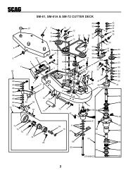
4012345382134132453978910111213141516179191824 3433313536 3265 1627640372464424344454647484950515241532545556565554241534159606162633257581612161258534158254555664246869 70 716867327412162823257226292422252410 201321357374MAG-61, MAG-72 CUTTER DECK44390S0111
MAG-61, MAG-72 CUTTER DECKRef. Part.Mag Mag Ref. PartMag MagNo. Number Description 61 72 No. Number Descripton 61 721 04020-09 Nut, Hex, 5/8-11 X X2 43278 Spacer, Cutter Blade X X3 04001-01 Bolt, Hex Head, 1/4-20 x 3/4 Gr.5 X X4 48926 Taper Hub, 1.125 Bore X X5 48924 Pulley, 5.75 Dia. X X6 48753 Pulley, 6.35 Dia. X48924 Pulley, 5.75 Dia. X7 48923 Pulley, 5.75 Double Groove X X8 04050-05 Retaining Ring, .75 Ext "E" X X9 48100-02 Bushing, Oilite - 1.125 ID X X10 48114-04 Grease Fitting X X11 46866 Arm, Idler (Includes 9 & 10) X X12 04021-09 Locknut, Elastic Stop, 3/8-16 X X13 04041-12 Flat Washer, 3/8 (.375 x 1.50 x .060) X X14 43277 Spacer, J-Hook X X15 48269 Pulley, Idler X X16 04041-07 Flatwasher, 3/8 (.391 x .938 x .105) X X17 04001-54 Bolt, Hex Head, 3/8-16 x 3 X X18 45720 Pivot, Idler Arm X X19 44107 J-Hook X X20 43077 Spacer, J-Hook X X21 04001-46 Bolt, Hex Head, 3/8-16 x 2-1/4 X X22 45037 Idler Pivot X X23 04041-08 Flatwasher, 3/4 (.776 x 1.25 x .059) X X04041-08S Flatwasher, 3/4 (.776 x 1.25 x .035) X X24 04019-03 Serr. Fl. Hex Nut, 5/16-18 X X25 48100-05 Bushing, Oilite - 3/4 ID X X26 46081 Idler Arm (Includes 10 & 25) X X27 04001-19 Bolt, Hex Head, 3/8-16 x 1 X X28 04050-02 Retaining Ring, .75 Ext "E" X X29 43028 Pull Rod, Idler X44078 Pull Rod, Idler X30 45816 Belt Cover, RH X45818 Belt Cover, RH X31 45815 Belt Cover, LH X45817 Belt Cover, LH X32 04029-03 Wingnut, Plastic, 3/8-16 X X33 481214 Gearbox, Deck Drive X X34 481213 Drive Shaft X X35 04063-01 Key, 1/4 x 1/4 x 1-1/4 X X36 04001-109 Bolt, Hex Head, 1/4-20 x 1-3/8(Full Thread) X X37 48141 Tapered Hub, 1.00 Bore X X38 48265 Belt, Cutter Deck X481295 Belt, Cutter Deck X39 48204 Belt, Cutter Deck X48089 Belt, Cutter Deck X40 46867 Cutter Deck with Decals X46868 Cutter Deck with Decals X41 46631 Spindle Assembly X X42 43298 Shaft, Cutter Spindle X X43 481024 Seal, 2.00 OD x 1.50 Bore X X44 481022 Bearing Assembly X X45 48114-04 Grease Fitting X X46 48677 Relief Fitting, Cutter Spindle X X47 43294 Spindle Housing X X48 43312 Spacer, Outside X X49 43296 Spacer, Inside X X50 481025 Seal, 2.00 OD x 1.625 OD X X51 43297 Spindle Bushing, Bottom X X52 481035 Nut, 1-1/16-18 UNEF-2B X X53 04063-08 Key, 1/4 x 1/4 x 2 X X54 481159 Blade, 21" X481160 Blade, 24-1/2" X55 04040-10 Washer, 5/8 (.688 x 1.75 x .134) X X56 04001-41 Bolt, Hex Head, 5/8-11x 9-1/2 Gr.5 X X57 48038 Roller X X58 04001-10 Bolt, Hex Head, 5/16-18 x 1-1/4 X X59 04001-08 Bolt, Hex Head, 5/16-18 x 3/4 X X60 04030-03 Lockwasher, 5/16 X X61 04040-15 Flatwasher, 5/16 (.375 x .875 x .083) X X62 45046 Shaft, Roller X X63 421820 Cover, Belt - Front X X64 04017-16 Serr. Fl Hex Head Capscrew,5/16-18 x 3/4 X X65 04030-04 Lockwasher, 3/8 X X66 04001-19 Bolt, Hex Head, 3/8-16 x 1 Gr.5 X X67 04001-09 Bolt, Hex Head, 5/16-18 x 1.0 X X68 04021-10 Hex Locknut, Elastic Stop, 5/16-18 X X69 481050 Spring, Discharge Chute X X70 46726 Discharge Chute X X71 04001-108 Bolt, Hex Head, 5/16-18 x 4-1/4 X X72 48181 Pulley, Idler X X73 04012-06 Set Screw, Hex Socket, 3/8-16 x 1/2 X X74 48098 Spindle Shield X X-NOTE-Some of the hardware is common hardware and you may purchase it locally. Be sure that all boltspurchased locally are a grade 5.41
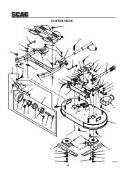
MAG-61, MAG-72 DECK SUPPORT3667697068331 265654645494344746459474862 813612360395758574749433954396766 248475150 63675244 5267233942341455 6484749357243377145424123443840462338262523363441 426123 5653555652215516317818132411211223111012262219202114731312171181275791011271229123228313029 27390S011242
MAG-61, MAG-72 CUTTER DECK SUPPORTRef. PartMag MagNo. Number Description 61 72Ref. PartMag MagNo. Number Description 61 721 45733 Cover, Belt X X2 04029-03 Wingnut, Plastic, 3/8-16 X X3 04001-52 Bolt, Hex Head, 1/2-13 x 2-1/2 X X4 481195 Actuator, Deck Lift X X5 04019-06 Serr. Fl. Hex Nut, 1/2-13 X X6 04050-05 Retaining Ring, 1.125 Ext X X7 43356 Pin, Deck support Mounting X X8 04050-08 Retaining Ring, 1.00 Ext "E" X X9 45728 Lift Bellcrank, LH Rear X X10 421878 Link, Deck Support X X11 04001-117 Bolt, Hex Head, 7/16-14 x 1-3/4 X X12 04019-05 Serr. Fl. Hex Nut, 7/16-14 X X13 04063-19 Key, 1/4 x 1/4 x 3/4 X X14 481215 Spring, Deck Lift X X15 421838 Anchor, Deck Spring X X16 04001-119 Bolt, Hex Head, 5/8-11 x 5-1/2 X X17 04017-16 Serr. Fl. Hex Head CPSCR,5/16-18 x 3/4 X X18 422027 Retainer, Spring X X19 04020-21 Hex Nut, 3/4-16 X X20 46865 Push Rod Assy (Includes 19, 21, 23,53) X X21 48100-06 Bushing, Olite - 3/4 ID X X22 04019-03 Serr. Fl. Hex Nut, 5/16-18 X X23 48114-04 Grease Fitting X X24 45727 Lift Bellcrank, Front X X25 45722 Tube, LH Caster (Shown) X45724 Tube, LH Caster (Shown) X45723 Tube, RH Caster (Not Shown) X45725 Tube, RH Caster (Not Shown) X26 48100-08 Bushing, Olite - 1.00 ID X X27 43041 Spacer X X28 48537 Wheel Assembly, Caster (includes29, 30, 31, 32) X X29 48006-07 Retainer X X30 48006-06 Bearing, Roller X X31 48537-03 Rim X X32 48537-02 Tire X X33 04012-04 Setscrew, Hex Socket, 5/16-18 x .75 X X34 43022 Sleeve, Caster Wheel X X35 04001-80 Bolt, Hex Head, 1/2-13 x 6-1/2 X X36 04021-07 Hex Locknut, Elastic Stop, 1/2-13 X X37 46869 Frame, Deck Support (Includes 23,38,39, 74) X X38 48100-02 Bushing, Olite - 1-1/8 ID X X39 48100-08 Bushing, Olite - 1.00 ID X X40 04021-13 Hex Locknut, Elastic Stop, 5/8-11 X X41 04042-05 Flatwasher, 1" (1.062 x 1.75 x .10) X X04041-14 Flatwasher, 1" (1.062 x 1.50 x .048) X X42 43353 Spacer X X43 04001-45 Bolt, Hex Head, 3/8-16 x 2 X X44 04021-09 Hex Locknut, Elastic Stop, 3/8-16 X X45 04020-09 Hex Nut, 5/8-11 X X46 43270 Swivel Joint, RH X X47 04040-09 Flatwasher, 5/8 (.656 x 1.312 x .095) X X48 04050-01 Retaining Ring, 5/8 Ext "E" X X49 45731 Lever, Deck Lift X X50 43271 Swivel Joint, LH X X51 04064-11 Pin, Clevis, 1/2 x 2.25 X X52 04044-01 Flatwasher, Nylon, 1" (.54 x 1.125x 25) X X53 481217 Rod End, Male, 3/4-16 RH X X54 04001-120 Bolt, Hex Head, 3/4-16 x 3 X X55 04021-14 Hex Locknut, Elastic Stop, 3/4-16 X X56 43352 Spacer X X57 04020-04 Hex Nut, 3/8-16 X X58 43357 Swivel Joint, LH X X59 44113 Rod, Height Indicator X X60 04004-15 Stud, Mower Lift X X61 04063-01 Key, 1/4 x 1/4 x 1-1/4 X X62 45729 Lift, Bellcrank, RH Rear X X63 04062-01 Cotter Pin, Hair - 0.94 x 1.62 X X64 481216 Actuator, Cutting Height X X65 421834 Link, Deck Travel Limit X X66 04001-118 Bolt, Hex Head, 1/2-13 x 4-3/4 X X67 04040-07 Flatwasher, 1/2 (.531 x 1.06 x .095) X X68 45730 Lever, Bellcrank Actuation X X69 04001-72 Bolt, Hex Head, 1/2-13 x 2 X X70 04020-07 Hex Nut, 1/2-13 X X71 45325 Yoke, Caster Wheel X X72 04066-01 Quick Pin X X73 45332 Shaft, Push Rod X X74 481331 Decal, Cutting Height X X75 481379 Cover, Spring X X-NOTE-Some of the hardware is common hardware and you may purchase it locally. Be sure that all boltspurchased locally are a grade 5.43
44123 4 45691010111213143536151617 18 18192021390S0113232426 252728221639413833323137344030294246434445484849505452534757414651468738553565859RIDER FRAME6061
RIDER FRAMERef. PartNo. Number Description1 46029 Handle, Steering (Includes 2)2 48159 Handle Grip3 04021-10 Hex Locknut, Elastic Stop, 5/16-184 04040-15 Flatwasher, 5/16 (.375 x .875 x .083)5 04001-12 Bolt, Hex Head, 5/16-18 x 1.756 481156 Seat (with Adjuster Rails)7 421976 Plate, Seat Mount8 04003-11 Carriage Bolt, 3/8-16 x 1-1/49 04050-05 Retaining Ring - 1.125 Ext10 48100-02 Bushing, Oilite - 1-1/8 ID11 46870 Frame, Steering12 04001-83 Bolt, Hex Head, 7/16-14 x 3-1/213 45606 Pedal, Foot Interlock14 481056 Spring, Foot Interlock Switch15 45698 Pivot, Rear Yoke16 481154 Connector Link, #50 Chain17 43329 Anchor Bolt, Chain18 04020-12 Nut, Jam, 3/8-1619 45794 Yoke, Rear20 04021-13 Hex Locknut, Elastic Stop, 5/8-1121 43020-05 Spacer, Rear Wheel22 481345 Rear Wheel Assembly (Includes 23-29)23 48005-06 Seal, Grease24 48005-05 Bearing Cone25 48005-04 Bearing Cup26 48114-06 Grease Fitting27 48005-03 Rim (Includes 23, 24, 25 & 26)28 481345-02 Tire29 43398 Sleeve, Rear Tire30 43020-06 Spacer, Rear Wheel31 04001-91 Bolt, Hex Head, 7/16-14 x 2-1/232 04001-115 Bolt, Hex Head, 5/8-11 x 11-1/433 481476 Switch, Foot InterlockRef. PartNo. Number Description34 04021-08 Hex Locknut, Elastic Stop, 1/4-2035 04017-17 Serr. Fl. Hex Head Capscrew, 5/16-18 x 1.0036 04010-17 Screw, Flat Hed, #10-32 x 3/437 45699 Footplate, LH38 04019-03 Serr. Fl. Hex Nut, 5/16-1839 481152 Chain, Steering - #5040 45696 Shaft, Steering41 48100-01 Bushing, Bronze - .877 ID42 04003-18 Carriage Bolt, 1/2-13 x 1-3/443 421784 Pad, Reinforcement44 04019-06 Serr. Fl. Hex Nut, 1/2-1345 45502 Foot Pedal46 48114-04 Grease Fitting47 46880 Footplate, RH48 48100-06 Bushing, Oilite - 3/4 ID49 45506 Foot Pedal Arm50 04065-01 Pin, Drive Lock, 3/16 x 1-1/451 04019-04 Serr. Fl. Hex Nut, 3/8-1652 42366 Reinforcement, Spring53 42026 Spring, Seat Support54 04021-11 Hex Locknut, Elastic Stop, 7/16-1455 04003-12 Carriage Bolt, 5/16-18 x 3/456 421988 Retainer, Bolt57 04050-03 Retaining Ring, 7/8 Ext58 421755 Guide, Top Chain59 421757 Divider, Chain Spacer60 481480 Armrest Assembly61 481158 Track Set, Seat-NOTE-Some of the hardware is common hardware and you may purchase it locally. Be sure that all boltspurchased are a grade 5.45
ENGINE DECK1 375317 56235241817375047515657751746667 615848584351424416171554394537142940171211491363A38 10158 968 657135B596414651627696160AB6364701462 17 186614192421204137361928252655343033323122390S01142346
ENGINE DECKRef. PartNo. Number Description1 422002 Catch, Hood Latch2 04010-01 Screw, Round Head Washer, #10-32 x 1/23 481309 Latch, Hood4 04020-01 Hex Nut, #10-325 421801 Stiffener, Hood6 * Engine, Kubota, 28 HP Diesel7 422236 Hood8 421802 Mounting Plate, Engine9 04030-05 Lockwasher, 7/1610 04002-10 Bolt, Hex Head, M10 - 1.25 x 2511 04021-11 Hex Locknut, Elastic Stop, 7/16-1412 04020-07 Hex Nut, 1/2-1313 04030-06 Lockwasher, 1/214 04019-06 Serr. Fl. Hex Nut, 1/2-1315 04017-38 Serr. Fl. Hex Head Capscrew, 1/2-13 x 1-1/216 421782 Stop, Cutter Deck17 04019-03 Serr. Fl. Hex Nut, 5/16-1818 421806 Anchor, Deck Spring19 04001-52 Bolt, Hex Head, 1/2-13 x 2-1/220 04017-16 Serr. Fl. Hex Head Capscrew, 5/16-18 x 3/421 422027 Retainer, Spring22 48680 Castle Nut, 1.0-20 UNEF23 04028-01 Nut, Wheel24 481205 Wheel Assembly (Includes 25, 26)25 481205-02 Tire, 23 x 1050 -12, 4-ply26 481205-03 Rim27 46825 Hub, Wheel (includes 28)28 04008-01 Bolt, Hub29 04040-15 Flat Washer, 5/16 (.375 x .875 x .083)30 48461 Parking Brake Assembly (Includes 31, 32,33, 34)31 48461-02 Brake Pads - Pair32 48461-03 Springs - Pair33 48461-05 Clip34 48461-04 Actuating Arm35 48769 Motor, Hydraulic - White (Includes 22)Ref. PartNo. Number Description36 04001-28 Bolt, Hex Head, 7/16-14 x 1-1/437 04003-12 Carriage Bolt, 5/16-18 x 3/438 43394 Stud, Metric39 48205 Pad, Rubber40 04021-10 Nex Locknut, Elastic Stop, 5/16-1841 421798 Battery Box42 481177 Battery43 421799 Hold Down, Battery44 04003-20 Carriage Bolt, 5/16-18 x 1045 421781 Support Bracket, Hydraulic Tank46 48711 Hydraulic Tank47 481164 Cap, Hydraulic Tank48 421288 Strap, Hydraulic Tank49 04017-05 Serr. Fl. Hex Head Capscrew, 1/4-20 x 3/450 04021-08 Hex Locknut, Elastic Stop, 1/4-2051 04003-14 Carriage Bolt, 5/16-18- 1/252 481165 Hinge53 421783 Plate, Hinge54 45862 Engine Deck55 04061-04 Pin, Cotter, 5/32 x 1-1/256 481284 Bumper, Rubber57 04019-03 Nut, 5/16-18 Serrated Flange58 481440 Adapter, Remote Oil Filter59 481441 Gasket, Oil Filter Adapter60 481442 MTG Bolt, Filter Adapter61 48603-04 O- Ring62 481443 Reducer, Remote Filter63 481444 Hose Assy., Remote Filter64 481445 Hose Assy., Remote Filter65 481446-01 Connector, 1/2 Pipe x 3/4 JIC66 481447 Nut, 7/8 - 1467 481457 Spring Filter Adapter68 48572-08 Tube Union, 7/8-14 JIC x O-Ring69 422239 Guard Oil Filter70 * Oil Filter, Engine71 04001-01 Bolt, 1/4-20 X .75 Hex Head*Available through the engine manufacturer only.-NOTE-Some of the hardware is common hardware and you may purchase it locally. Be sure that all boltspurchased are a grade 5.47
RADIATOR/OIL COOLER14292722331730685 2891124231025262324112021916181315161714122221390S011548
RADIATOR/OILCOOLERRef. PartNo. Number Description1 481207 Hose, Upper Radiator2 48136-06 Clamp, Hose3 45783 Shroud, Fan4 04019-03 Serr. Fl. Hex Nut, 5/16-185 * Tank, Coolant Overflow6 422192 Mounting Bracket, Coolant Tank7 04003-12 Carrage Bolt, 5/16-18 x .758 481286 Radiator with Oil Cooler9 45784 Frame, Debris Screen10 45785 Screen. Debris11 04001-06 Bolt, Hex Head, 1/4-20 X 5/812 422010 Side Rail, Debris Screen13 421992 Bracket, Radiator Mounting14 04003-11 Carriage Bolt, 3/8-16 x 1-1/415 * Cushion, Radiator Mounting16 * Washer, Radiator Mounting17 04021-05 Locknut, 3/8-1618 * Cushion, Radiator Mounting19 481302 Drain Cock20 481206 Hose, Lower Radiator21 04041-07 Flatwasher, 3/8 (.391 x .938 x .105)22 04021-09 Hex Locknut, Elastic Stop, 3/8-1623 04040-14 Flatwasher, 1/4 (.312 X .75 X .065)24 04030-02 Lockwasher, 1/425 48576-03 Coupling, 1/4 NPT26 481383-01 Nipple, 1/4 NPT x 2.027 422194 Strap, Coolant Bottle28 04001-44 Bolt, Hex Head, 1/4-20 x .5029 04001-59 Bolt, Hex Head, 1/4-20 x 1.2530 04019-02 Serr. Fl. Hex Nut, 1/4-2031 04021-08 Hex Locknut, Elastic Stop, 1/4-20* Available only through the engine manufacturer.-NOTE-Some of the hardware is common hardware and you may purchase it locally. Be sure that all boltspurchased are a grade 5.49
MUFFLER AND AIR CLEANER4312 15610978201119161518151415 131714121550390S0116
MUFFLER AND AIR CLEANERRef. PartNo. Number Description1 48136-08 Hose Clamp2 481191 Hose, Air Intake3 481333 Cap. Precleaner4 04100-03 U-Bolt5 481192 Air Cleaner6 421981 Mounting Bracket, Air Cleaner7 04030-03 Lockwasher, 5/168 04020-03 Nut, Hex, 5/16-189 * Gasket, Manifold10 481340 Adapter, Manifold11 04015-07 Capscrew, Socket Head, M8-1.125 x 2012 422029 Brace, Muffler Suport13 04001-09 Bolt, Hex Head, 5/16-18 x 114 04003-12 Carriage Bolt, 5/16-18 x 3/415 04019-03 Serr. Fl. Hex Nut, 5/16-1816 421983 Bracket, Muffler Support17 481439 Muffler18 48633 Clamp, Exhaust Pipe19 422254 Muffler Guard20 04011-08 Screw, 10-32 x .50 Type F HH*Available only through the engine manufacturer.-NOTE-Some of the hardware is common hardware and you may purchase it locally. Be sure that all boltspurchased are a grade 5.51
5212345678910111213814151627302646335032 50945343536372938394041 4248244324471827282819202322212351314446491725DECK DRIVE SYSTEM390S0117
DECK DRIVE SYSTEMRef. PartNo. Number Description1 04001-101 Bolt, Hex Head, 7/16-20 x 2-1/22 04030-05 Lockwasher, 7/163 481204 Clutch, Electric4 481104 Belt, Deck Drive5 46827 Spindle, Deck Drive (Includes 6 thru 16)6 43321 Shaft, Deck Drive7 481024 Seal, 2.00 O.D. 1-1/2 Bore8 481022 Roller Bearing (Replace as a set only)9 48114-04 Grease Fitting10 43294 Housing, Spindle11 48677 Relief Fitting12 43296 Spacer, Outside13 43312 Spacer, Inside14 481025 Seal, 2.00 O.D. x 1-5/8 Bore15 43297 Spindle Bushing, Bottom16 481112 Nut, 1-1/16-1817 04063-21 Key, #807 Woodruff, 1/4 x 7/818 04002-13 Bolt, Hex Head, M8-1.25 x 4019 43428 Base, Anti-Rotation-Clutch20 481469 Isolator, Rubber21 04020-03 Nut, Hex, 5/16-1822 04040-15 Flatwasher, 5/16 (.375 x .875 x .083)23 04030-03 Lockwasher, 5/1624 04019-03 Serr. Fl. Hex Nut, 5/16 - 1825 45873 Anchor Bracket, J-Bolt26 04001-46 Bolt, Hex Head, 3/8-16 x 2-1/4Ref. PartNo. Number Description27 04021-09 Hex Locknut, Elastic Stop, 3/8-1628 04041-07 Flatwasher, 3/8 (.391 x .938 x .105)29 48181 Pulley, Idler30 43028 Rod, J-Hook31 43336 Spacer32 46871 Idler Arm, Clutch33 45212 Bracket, Idler Pivot34 04017-16 Serr. Fl. Hex Head Capscrew, 5/16-18 x 3/435 43330 Hub, Brake36 04001-10 Bolt, Hex Head, 5/16-18 x 1-1/437 04017-19 Serr. Fl. Hex Head Capscrew, 5/16-18 x 1-1/238 45792 Belt Guard, Electric Clutch39 422018 Brace, Fan Support - LH40 45712 Upright, Fan Support - LH41 04017-27 Serr. Fl. Hex Head Capscrew, 3/8-16 x 142 04003-12 Carriage Bolt, 5/16-18 x 3/443 04019-06 Serr. Fl. Hex Nut, 1/2-1344 43282 Spacer, J Pull Rod45 04050-02 Retaining Ring, .75 Ext46 04019-03 Serr. Fl. Hex Nut, 5/16-1847 04003-19 Carriage Bolt, 1/2-13 x 1-1/448 04021-07 Lock Nut, Elastic Stop, 1/2-1349 04041-11 Flat Washer, 3/8 ( .406 x 1.50 x .179)50 48100-05 Bushing, Oilite - .753 I.D.51 04019-05 Nut, 7/16-14 Serr. Flg.-NOTE-Some of the hardware is common hardware and you may purchase it locally. Be sure that all boltspurchased are a grade 5.53
PUMP AND FAN DRIVE SYSTEMS1412878 71115107798161 23458174868711173474634351829494520 24PART OFENGINE222350133621254943187373839272819267832333040444221743544110390S0118
PUMP AND FAN DRIVE SYSTEMSRef. PartNo. Number DescriptionRef. PartNo. NumberDescription1 04021-16 Hex Locknut, 1/2-202 43335 Spacer, Fan3 48442 Bearing4 04003-19 Carriage Bolt, 1/2-13 x 1-1/45 46872 Bracket, Fan Mounting (Includes 3, 48)6 422017 Idler Bracket, Fan Drive7 04021-09 Hex Locknut, Elastic Stop, 3/8-168 04041-07 Flat Washer, 3/8 (.391 x .938 x .105)9 04003-06 Carriage Bolt, 1/4-20 x 110 04001-32 Bolt, Hex Head, 3/8-16 x 1-1/411 04003-11 Carriage Bolt, 3/8-16x 1-1/412 422019 Brace, Fan Support13 04019-02 Serr. Fl. Hex Nut, 1/4-2014 421808 Guard, Pump Belt15 04021-08 Hex Locknut, Elastic Stop, 1/4-2016 04003-12 Carriage Bolt, 5/16-18 x 3/417 04019-06 Serr. Fl. Hex Nut, 1/2-1318 43334 Hub, Fan19 04030-02 Lockwasher,1/420 * Pulley, Fan21 04001-21 Bolt, Hex Head, 3/8-18x 1-3/422 481315 Pulley, Belt Tensioning Idler23 * Fan24 43390 Hub, Fan25 04001-114 Bolt, Hex Head, 1/2-20 x 4.75 LH Thread26 04001-116 Bolt, Hex Head, 1/4-28 x 127 481330 Pulley, 4.25 O.D. x 1.4375 I.D.28 481114 Belt, Fan Drive29 45713 Upright, Fan Support - RH30 45307 Base, Idler Pivot - Pump31 44107 Rod, J-Hook32 43282 Spacer, J Pull Rod33 48114-04 Grease Fitting34 48761 Taper Hub, .75 Bore35 48790 Pulley, Pump, 5.94 O.D.36 04001-109 Bolt, Hex Head, 1/4-20 x 3/837 481103 Belt, Pump Drive38 481168 Taper Hub, 1-7/16 Bore39 04015-09 CPSCR, Socket Head, 1/4-20 x 1-1/440 04050-02 Retaining Ring, .75 Ext41 48181 Pulley, Idler, 5.95 O.D.42 48100-05 Bushing, Olite - .75 I.D.43 46878 Arm, Idler (Includes 33, 42)44 04019-03 Serr. Fl. Hex Nut, 5/16-1845 481329 Pulley, Double Groove46 04063-22 Key, 3/8 x 1-1/447 * Stubshaft, Crankshaft48 43139 Spacer49 04003-12 Carriage Bolt, 5/16 - 18 x .7550 04040-14 Flatwasher, 1/4* Available only from the engine manufacturer.-NOTE-Some of the hardware is common hardware and you may purchase it locally, Be sure that all boltspurchased are a grade 5.55
INSTRUMENT PANEL342121201929313012 11212012 1120 19 3292712251133928591576121113168910141629202126121125249181518172221201923390S011956
INSTRUMENT PANELRef. PageNo. Number Description1 48023 Hourmeter2 481183 Gauge, Water Temperature3 481306 Gauge, Fuel Level4 481184 Voltmeter5 46873 Instrument Panel with Decal6 42413 Bracket, Fuse Holder7 04021-01 Hex Locknut, Elastic Stop, #10-328 04010-11 Screw, Round Head, #10-32 x 1-1/29 04010-01 Screw, Round Head, #10-32 x 1/210 * Timer, Glow Plug11 04031-01 Lockwasher, External Tooth, #1012 04020-01 Hex Nut, #10-3213 481182 Indicator Light, Glow Plug, Yellow Lens14 * Keyswitch15 04003-12 Carriage Bolt, 5/16-18 x 3/416 481087 Switch, Deck Lift17 46874 Mounting Bracket, Instrument Panel (Includes 18, 23)18 48100-06 Bushing, Oilite - .75 I.D.19 04040-04 Flatwasher, 5/16 (.281 x .625 x .065)20 04030-03 Lockwasher, 5/1621 04020-03 Hex Nut, 5/16-1822 04019-03 Serr. Fl. Hex Nut, 5/16-1823 48114-04 Grease Fitting24 421788 Guide, Clutch Lever25 48788 Relay, Synchronize Start and Cutter Blade26 481311 Rubber Isolator27 422193 Brace, Instrument Panel28 04001-59 Serr. Flg. Hex Head Capscrew, 5/6-18 x 3/429 04001-08 Bolt, Hex Head, 5/16-18 x 3/430 481181 Indicator Light, Oil Pressure, Red Lens31 481316 Timer, Delay Circuit32 422004 Bracket, Support Brace33 04019-02 Serr. Fl. Hex Nut, 5/16-1834 04021-19 Hex Nut, Elastic Stop, 3/8-1635 04041-07 Flatwasher, 3/8 (.391 x .938 x .105)36 04001-32 Bolt, Hex Head, 3/8-16 x 1-1/4*Available only from the engine manufacturer.-NOTE-Some of the hardware is common hardware and you may purchase it locally. Be sure that all boltspurchased are a grade 5.57
WIRING HARNESS AND ELECTRICAL COMPONENTS12831293023456789101827261111253334243213122322215171615182120191458390S0120
Ref. PageNo. Number DescriptionWIRING HARNESS AND ELECTRICAL COMPONENTS1 481216 Actuator, Cutting Height2 481185 Wire Harness3 481182 Indicator Light, Oil Pressure4 48023 Hourmeter5 481183 Gauge, Water Temperature6 481306 Gauge, Fuel Level7 481316 Timer, Delay Circuit8 481322 Fuse, 30 Amp9 * Timer, Glow Plug10 481182 Indicator Light, Glow Plug11 48788 Relay, Synchonize Start and Clutch Kill Circuit12 * Switch, Ignition13 481087 Switch, Deck Lift and Cutting Height14 481476 Switch, Safety - Parking Brake15 481474 Switch, Foot Pedal and Cutter Brake Interlocks16 481304 Sender, Fuel (includes Gasket and Screws)17 04021-10 Hex Locknut, Elastic Stop, 5/16-1818 48030-10 Clamp19 04003-12 Carriage Bolt, 5/16-18 x 3/420 481204 Electric Clutch21 * Fuel Pump, Electric22 481195 Actuator, Deck Lift23 * Sender, Oil Pressure24 04025-02 Hex Nut, M8- 1.2525 481335 Cap, Alternator Terminal26 481190 Sender, Water Temperature27 481177 Battery28 481336 Cap, Battery Terminal - Black29 481176-02 Battery Cable, Black30 481337 Cap, Battery Terminal - Red31 481176-01 Battery Cable, Red32 04025-01 Hex Nut, M6 - 1.0033 04017-16 Serr. Fl.Hex Head Capscrew, 5/16-18 x3/434 04019-03 Serr. Fl. Hex Nut, 5/16-18* Available only from the engine manufacturer.-NOTE-Some of the hardware is common hardware and you may purchase it locally. Be sure that all boltspurchased are a grade 5.59
601234 5267981710111411131416131619202137341433212225181538243625404127242821321126271421114130316351214393925252329404040CUTTER BRAKE LINKAGE390S0121
CUTTER BRAKE LINKAGERef. PartNo. Number Description1 04041-08 Flatwasher, 3/4 (.766 x 1.250 x .060)04041-08S Flatwasher, 3/4 (.766 x 1.250 x .035)2 04050-02 Retaining Ring - .75 Ext3 45702 Lever, Clutch Engage4 04021-10 Hex Locknut, Elastic Stop, 5/16-185 481163 Spring, Clutch Lever6 04019-03 Serr. Fl. Hex Nut, 5/16-187 04017-17 Serr. Fl. Hex Head Capscrew, 5/16-18 x 18 04020-04 Nut, Hex, 3/8-169 48092 Grip, Clutch Lever10 481244 Spring, Friction Control11 04041-07 Flatwasher, 3/8 (.391 x .938 x .105)12 04001-51 Bolt, Hex Head, 3/8-16 x 3-3/413 04017-26 Serr. Fl. Hex Head Capscrew, 3/8-16 x 3/414 04021-09 Hex Locknut, Elastic Stop, 3/8-1615 48464 Ball Joint, RH Thd, 3/8-1616 04001-53 Bolt, Hex Head, 5/16-18x 2-1/217 45693 Lever, Clutch18 04017-19 Serr. Fl. Hex Head Capscrew, 5/16-18 x 1-1/219 421805 Base, Brake Assembly20 481474 Switch, Interlock21 04019-04 Serr. Fl. Hex Nut, 3/8-1622 04001-31 Bolt, Hex Head, 3/8-16 x 2-1/223 46875 Lever, Brake Engage (Includes 24, 25)24 48114-05 Grease Fitting, Short25 48100-04 Bushing, Oilite - .50 I.D.26 44109 Rod, Clutch Engage27 04062-02 Cotter Pin, Hair (.080 x1.19)28 46876 Bellcrank, Clutch Engage (Includes 24, 25)29 43212 Sleeve30 04001-20 Bolt, Hex Head, 3/8-16 x 1-1/231 481034 Spring, Brake32 04001-26 Bolt, Hex Head, 3/8-16 x 1-1/433 481170 Brake Band34 43337 Anchor, Brake35 43336 Spacer, Brake36 44110 Rod, Clutch Engage37 04017-20 Serr. Fl. Hex Head Capscrew, 5/16-18 x 1-3/438 04020-14 Hex Nut, 3/8-2439 43110 Sleeve, Control Lever40 04040-04 Flatwasher, 5/16 (.344 x .688 x .065)41 04021-10 Hex Locknut, Elastic Stop, 5/16-18-NOTE-Some of the hardware is common hardware and you may purchase it locally. Be sure that all boltspurchased are a grade 5.61
62PARKING BRAKE LINKAGE123456298111087491261314151617161814 6193520212223242512242322212020262728MAG00830687631324 333162416863435
PARKING BRAKE LINKAGERef. PartNo. Number Description1 48093 Grip, Handle2 45716 Lever, Brake3 48114-04 Grease Fitting4 04050-01 Retaining Ring, .625 Ext5 04020-05 Hex Locknut, Elastic Stop, 3/8-166 04041-07 Washer, Flat, 3/8 (.391 x .938 x .105)7 48464 Ball Joint, 3/8-24 RH Thd8 04021-09 Hex Locknut, Elastic Stop, 3/8-169 45782 Arm, Weldment10 04020-14 Hex Nut, 3/8-2411 04004-23 Rod, Parking Brake12 04003-05 Carriage Bolt, 3/8-16 x 1-1/213 481474 Switch, Interlock14 04001-19 Bolt, Hex Head, 3/8-16 x 1.0015 04017-17 Serr. Fl. Hex Head Capscrew, 5/16-18 x 1.0016 04019-04 Serr. Fl. Hex Nut, 3/8-1617 45781 Mounting Base, Parking Brake18 04001-21 Bolt, Hex head, 3/8-16 x 1-1/419 421338 Link, Cam20 04019-02 Serr. Fl. Hex Nut, 1/4-2021 04001-59 Bolt, Hex Head, 1/4-20 x 1-1/422 44108 Rod, Brake Actuator23 43032 Swivel24 0462-02 Hair Pin, Cotter, .08 x 1.1925 45705 Actuator, Brake26 04017-37 Serr. Fl Hex Head Capscrew, 1/2-13 x 1-3/427 04019-03 Serr. Fl. Hex Nut, 5/16-1828 04019-06 Serr. Fl. Hex Nut, 1/2-1329 48544 Ball Joint, 3/8-24 LH Thread30 43212 Sleeve31 44124 Rod, Interlock32 45834 Bracket, Neutral Lockout Mounting33 04001-51 Bolt, Hex Head, 3/8-16 x 3.7534 45835 Bracket, Neutral Lockout35 04003-03 Carriage Bolt-NOTE-Some of the hardware is common hardware and you may purchase it locally, Be sure that all boltspurchased are a grade 5.63
6412347568307232627349351011291812132538 1723262730361439161718192021231924222131283733283215THROTTLE LINKAGE390S0123
THROTTLE LINKAGERef. PartNo. Number Description1 04003-02 Carriage Bolt, 1/4-20 x .752 421776 Mounting Base, Throttle3 04019-02 Serr. Fl. Hex Nut, 1/4-204 04001-13 Bolt, Hex Head, 5/16-18 x 2-3/45 46877 Lever, Throttle (Includes 6, 7)6 48114-05 Grease Fitting7 48100-04 Bushing, Oilite - .50 I.D.8 44115 Rod, Throttle Control9 04002-11 Bolt, Hex Head, M10 - 1.25 x 3010 45822 Mounting Bracket, Throttle11 04021-13 Hex Locknut, Elastic Stop, 5/8-1112 04041-10 Flatwasher, 5/813 481244 Spring, Friction Control14 04004-26 Stud, 5/16-24 x 4.5015 04020-03 Hex Nut, 5/16-1816 481189 Rod End, 5/16-24 RH Thread17 04040-04 Flatwasher, 5/16 (.344 x .688 x .065)18 04001-10 Bolt, Hex Head, 5/16-18 x 1-1/419 04019-02 Serr. Fl. Hex Nut, 1/4-2020 481314 Spring, Throttle Control21 04019-03 Serr. Fl. Hex Nut, 5/16-1822 04001-39 Bolt, Hex Head, 5/16-18 x 2-1/423 04021-10 Hex Locknut, Elastic Stop, 5/16-1824 04001-59 Bolt, Hex Head, 1/4-20 x 1-1425 421997 Lever, Throttle26 04021-09 Hex Locknut, Elastic Stop, 3/8-1627 48464 Ball Joint, 3/8-24 RH Thread28 04040-04 Flatwasher, 5/1629 04001-20 Bolt, Hex Head, 3/8-16 x 1-1/230 04020-14 Hex Nut, 3/8-2431 481188 Rod End, 5/16-24 LH Thread32 481092 Knob, Shifter33 481243 Disc, Friction34 04001-51 Bolt, Hex Head, 3/8-16 x 3-3/435 04030-05 Lockwasher, 7/1636 04001-125 Bolt, Hex Head, 5/8-11 X 3-1/237 43110 Sleeve38 43212 Sleeve39 04020-13 Hex Nut,5/16-24-NOTE-Some of the hardware is common hardware and you may purchase it locally. Be sure that all boltspurchased are a grade 5.65
FORWARD/REVERSE LINKAGE1234516101324610874915221712241321111820191214390S012466
FORWARD/REVERSE LINKAGERef. PartNo. Number Description1 04021-09 Hex Locknut, Elastic Stop, 3/8-162 48544 Ball Joint, 3/8-24 LH Thread3 04041-07 Flatwasher, 3/8 (.391 x .938 x .105)4 04003-05 Carriage Bolt, 3/8-16 x 1-1/25 04004-22 Rod, Transmission Control6 45708 Bellcrank, Pump Control7 04021-08 Hex Locknut, Elastic Stop, 1/4-208 04001-59 Bolt, Hex Head, 1/4-20 x 1-1/49 04003-04 Carriage Bolt, 5/16-18 x 110 04020-14 Hex Nut, 3/8-2411 04019-03 Serr. Fl. Hex Nut, 5/16-1812 43257 Bushing, Spring Keeper13 48463 Spring, Neutral Return14 48512 Bolt, Neutral Adjustment, 3/8-24 x 6-3/415 421148 Retainer, Neutral Spring16 48464 Ball Joint, 3/8-24 RH Thread17 481102 Hydraulic Pump18 04001-71 Bolt, Hex Head, 1/2-13 x 1-1/219 04030-06 Lockwasher, 1/220 04020-07 Hex Nut, 1/2-1321 04010-11 Screw, Round Head, #10-3222 04021-01 Hex Nut, Elastic Stop, #10-3223 04040-15 Flatwasher, 5/16 (.375 x .875 x .083-NOTE-Some of the hardware is common hardware and you may purchase it locally. Be sure that all boltspurchased are a grade 5.67
FUEL TANK AND LINES278 35 62329283124271302591642610231591616171614152015161816151316111622141916162115390S012568
FUEL TANK AND LINESRef. PartNo. Number Description1 46933 Fuel Tank (Includes 2, 3, 4)2 481313 Fitting, Return Line3 481304 Sender Unit, Fuel Level (Includes Gasket and Screws)4 481312 Fitting, Hose5 04017-16 Serr. Fl. Hex Head Capscrew, 5/16-18 x 3/46 481298 Cap, Diesel Fuel7 45864 Fill Neck Wlmt.8 04020-01 Hex Nut, #10-329 48136-08 Clamp, Hose10 481296 Hose, Fuel Fill11 481307 Fuel Pre-Filter12 48030-08 Clamp, Fuel Filter13 04017-05 Serr. Fl. Hex Head Capscrew, 1/4-20 x 3/414 04019-02 Serr. Fl. Hex Nut, 1/4-2015 481178 **Hose, Fuel Line16 48136-05 Clamp Hose17 481308 Valve, Fuel Shutoff18 * Fuel Pump, Electric19 * Fuel Filter (Kubota P/N 70000-43081)20 04017-17 Serr. Fl. Hex Head Capscrew, 5/16-18 x 121 04019-03 Serr. Fl. Hex Nut, 5/16-1822 04021-08 Hex Locknut, Elastic Stop, 1/4-2023 48059-03 Fuel Hose Clamp, 3/1624 481179 **Hose Fuel Line, 3/16 x 33"25 04017-04 Serr. Fl. Hex Head Capscrew, 1/4-20 x1-1/226 422003 Strap, Fuel Tank27 04030-01 Lockwasher, #1028 481431 Elbow, 90 Deg.29 481432 Bushing, Fuel Tank30 48351-10 Hose, Fuel Vent, 1/2 x21.5"31 48502-04 Clamp, Hose .75 OD Hose* Available only from the engine manufacturer.** When ordering fuel line hose, specify the length required.-NOTE-Some of the hardware is common hardware and you may purchase it locally. Be sure that all boltspurchased locally are a grade 5.69
HYDRAULIC CIRCUITS12243305262827251629171366276691323263122414151211136171082218162119 20390S012670
HYDRAULIC CIRCUITSRef. PartNo. Number Description1 481292 Hose, Pump to Oil Cooler, 5/8 Hose Barb2 48136-04 Clamp, Hose3 481301-01 Elbow, 90°,4 481202 Hose, Oil Cooler to Reservoir, 5/8 & 3/8 Hose Barb5 48939 Elbow, 90°6 48059-01 Clamp, Hose7 48936-02 Coupling, Hose, 7/8-14 SAE x 5/8 Hose Barb8 48350-13 Elbow, 90°, 1-1/16-12 JIC x 7/8-14 O-Ring9 481203-01 Elbow, 90°, 3/4 JIC Swivel x 3/4 JIC10 481197 Hose Assembly, Left Motor11 481201 Hose Assembly, Pump Inlet12 04017-05 Serr. Fl. Hex Head Capscrew, 1/4-20 x 3/413 48482 *Hose, Hydraulic, 1/4"14 481174 Filter Head15 48758 Filter, Hydraulic16 48350-03 Elbow, 90°17 48353-02 Coupling, Hose18 04021-10 Hex Nut, Elastic Stop, 5/16-1819 04040-04 Flatwasher, 5/16 (.344 x .688 x .065)20 481196 Relief Valve, Dual Cross-Over21 04001-39 Bolt, Hex Head, 5/16-18 x 2-1/422 481199 Hose Assembly, Pump to Valve23 48571-03 Tube Cap, 1-1/16-1224 48937-02 Tee, Run, 3/4 x 3/425 48350-05 Elbow, 90°, 7/8-14 JIC x 7/8-14 O-ring26 48602 *Hose, Reservoir to Filter, 3/427 48935-01 Tee, Pushlock, 1/228 481198 Hose Assembly, Right Motor29 48937-01 Tee, Run30 48309 Bushing31 48936-01 Hose BArb to JIC Swivel* When ordering hydraulic hose, specify length required-NOTE-Some of the hardware is common hardware and you may purchase it locally. Be sure that all boltspurchased are a grade 5.71
*DELAY MODULE TIMERCONTROL PANELREDREDRED RED REDREDRED*GLOW PLUGTIMER*SYNCHO-STARTRELAYWHTGRN*PARKING BRAKESWITCHGRNFUSEHOLDERPURPORNPINKPINKBLKLT. BLUGRNORNWHTPURPFUELSENDERBLKPINKBLKRED ORNBLKORNGBLKGRN*IGNITIONSWITCH*VOLTMETERBLK*FUEL GAUGE *WATERTEMPERATURE GAUGEBLK*HOURMETERBLKBLKORNIORN WHTORNORNORNPINKREDORNIGS*GLOW PLUGLIGHTORN/WHTB AE D CREDBLKORN*CUTTINGHEIGHT SWITCHIGSBLKBLKWHTORNBLKBLKBLUB AWHTE D CREDBLKRED/WHTYEL/BLKORNBLK*LOW OILPRESSURELIGHT*CLUTCHKILL CIRCUITRELAY*DECKLIFTSWITCHBLKBLKPINK/BLKREDSTARTERSOLENOIDBLKBLKREDBLUBLKBLU*ELECTRICCLUTCHORNGRN*FOOTINTERLOCKSWITCHBLUPURPBLKWHT*SYNCHO-STARTGLOW PLUGWHTGRN*OILPRESSURESENDERBLKREDREDBLKBLKGRNORNFUELPUMPORN*CLUTCHSWITCHORNENGINEWHTREDPINK/BLKORN/WHTWATER TEMPERATURESENDERALTERNATOR*CUTTING HEIGHTACTUATORRED/WHTYEL/BLKBATTERY*DECK LIFTACTUATOR390S012772
REPLACEMENT DECALS AND INFORMATIONDANGERSPINNING BLADEKEEP CLEARCONTACT CAN INJURE148071WARNINGROTATING BLADES AND BELTSKEEP HANDS, FEET & CLOTHING CLEARKEEP ALL GUARDS IN PLACESHUT OFF ENGINE & DISENGAGE BLADECLUTCH BEFORE SERVICINGCLEAR AREA OF DEBRIS BEFORE MOWINGUSE CAUTION IN DIRECTING DISCHARGEKEEP BYSTANDERS, CHILDREN & PETS AWAYREAD INSTRUCTION MANUAL BEFORE OPERATINGDO NOT OPERATE WITHOUT DISCHARGE CHUTE, MULCHINGKIT, OR ENTIRE GRASS CATCHER INSTALLED 48104027a, 7bWARNINGINSTALL BELT COVER BEFOREOPERATING MACHINEREAD OPERATOR'S MANUAL 4810395480723HEAVY DUTYCOMMERCIAL41081234548404MANUFACTURED UNDER ONE OR MOREOF THE FOLLOWING PATENTS:4,487,006 4,991,3824,885,903 4,998,9484,920,733 4,118,6174,967,543PATENTS PENDING11 126948656Ref. PartNo. Number Description1 48071 Decal, Danger - Spinning Blades2 481040 Decal, Warning - Rotating Blades3 481326 Decal, Magnum III4 48072 Decal, Heavy Duty Commercial5 481039 Decal, Warning - Belt Cover6 48404 Decal, Metalcraft - Made In USA7A 481355 Decal, <strong>Scag</strong> Logo - 12" x 4.23 (Hood)7B 48825 Decal, <strong>Scag</strong> Logo - 8.5" x 2" (Seat Back)8 481331 Decal, Cutting Height9 48656 Decal, Patent10 481186 Decal, Instrument Panel11 48320 Decal, 6112 48327 Decal, 7273
GREASE FITTING LUBRICATION CHARTLUBRICATION NO. OFLOCATION INTERVAL LUBRICANT PLACES1. Cutter Drive Spindle 40 Hours/Weekly +Lithium MP White Grease 2125 12. Cutter Deck Spindles 40 Hours/Weekly +Lithium MP White Grease 2125 33. Caster Wheel Bearing 100 Hours/Bi-Monthly Chassis Grease 24. Caster Wheel Pivot 100 Hours/Bi-Monthly Chassis Grease 25. Electric Clutch Belt Idler Arm 100 Hours/Bi-Monthly Chassis Grease 16. Cutter Drive Shaft 100 Hours/Bi-Monthly Chassis Grease 37. Cutter Belt Idler Arms 100 Hours/Bi-Monthly Chassis Grease 28. Deck Support Pivot 100 Hours/Bi-Monthly Chassis Grease 29. Deck Push Arms 100 Hours/ Bi-Monthly Chassis Grease 210. Deck Lift Bellcranks 100 Hours/Bi-Monthly Chassis Grease 411. Pump Idler Arm 100 HoursBi-Monthly Chassis Grease 112. Rear Wheel Pivot 200 Hours/Monthly Chassis Grease 113. Rear Wheel Bearings 200 Hours/Monthly +Lithium MP White Grease 2125 114. Right Hand Foot Plate Pivot 200 Hours/Monthly Chassis Grease 115. Steering Handle 200 Hours/Monthly Chassis Grease 116. Throttle Lever 200 Hours/Monthly Chassis Grease 117. Parking Brake Lever 200 Hours/Monthly Chassis Grease 118. Blade Brake Linkage Lever 200 Hours/Monthly Chassis Grease 119. Blade Brake Linkage Bellcrank 200 Hours/Monthly Chassis Grease 120. Blade Brake Control Lever 200 Hours/Monthly Chassis Grease 1* Lubrication may be required every 8 to 40 hours, depending on climate and environment. Apply twopumps of hand gun when lubricating these locations. DO NOT over-grease; damage to seal mayoccur.+ Compatible Greases: Mobilix #2 found at Mobil Service StationRonex MP found at Exxon Service StationsSuper Lube MEP #2 & Super Stay-M #2 found at Conoco StationsLidok EP #2 found at industrial shops74
SPECIFICATIONSENGINEGeneral Type ............................................................................. Heavy Duty Industrial/Commercial DieselBrand ......................................................................................... Kubota 28 HP Super 5 Series, Electric StartModel ......................................................................................... D1105-BHorsepower ................................................................................ SAE Gross Intermittent, 28 HP @ 3000 RPMType ........................................................................................... Horizontal Shaft, Water Cooled, 4-Cycle DieselDisplacement ............................................................................. 1123 cc.Low Idle ..................................................................................... 850 - 950 RPMCylinders ................................................................................... 3Order of Firing .......................................................................... 1-2-3Direction of Rotation................................................................. Counter-clockwise (Viewed From Flywheel End)Fuel Injection Pump .................................................................. Bosch MD Type, Mini PumpInjection Pressure ...................................................................... 1,991 psiInjection Timing (Before T.D.C.) ............................................. 19°Compression Ratio .................................................................... 23:1Starting System ......................................................................... Electric Starting with Cell Starter, Glow Plug In CombustionChamberFuel ............................................................................................ Diesel Fuel No. 2 -D (ASTM D975)Oil Type ..................................................................................... API Sandard, CD Grade or BetterOil Filter .................................................................................... Full Flow Oil Filter CartridgeOil Capacity............................................................................... 4 Quarts With FilterCooling ...................................................................................... Pressurized, Sealed Cooling System, 170° F Thermostat, BladeFan, Cooling Capacity 8 QuartsBelts:Alternator .............................................................................. See Engine <strong>Manual</strong> for Part NumberFan ......................................................................................... <strong>Scag</strong> Part Number - 481114Electric Clutch ...................................................................... <strong>Scag</strong> Part Number - 481104Hydraulic Pump .................................................................... <strong>Scag</strong> Part Number - 481103ELECTRICALBattery ....................................................................................... 12 VoltCharging System ....................................................................... AlternatorCharging Output ....................................................................... 12 Volt, 30 AmpSystem Polarity .......................................................................... Negative GroundStarter ........................................................................................ 12 Volt Electric Ring Gear Type, Key and Solenoid OperatedInterlock Switches ..................................................................... Left Foot Pedal, Blade Brake, and Parking BrakeFuses .......................................................................................... Three (3) 30 AmpTRACTORDrive Motors ............................................................................. 12 Cu. In. Cast Iron High Torque MotorsSteering...................................................................................... Chain and SprocketForward and Reverse Control ................................................... Pedal Operated Linkage Connected To The Hydraulic PumpParking Brake ............................................................................ Lever Actuated Linkage to Drum Brakes on Both Drive WheelAssembliesWheels:(2) Front Caster .................................................................... 12 x 3.5(2) Drive ............................................................................... 2 x 10.5 -12, 4-ply Pneumatic Tubeless, Radius Edge(1) Rear ................................................................................ 18 x 8.50 -8 NHSFuel Tank ................................................................................... Seamless Polyethylene Tank; 8 Gallon CapacityTire Pressure:Front Caster.......................................................................... 25 PSIDrive ..................................................................................... 15 PSIRear ...................................................................................... 15 PSI76
TRACTOR (CONT'D)Seat ............................................................................................ Milsco Seat With Adjustment Lever For Forward and BackMovementTravel Speed:Forward ................................................................................ 0 - 8 MPH Infinitely VariableReverse ................................................................................. 0 - 4.3 MPH Infinitely VariableCUTTER DECKNo. of Blades ............................................................................. 3Width of Cut:Mag-61 ................................................................................. 61 in.Mag-72 ................................................................................. 72 in.Blade Size:Mag-61 ................................................................................. 1/4 thick x 21" long, milled edge, 5150 alloy steelMag-72 ................................................................................. 1/4 thick x 24-1/2" long, milled edge, 5150 alloy steelBlade Spindles ........................................................................... Cast Iron with Easy Removable Taper HubsDeck Drive................................................................................. Belt Driven Electric Clutch Connected to Drive Shaft toGearbox on DeckElectric Clutch Type ................................................................. Warner “Mag Stop” Electric ClutchBlade Brake ............................................................................... Lever Controlled Linkage to Band Type Brake. Brake HubConnected to Drive ShaftCutting Height ........................................................................... Switch on Instrument Panel Controls Electric Actuator;Cutting Heights - 1-1/2" to 5-1/2"Deck Tilt .................................................................................... Switch on Instrument Panel Controls Electric ActuatorCutter Deck Belts:Blade and Gearbox Drive (Mag-61) .................................... <strong>Scag</strong> Part Number - 48204Blade and Gearbox Drive (Mag-72) .................................... <strong>Scag</strong> Part Number - 48089Blade Drive (Mag-61) .......................................................... <strong>Scag</strong> Part Number - 48265Blade Drive (Mag-72) .......................................................... <strong>Scag</strong> Part Number - 481295Gearbox Type............................................................................. Sealed Housing, Bevel Gear and Pinion TypeDrive Shaft ................................................................................ Quick-Disconnect Shaft With Two High Speed U-JointsHYDRAULIC SYSTEMHydraulic Pump ......................................................................... Sunstrand Series 15Hydraulic Cooler ....................................................................... Part of RadiatorHydraulic Oil Filter ................................................................... 10 Micron Spin-on Element TypeHydraulic Reservoir ................................................................... High Density Polyethylene; 13 Quart CapacityWEIGHTS AND DIMENSIONSLength:Mag-61 ................................................................................. 120.0"Mag-72 ................................................................................. 120.0"Tracking Width:Mag-61 ................................................................................. 54.0"Mag-72 ................................................................................. 54.0"Overall Width:Mag-61 ................................................................................. 73.0"Mag-72 ................................................................................. 84.0"Overall Width (with Discharge Chute Up):Mag-61 ................................................................................. 62.0"Mag-72 ................................................................................. 73.0"Overall Height ........................................................................... 51.0"Operating Weight:Mag-61 ................................................................................. 1,750 lb.Mag-72 ................................................................................. 1,800 lb.77
If incorrectly used, this machine can cause severe injury. Those who use and maintain themachine should be trained in its proper use, warned of its dangers, and should read the entiremanual before attempting to set up, operate, adjust or service the machine.LIMITED WARRANTY-COMMERCIAL EQUIPMENTAny part of the <strong>Scag</strong> commercial mower manufactured by <strong>Scag</strong> <strong>Power</strong> <strong>Equipment</strong> and found, in the reasonable judgmentof <strong>Scag</strong>, to be defective in materials or workmanship, will be repaired or replaced by an Authorized <strong>Scag</strong> Service Dealerwithout charge for parts and labor. This warranty is limited to the original purchaser and is not transferable. Proof ofpurchase will be required by the dealer to substantiate any warranty claims. All warranty work must be performed by anAuthorized <strong>Scag</strong> Service Dealer.This warranty is limited to the following specified periods from the date of the original retail purchase for defects in materialsor workmanship:* Wear items including drive belts, blades, hoses and tires are warranted for 90 days.* Batteries are covered for 90 days.* Frame, deck, and structural components including oil reservoir, fittings, and oil cooler arewarranted for 1 year.* Engines and electric starters are covered by the manufacturer’s warranty period.* Drive system components are warranted for 1 year by the component manufacturer, inconjunction with <strong>Scag</strong> <strong>Power</strong> <strong>Equipment</strong>. (Excluding fittings, hoses, cooling system, oilreservoir, drive belts).* Electric clutch components are warranted for 1 year.Any <strong>Scag</strong> product used for rental purposes is covered by a 90 day warranty.!WARNING:The <strong>Scag</strong> mower, including any defective part must be returned to an Authorized <strong>Scag</strong> Service Dealer within the warrantyperiod. The expense of delivering the mower to the dealer for warranty work and the expense of returning it to the ownerafter repair will be paid for by the owner. <strong>Scag</strong>’s responsibility is limited to making the required repairs and no claim ofbreach of warranty shall be cause for cancellation or rescission of the contract of sale of any <strong>Scag</strong> mower.This warranty does not cover any mower that has been subject to misuse, neglect, negligence, or accident, or that has beenoperated in any way contrary to the operating instructions as specified in the Operator’s <strong>Manual</strong>. The warranty does notapply to any damage to the mower that is the result of improper maintenance, or to any mower or parts that have not beenassembled or installed as specified in the Operator’s <strong>Manual</strong> and Assembly <strong>Manual</strong>. The warranty does not cover any mowerthat has been altered or modified, changing performance or durability. In addition, the warranty does not extend to repairsmade necessary by normal wear, or by the use of parts or accessories which, in the reasonable judgment of <strong>Scag</strong>, are eitherincompatible with the <strong>Scag</strong> mower or adversely affect its operation, performance or durability.<strong>Scag</strong> <strong>Power</strong> <strong>Equipment</strong> reserves the right to change or improve the design of any mower without assuming any obligationto modify any mower previously manufactured.All other implied warranties are limited in duration to the one (1) year warranty period or ninety (90) days for mowers usedfor rental purpose. Accordingly, any such implied warranties including merchantability, fitness for a particular purpose,or otherwise, are disclaimed in their entirety after the expiration of the appropriate one year or ninety day warranty period.<strong>Scag</strong>’s obligation under this warranty is strictly and exclusively limited to the repair or replacement of defective parts and<strong>Scag</strong> does not assume or authorize anyone to assume for them any other obligation. Some states do not allow limitationson how long an implied warranty lasts, so the above limitation may not apply to you.<strong>Scag</strong> assumes no responsibility for incidental, consequential or other damages including, but not limited to, expense forgasoline, expense of delivering the mower to an Authorized <strong>Scag</strong> Service Dealer and expense of returning it to the owner,mechanic’s travel time, telephone or telegram charges, rental of a like product during the time warranty repairs are beingperformed, travel, loss or damage to personal property, loss of revenue, loss of use of the mower, loss of time orinconvenience. Some states do not allow the exclusion or limitation of incidental or consequential damages,so the abovelimitation or exclusion may not apply to you.This warranty gives you specific legal rights, and you may also have other rights which vary from state to state.
© 1996SCAG POWER EQUIPMENTDIVISION OF METALCRAFT OF MAYVILLE, INC.PART NO. 03034PRINTED 10/96PRINTED IN USA