Anchor-Loc® Ceramic Fiber Modules - Unifrax
Anchor-Loc® Ceramic Fiber Modules - Unifrax
Anchor-Loc® Ceramic Fiber Modules - Unifrax
- No tags were found...

Create successful ePaper yourself
Turn your PDF publications into a flip-book with our unique Google optimized e-Paper software.
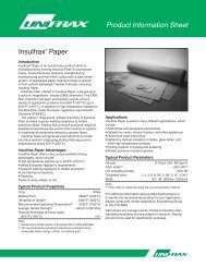
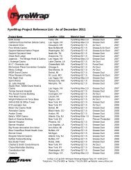
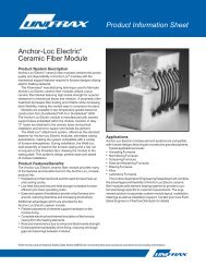
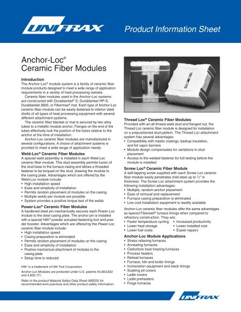
Product Information Sheet<strong>Anchor</strong>-Loc ®<strong>Ceramic</strong> <strong>Fiber</strong> <strong>Modules</strong>IntroductionThe <strong>Anchor</strong>-Loc ® module system is a family of ceramic fibermodule products designed to meet a wide range of applicationrequirements in a variety of heat processing vessels.<strong>Ceramic</strong> fiber modules used in the <strong>Anchor</strong>-Loc systemsare constructed with Durablanket ® S, Durablanket HP-S,Durablanket 2600, or <strong>Fiber</strong>max ® mat. Each type of <strong>Anchor</strong>-Locceramic fiber module can be easily fastened to interior steelshells of all types of heat processing equipment with severaldifferent attachment systems.The ceramic fiber blanket or mat is secured by two alloytubes to a metallic module anchor. Flanges on the end of thetubes effectively lock the position of the tubes relative to theanchor at the time of installation.<strong>Anchor</strong>-Loc ceramic fiber modules are manufactured inseveral configurations. A choice of attachment systems isprovided to meet a wide range of application needs:Weld-Loc ® <strong>Ceramic</strong> <strong>Fiber</strong> <strong>Modules</strong>A special weld assembly is installed in each Weld-Locceramic fiber module. This stud assembly permits fusion ofthe stud base to the furnace casing and allows a threadedfastener to be torqued on the stud, drawing the module tothe casing plate. Advantages which are offered by theWeld-Loc module include:• High installation speed• Ease and simplicity of installation• Permits random placement of modules on the casing• Multiple welds per module are possible• System provides a positive torque test of the weldsPower-Loc ® <strong>Ceramic</strong> <strong>Fiber</strong> <strong>Modules</strong>A hardened steel pin mechanically secures each Power-Locmodule to the steel casing plate. The anchor pin is installedwith a special Hilti ® powder actuated fastening tool and pow -der booster. Advantages which are offered by the Power-Locceramic fiber module include:• High installation speed• Casing preparation is eliminated• Permits random placement of modules on the casing• Ease and simplicity of installation• Positive mechanical attachment of modules to thecasing plate• Setup time is reducedHilti ® is a trademark of Hilti Tool Corporation.<strong>Anchor</strong>-Loc <strong>Modules</strong> are protected under U.S. patents #4,803,822and 4,850,171.Refer to the product Material Safety Data Sheet (MSDS) forrecommended work practices and other product safety information.Thread Loc ® <strong>Ceramic</strong> <strong>Fiber</strong> <strong>Modules</strong>Provided with an all-thread weld stud and flanged nut, theThread Loc ceramic fiber module is designed for installationon a prepositioned stud pattern. The Thread Loc attachmentsystem has several advantages:• Compatibility with mastic coatings, backup insulation,and foil vapor barriers• Module design compensates for variations in studplacement• Access to the welded fastener for full testing before themodule is installedScrew Loc ® <strong>Ceramic</strong> <strong>Fiber</strong> ModuleA self-tapping screw supplied with each Screw Loc ceramicfiber module easily penetrates mild steel up to 1 ⁄2" inthickness. The Screw Loc attachment system provides thefollowing installation advantages:• Multiple, random anchor placement• Ease of removal and replacement• Furnace casing preparation is eliminated• Low cost installation equipment is readily available<strong>Anchor</strong>-Loc ceramic fiber modules offer the same advantagesas layered <strong>Fiber</strong>wall ® furnace linings when compared torefractory construction. They are:• Faster temperature cycling • Increased productivity• Lower heat storage • Lower installed cost• Lower fuel costs• Easier repairs<strong>Anchor</strong>-Loc Module Applications• Stress relieving furnaces• Annealing furnaces• Carbottom heat treating furnaces• Process heaters• Reheat furnaces• Furnace, kiln and boiler linings• Incineration equipment and stack linings• Soaking pit covers• Ladle covers• Ladle preheaters• Forge furnaces
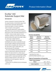
Typical Product PropertiesRecommendedModule Temperature OperatingType Grade Temperature<strong>Anchor</strong>-Loc 2200 1260°C (2300°F) 1149°C (2100°F)<strong>Anchor</strong>-Loc 2400 1316°C (2400°F) 1204°C (2200°F)<strong>Anchor</strong>-Loc 2600 1427°C (2600°F) 1343°C (2450°F)<strong>Anchor</strong>-Loc 3000 1649°C (3000°F) 1532°C (2800°F)The recommended operating temperature of <strong>Fiber</strong>frax products isdetermined by irreversible linear change criteria, not melting point.Data are average results of tests conducted under standardprocedures and are subject to variation. Results should not beused for specification purposes.Typical Product ParametersAvailable <strong>Anchor</strong>-Loc <strong>Ceramic</strong> <strong>Fiber</strong> <strong>Modules</strong>305 mm x 305 mm (12" x 12")305 mm x 152.5 mm (12" x 6")Module Construction Module Density<strong>Anchor</strong>-Loc 2200 Folded 128 kg/m 3 (8 Ib/ft 3 )Durablanket-S 160 kg/m 3 (10 Ib/ft 3 )<strong>Anchor</strong>-Loc 2400 Folded 149 kg/m 3 (9.3 Ib/ft 3 )Durablanket HP-S 192 kg/m 3 (12 Ib/ft 3 )<strong>Anchor</strong>-Loc 2600 Folded 149 kg/m 3 (9.3 Ib/ft 3 )Durablanket 2600 192 kg/m 3 (12 Ib/ft 3 )<strong>Anchor</strong>-Loc 3000 Layered 96 kg/m 3 (6 Ib/ft 3 )<strong>Fiber</strong>max mat 128 kg/m 3 (8 Ib/ft 3 )A. Weld-Loc ® Attachment SystemB. Power-Loc ® Attachment SystemForm C-1428Effective 2/09© 2009, <strong>Unifrax</strong> I LLCAll Rights ReservedPrinted in USAPage 2 of 4
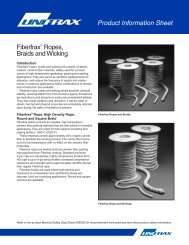
C. Thread Loc ® Attachment SystemD. Screw Loc ® <strong>Ceramic</strong> <strong>Fiber</strong> Module<strong>Anchor</strong>-Loc <strong>Modules</strong><strong>Anchor</strong>-Loc 2200 <strong>Modules</strong> – 128 kg/m 3 (8 Ibs/ft 3 )HotFace Insulation Thickness – mm (in) 102 (4) 152 (6) 203 (8) 254 (10)°C (°F) Cold Face Temperature – °C (°F) °C (°F) °C (°F) °C (°F)649 (1200) 176 (169) 162 (144) 154 (130) 50 (122)871 (1600) 112 (233) 189 (193) 177 (170) 68 (155)1093 (2000) 155 (311) 123 (254) 105 (221) 93 (199)<strong>Anchor</strong>-Loc 2200 <strong>Modules</strong> – 160 kg/m 3 (10 Ibs/ft 3 )HotFace Insulation Thickness – mm (in) 102 (4) 152 (6) 203 (8) 254 (10)°C (°F) Cold Face Temperature – °C (°F) °C (°F) °C (°F) °C (°F)649 (1200) 172 (161) 159 (138) 152 (126) 148 (118)871 (1600) 105 (221) 184 (183) 172 (162) 164 (148)1093 (2000) 144 (291) 114 (238) 197 (207) 186 (187)See note on bottom of next page.Form C-1428Effective 2/09© 2009, <strong>Unifrax</strong> I LLCAll Rights ReservedPrinted in USAPage 3 of 4
<strong>Anchor</strong>-Loc 2400 <strong>Modules</strong> – 149 kg/m 3 (9.3 Ibs/ft 3 )HotFace Insulation Thickness – mm (in) 152 (6) 203 (8) 254 (10) 305 (12)°C (°F) Cold Face Temperature – °C (°F) °C (°F) °C (°F) °C (°F)982 (1800) 101 (214) 187 (188) 177 (170) 170 (158)1093 (2000) 118 (244) 100 (212) 189 (192) 181 (177)1204 (2200) 136 (276) 115 (239) 102 (215) 192 (197)<strong>Anchor</strong>-Loc 2400 <strong>Modules</strong> – 192 kg/m 3 (12 Ibs/ft 3 )HotFace Insulation Thickness – mm (in) 152 (6) 203 (8) 254 (10) 305 (12)°C (°F) Cold Face Temperature – °C (°F) °C (°F) °C (°F) °C (°F)982 (1800) 195 (203) 181 (178) 172 (162) 166 (151)1093 (2000) 109 (229) 193 (200) 183 (181) 175 (167)1204 (2200) 125 (257) 106 (223) 194 (201) 185 (185)<strong>Anchor</strong>-Loc 2600 <strong>Modules</strong> – 149 kg/m 3 (9.3 Ibs/ft 3 )HotFace Insulation Thickness – mm (in) 152 (6) 203 (8) 254 (10) 305 (12)°C (°F) Cold Face Temperature – °C (°F) °C (°F) °C (°F) °C (°F)1149 (2100) 126 (260) 108 (226) 195 (203) 186 (187)1260 (2300) 145 (293) 123 (253) 108 (227) 197 (208)1316 (2400) 154 (310) 131 (268) 116 (240) 104 (220)<strong>Anchor</strong>-Loc 2600 <strong>Modules</strong> – 192 kg/m 3 (12 Ibs/ft 3 )HotFace Insulation Thickness – mm (in) 152 (6) 203 (8) 254 (10) 305 (12)°C (°F) Cold Face Temperature – °C (°F) °C (°F) °C (°F) °C (°F)1149 (2100) 117 (243) 199 (211) 188 (191) 180 (176)1260 (2300) 133 (271) 113 (236) 100 (212) 190 (194)1316 (2400) 141 (286) 120 (248) 106 (223) 196 (204)<strong>Anchor</strong>-Loc 3000 <strong>Modules</strong> – 96 kg/m 3 (6 Ibs/ft 3 )HotFace Insulation Thickness – mm (in) 152 (6) 203 (8) 254 (10) 305 (12)°C (°F) Cold Face Temperature – °C (°F) °C (°F) °C (°F) °C (°F)1316 (2400) 170 (338) 145 (293) 128 (262) 115 (239)1427 (2600) 189 (372) 161 (322) 142 (288) 128 (262)1538 (2800) 208 (406) 178 (352) 157 (314) 142 (287)<strong>Anchor</strong>-Loc 3000 <strong>Modules</strong> – 128 kg/m 3 (8 Ibs/ft 3 )HotFace Insulation Thickness – mm (in) 152 (6) 203 (8) 254 (10) 305 (12)°C (°F) Cold Face Temperature – °C (°F) °C (°F) °C (°F) °C (°F)1316 (2400) 155 (311) 132 (270) 117 (242) 106 (222)1427 (2600) 172 (342) 147 (296) 129 (265) 117 (242)1538 (2800) 189 (373) 162 (323) 143 (289) 129 (264)All heat flow calculations are based on a surface emissivity factor of .90, an ambient temperature of 27°C (80°F) and zero wind velocity, unlessotherwise stated.All thermal conductivity values for <strong>Fiber</strong>frax materials have been measured in accordance with ASTM Test Procedure C-177. When comparingsimilar data, it is advisable to check the validity of all thermal conductivity values and ensure the resulting heat flow calculations are based onthe same condition factors. Variations in any of these factors will result in significant differences in the calculated data.For additional information about product performance or to identify the recommended product for your application, please contact the<strong>Unifrax</strong> Application Engineering Group at 716-278-3888.Data are average results of tests conducted under standard procedures and are subject to variation. Results should not be used forspecification purposes.Form C-1428Effective 2/09© 2009, <strong>Unifrax</strong> I LLCAll Rights ReservedPrinted in USAPage 4 of 4The following are registered trademarks of <strong>Unifrax</strong>: <strong>Anchor</strong>-Loc, Durablanket, <strong>Fiber</strong>frax, <strong>Fiber</strong>max, <strong>Fiber</strong>wall, Power-Loc, Screw Loc, Thread Locand Weld-Loc.The test data shown are average results of tests conducted under standard procedures and are subject to variation. Results should not be usedfor specification purposes.Product Information Sheets are periodically updated by <strong>Unifrax</strong>. Before relying on any data or other information in this Product InformationSheet, you should confirm that it is still current and has not been superseded. A Product Information Sheet that has been superseded maycontain incorrect, obsolete and/or irrelevant data and other information.<strong>Unifrax</strong> I LLCCorporate Headquarters2351 Whirlpool StreetNiagara Falls, New York 14305-2413Telephone: 716-278-3800Telefax: 716-278-3900Internet: www.unifrax.comEmail: info@unifrax.com