ACU-T Tactical Interconnect System - Lauttamus Communications
ACU-T Tactical Interconnect System - Lauttamus Communications
ACU-T Tactical Interconnect System - Lauttamus Communications

You also want an ePaper? Increase the reach of your titles
YUMPU automatically turns print PDFs into web optimized ePapers that Google loves.
<strong>ACU</strong>-T<strong>Tactical</strong> <strong>Interconnect</strong> <strong>System</strong>Designed and Manufactured by:JPS <strong>Communications</strong>, Inc.5800 Departure DriveRaleigh, NC 27616Email: jps@jps.comJPS 5030-200200Revision 1.0June 2003
WarrantyJPS <strong>Communications</strong>, Inc. warrants its manufactured equipment to befree from defects in materials and workmanship, and to conform topublished specifications for a period of 18 months from the date ofshipment from the factory or 12 months from installation, whicheveroccurs first.JPS warrants its service work performed in connection with this warrantyto be free from defects in materials and workmanship for a period of 90days from the date the work is performed.If a defect occurs within the warranty period, the buyer shall notify JPSimmediately. JPS will repair or replace the equipment at its option, uponreturn of the equipment; shipping prepaid, to the JPS facility in Raleigh,North Carolina, USA.This warranty does not apply to damage caused by accidents, abuse orimproper installation.NO OTHER WARRANTY, EXPRESSED OR IMPLIED, INCLUDINGBUT NOT LIMITED TO THE IMPLIED WARRANTIES OFMERCHANTABILITY AND FITNESS FOR A PARTICULAR PURPOSE,SHALL APPLY.NOTICEJPS <strong>Communications</strong>, Inc. reserves the right to make changes to theequipment and specifications without prior notice.PROPRIETARY STATEMENTThe information contained in this manual is the property of JPS<strong>Communications</strong>, Inc. and is intended for the purchaser’s use only. Itmay not be reproduced without the express written consent of JPS<strong>Communications</strong>.JPS <strong>Communications</strong>, Inc.Phone: (919) 790-1011Fax: (919) 790-1456E-mail: jps@jps.com5800 Departure DriveRaleigh, NC 27616II<strong>ACU</strong>-T OPERATIONS MANUAL
Table of Contents1 GENERAL INFORMATION............................................................... 1-11.1 Scope........................................................................................ 1-11.2 Description................................................................................ 1-11.2.1 General ............................................................................ 1-11.2.2 Card Cage........................................................................ 1-11.2.3 Power Supply ................................................................... 1-21.2.4 HSP-4 Module.................................................................. 1-31.2.5 CPM-2 Module ................................................................. 1-41.2.6 DSP-1 Module.................................................................. 1-41.2.7 PSTN-1 Module................................................................ 1-41.2.8 LP-1 Module..................................................................... 1-51.2.9 <strong>System</strong> Software.............................................................. 1-51.2.10 Computer Control Software “<strong>ACU</strong> Controller” ............. 1-51.3 Optional Equipment .................................................................. 1-51.3.1 Case Option ..................................................................... 1-51.3.2 Radio Interface Cables .................................................... 1-51.3.3 AP-1 Options.................................................................... 1-61.3.4 RDI-1 Module ................................................................... 1-61.3.5 Nextel Interface................................................................ 1-71.3.6 Cell Phone Interfaces....................................................... 1-72 INSTALLATION................................................................................. 2-12.1 General ..................................................................................... 2-12.2 Unpacking and Inspection ........................................................ 2-12.3 Reshipment of Equipment ........................................................ 2-22.4 Installation Overview................................................................. 2-32.5 Installation Considerations........................................................ 2-32.5.1 Cooling ............................................................................. 2-42.6 Power Requirements ................................................................ 2-82.6.1 Battery Power for the <strong>ACU</strong>-T ........................................... 2-92.6.2 Charge Switch.................................................................. 2-92.6.3 Charger ON LED.............................................................. 2-92.6.4 Reverse Polarity Protection ........................................... 2-102.6.5 Fuse Information ............................................................ 2-102.7 Installation Checklist ............................................................... 2-112.8 External <strong>Interconnect</strong> Information........................................... 2-12<strong>ACU</strong>-T OPERATIONS MANUALIII
2.8.1 HSP-4 Module Connections ...........................................2-132.8.2 DSP-1 Module Connections ...........................................2-142.8.3 PSTN-1 Module Connections.........................................2-152.8.4 LP-1 Module Connections ..............................................2-162.8.5 AP-1 Module Connections..............................................2-172.8.5.1 AP-1 Cable Information..............................................2-182.8.6 Serial Remote Connector ...............................................2-182.9 Hardware Configuration Settings ............................................2-192.9.1 CPM-2 Switch Settings...................................................2-222.9.1.1 Baud Rate SW1-1 and SW1-2 ...................................2-222.9.1.2 Remote Control Enable SW1-3..................................2-232.9.1.3 Serial Sync Character SW1-4 ....................................2-232.9.1.4 Reserved SW1-5, 6, 7................................................2-242.9.1.5 Manufacturing Test SW1-8 ........................................2-242.9.1.6 Store Configuration SW2-1 ........................................2-242.9.1.7 SW2-2 Through SW2-8..............................................2-242.9.2 AP-1 Switch Settings ......................................................2-252.9.2.1 AP-1 General Information ..........................................2-252.9.2.2 Bypass Mode..............................................................2-252.9.2.3 AP-1 Digital Delay ......................................................2-262.9.2.3.1 AP-1 Digital Delay Setting SW3........................2-262.9.2.3.2 Digital Delay Enable AP-1 SW4-1.....................2-262.9.2.3.3 Control Signal Delay, AP-1 RX Option..............2-272.9.2.3.3.1 Control Signal Delay, AP-1 TX Option......2-272.9.2.4 AP-1 Function Enable Switches, SW4.......................2-272.9.2.5 AP-1 Control Tone Generation...................................2-282.9.2.6 AP-1 Control Tone Detection .....................................2-282.9.2.7 AP-1 Installation Notes...............................................2-292.9.3 LP-1 Jumper Settings .....................................................2-302.10 Programming Configuration Settings ......................................2-312.10.1 To Program a Module: ...............................................2-312.11 Programming Configuration Settings ......................................2-452.11.1 <strong>System</strong> Programming and Operating Items..............2-452.11.1.1 Enter Programming Mode......................................2-452.11.1.2 Console Override...................................................2-452.11.1.3 Select a Module to Program ..................................2-462.11.1.4 Exit Programming Mode ........................................2-462.11.1.5 Reset Modules to Factory Settings........................2-462.11.1.6 PIN Numbers .........................................................2-462.11.1.7 Program PIN Numbers...........................................2-472.11.1.8 Delete PIN Numbers..............................................2-472.11.1.9 Module Security Level Selection............................2-47IV<strong>ACU</strong>-T OPERATIONS MANUAL
2.11.2 HSP-4 Programming Items........................................ 2-472.11.2.1 HSP-4 Squelch Type............................................. 2-472.11.3 DSP-1 Programming Items........................................ 2-482.11.3.1 Receive Level (DSP-1).......................................... 2-482.11.3.2 Transmit Level (DSP-1)......................................... 2-492.11.3.3 COR Polarity (DSP-1) ........................................... 2-492.11.3.4 Full/Half Duplex (DSP-1) ....................................... 2-502.11.3.5 DTMF Mute Timer (DSP-1) ................................... 2-502.11.3.5.1 Transmitting DTMF via a PSTN Module........... 2-512.11.3.5.2 Transmitting DTMF via a Module other than thePSTN-1 2-512.11.3.6 COR Type, VOX/VMR Threshold, Hangtime, andAudio Delay (DSP-1) ...................................................................... 2-522.11.3.6.1 Receive (Input) Audio Delay............................. 2-552.11.3.6.2 Transmit (Output) Audio Delay......................... 2-572.11.3.7 Radio Type Selection (DSP-1) .............................. 2-582.11.3.8 COR Sampling (DSP-1) ........................................ 2-582.11.3.8.1.1 COR Sampling Programming Options: .. 2-592.11.3.8.1.2 COR Sampling On/Off ............................ 2-592.11.3.8.1.3 Initial Delay Time .................................... 2-592.11.3.8.1.4 Sampling Interval.................................... 2-602.11.3.8.1.5 Sampling Window Width......................... 2-602.11.3.9 Noise Reduction Value (DSP-1)............................ 2-602.11.3.10 Audio Muted when Squelched (DSP-1) ................ 2-612.11.3.11 Transmit Keying Tones (DSP-1) ........................... 2-612.11.3.12 COR Inhibit Time after PTT................................... 2-622.11.3.13 PTT or COR Priority (Half Duplex Only)................ 2-622.11.3.14 Module Security Level Selection ........................... 2-632.11.3.15 DTMF Commands Enable/Disable........................ 2-632.11.3.16 High Frequency Equalizer (DSP-1)....................... 2-642.11.3.17 DTMF Pre-emphasis ............................................. 2-642.11.3.18 Auxiliary Output Control ........................................ 2-652.11.3.19 Voice Prompt Initiation Delay ................................ 2-652.11.4 PSTN-1 Programming Items ..................................... 2-662.11.4.1 Telephone Line Level ............................................ 2-662.11.4.2 Telephone Receive Level Boost ........................... 2-662.11.4.3 PSTN Type............................................................ 2-662.11.4.4 Dial Mode .............................................................. 2-672.11.4.5 DTMF Mute Timer ................................................. 2-672.11.4.6 RX Audio Delay ..................................................... 2-682.11.4.7 VOX Threshold...................................................... 2-682.11.4.8 VOX Hangtime ...................................................... 2-692.11.4.9 2-Wire/4-Wire Operation (STU-III Operation)........ 2-69<strong>ACU</strong>-T OPERATIONS MANUALV
2.11.4.10 Module Security Level Selection............................2-692.11.4.11 Outgoing Ring Timer..............................................2-702.11.4.12 DTMF Command Enable .......................................2-702.11.4.13 Auxiliary Output Control.........................................2-702.11.4.14 Inactivity Disconnect Timer....................................2-712.11.4.15 Voice Prompt Initiation Delay.................................2-712.11.4.16 PSTN-1 Simplified Setup Procedure .....................2-712.11.5 LP-1 Programming Items ...........................................2-732.11.5.1 DTMF Mute Timer..................................................2-732.11.5.1.1 Transmitting DTMF via a PSTN Module ...........2-742.11.5.1.2 Transmitting DTMF via a Module other than thePSTN-1 2-742.11.5.2 RX Audio Delay......................................................2-752.11.5.3 VOX Threshold ......................................................2-752.11.5.4 VOX Hangtime .......................................................2-752.11.5.5 Module Security Level Selection............................2-752.11.5.6 Dial & Busy Tone Style ..........................................2-762.11.5.7 Ring Cadence ........................................................2-762.11.5.8 Dial Tone Enable ...................................................2-762.11.5.9 Ringback Enable....................................................2-762.11.5.10 Outgoing Ring Timer..............................................2-772.11.5.11 DTMF Command Enable .......................................2-772.11.5.12 Aux Output Control ................................................2-772.11.5.13 Voice Prompt Initiation Delay.................................2-783 OPERATION ......................................................................................3-13.1 General......................................................................................3-13.2 Front And Top Panel Controls and Indicators...........................3-13.2.1 Power ON LED (Top Panel) .............................................3-23.2.2 Charger ON LED (Top Panel) ..........................................3-23.2.3 <strong>System</strong> Connection Status Display (Top Panel) .............3-23.2.4 Speaker Switch (Top Panel).............................................3-23.2.5 Headphones Output Jack (HSP-4 Front Panel) ..............3-23.2.6 Volume Control (Top Panel).............................................3-33.2.7 Fault LEDs (HSP-4, DSP-1, PSTN-1, LP-1).....................3-33.2.8 Master/Slave LEDs (CPM-2) ............................................3-33.2.9 Mon (Monitor) LED (DSP-1, PSTN-1, LP-1).....................3-33.2.10 Signal LED (DSP-1) .....................................................3-33.2.11 PTT LED (DSP-1), VOX LED (PSTN-1, LP-1)............3-33.2.12 COR LED (DSP-1) .......................................................3-43.2.13 Ring LED (PSTN-1, LP-1) ............................................3-43.2.14 Connect LED (PSTN-1)................................................3-4VI<strong>ACU</strong>-T OPERATIONS MANUAL
3.2.15 Off-hook LED (LP-1).................................................... 3-43.3 Rear and Side Panel Connectors ............................................. 3-53.4 Basic Chassis Modules - Functions and Operation................. 3-53.4.1 CPM-2 .............................................................................. 3-53.4.2 HSP-4............................................................................... 3-63.4.2.1 Make a Connection...................................................... 3-83.4.2.2 Break a Connection ..................................................... 3-93.4.2.3 Attention Command..................................................... 3-93.4.2.4 Report Connections..................................................... 3-93.4.2.5 Disconnect Another Extension .................................... 3-93.4.2.6 Monitor Function ........................................................ 3-103.4.2.7 Store Connection Table in Memory ........................... 3-103.4.2.8 Regain Control from Console Program ..................... 3-113.4.2.9 Data / Command Modes............................................ 3-113.4.2.10 <strong>System</strong> Reset Feature........................................... 3-123.4.3 Use of Radio at HSP Connector J0 ............................... 3-123.5 Interface Modules – Functions and Operation........................ 3-143.5.1 DSP-1............................................................................. 3-153.5.2 PSTN-1 .......................................................................... 3-153.5.3 LP-1................................................................................ 3-163.5.4 AP-1 ............................................................................... 3-163.5.5 Interface Module Operational Commands ..................... 3-173.5.5.1 Make a Connection.................................................... 3-183.5.5.2 Break a Connection ................................................... 3-183.5.5.3 Attention Command................................................... 3-193.5.5.4 Monitor Function ........................................................ 3-193.5.5.5 Data / Command Modes............................................ 3-193.5.5.6 <strong>System</strong> Reset Feature............................................... 3-203.6 PIN Security............................................................................ 3-213.6.1 How PIN Security Works................................................ 3-213.6.2 PIN Security Modes ....................................................... 3-223.6.2.1 Priority Operation Mode............................................. 3-223.6.2.2 Exclusive Operation Mode......................................... 3-223.6.3 How to enable PIN Security ........................................... 3-223.6.4 How to Set <strong>ACU</strong>-T Security Levels................................ 3-233.6.5 How to Input PIN Numbers into the <strong>ACU</strong>-T Database... 3-233.6.6 How to Delete PIN Numbers from the Database ........... 3-243.6.7 How To Use The Pin Security Feature .......................... 3-243.7 <strong>ACU</strong>-T Operation .................................................................... 3-253.7.1 Unit Power-Up................................................................ 3-253.7.2 Basic Operation Scenarios ............................................ 3-26<strong>ACU</strong>-T OPERATIONS MANUALVII
3.7.2.1 Radio to Radio............................................................3-273.7.2.1.1 Conditions: ........................................................3-273.7.2.1.2 Operation Steps: ...............................................3-273.7.2.2 PSTN to Radio ...........................................................3-283.7.2.2.1 Conditions: ........................................................3-283.7.2.2.2 Operation Steps: ...............................................3-283.7.2.3 Local Operator to Radio .............................................3-293.7.2.3.1 Conditions: ........................................................3-293.7.2.3.2 Operation Steps: ...............................................3-293.7.2.4 Radio to Local Operator .............................................3-293.7.2.4.1 Conditions: ........................................................3-293.7.2.4.2 Operation Steps: ...............................................3-293.7.2.5 Radio to PSTN ...........................................................3-313.7.2.5.1 Conditions: ........................................................3-313.7.2.5.2 Operation Steps: ...............................................3-313.7.2.6 Local Phone to Radio.................................................3-323.7.2.6.1 Conditions: ........................................................3-323.7.2.6.2 Operation Steps: ...............................................3-323.7.2.7 Conference Call..........................................................3-333.7.2.7.1 Conditions: ........................................................3-333.7.2.7.2 Operation Steps: ...............................................3-333.8 SERIAL Remote Control (RS-232)............................................3-353.9 Removal and Replacement of Modules ..................................3-354 <strong>ACU</strong>-T TECHNICAL INFORMATION................................................4-14.1 Scope ........................................................................................4-14.2 General Description...................................................................4-14.3 Card Cage and Backplane ........................................................4-14.4 CPM-2 Control Processor Module ............................................4-24.5 HSP-4 Handset/Speaker Module ..............................................4-34.5.1 General Description HSP-4 ..............................................4-34.5.2 Block Diagram Description HSP-4 ...................................4-44.5.3 HSP-4 Specifications........................................................4-64.6 DSP-1 Module ...........................................................................4-84.6.1 General Description DSP-1 ..............................................4-84.6.2 Block Diagram Description DSP-1 ...................................4-84.6.3 DSP-1 Specifications......................................................4-104.7 PSTN-1 Module.......................................................................4-124.7.1 General Description PSTN-1..........................................4-124.7.2 Block Diagram Description PSTN-1 ...............................4-12VIII<strong>ACU</strong>-T OPERATIONS MANUAL
4.7.3 PSTN-1 Specifications ................................................... 4-154.8 LP-1 Module ........................................................................... 4-174.8.1 General Description LP-1............................................... 4-174.8.2 Block Diagram Description LP-1 .................................... 4-174.8.3 LP-1 Specifications ........................................................ 4-194.9 AP-1 Module ........................................................................... 4-214.9.1 AP-1 General Description .............................................. 4-214.9.2 Block Diagram Description............................................. 4-224.9.3 AP-1 Specifications........................................................ 4-235 INDEX 5-1<strong>ACU</strong>-T OPERATIONS MANUALIX
LIST OF FIGURESFIGURE 2-1 FRONT PANEL VIEW........................................................2-5FIGURE 2-2 TOP PANEL VIEW............................................................2-6FIGURE 2-3 REAR PANEL VIEW .........................................................2-7FIGURE 3-1 PICTORIAL LAYOUT FOR OPERATING SCENARIOS ...........3-26FIGURE 3-2 CONNECTION STATUS #1 ..............................................3-27FIGURE 3-3 CONNECTION STATUS #2 ..............................................3-28FIGURE 3-4 CONNECTION STATUS #3 ..............................................3-30FIGURE 3-5 CONNECTION STATUS #4 ..............................................3-32FIGURE 4-1 HSP-4 BLOCK DIAGRAM...............................................4-25FIGURE 4-2 DSP-1 BLOCK DIAGRAM...............................................4-27FIGURE 4-3 PSTN-1 BLOCK DIAGRAM ............................................4-29FIGURE 4-4 LP-1 BLOCK DIAGRAM..................................................4-31FIGURE 4-5 AP-1 BLOCK DIAGRAM .................................................4-33X<strong>ACU</strong>-T OPERATIONS MANUAL
LIST OF TABLESTABLE 1-1 GENERAL SPECIFICATIONS ................................................. 1-8TABLE 1-3 EQUIPMENT AND ACCESSORIES SUPPLIED........................... 1-9TABLE 1-5 INTERFACE MODULES ....................................................... 1-10TABLE 1-7 OPTIONAL EQUIPMENT - NOT SUPPLIED ........................... 1-11TABLE 2-1 <strong>ACU</strong>-T FUSES ................................................................. 2-10TABLE 2-3 INSTALLATION CHECKLIST................................................. 2-11TABLE 2-5CHASSIS SLOTS, EXTENSIONS, CONNECTORS, AND MODULES2-13TABLE 2-7 HSP-4 MODULE CONNECTIONS- J0.................................. 2-13TABLE 2-9 DSP-1 MODULE CONNECTIONS- J1 THROUGH J5............. 2-14TABLE 2-11 PSTN-1 MODULE CONNECTIONS- J1 THROUGH J5 ...... 2-15TABLE 2-13 LP-1 MODULE CONNECTIONS- J1 THROUGH J5 ............ 2-16TABLE 2-15 AP-1 MODULE CONNECTIONS- J1 THROUGH J5............ 2-17TABLE 2-17 SERIAL REMOTE CONNECTIONS- J10............................ 2-18TABLE 2-20 <strong>ACU</strong>-T HARDWARE CONFIGURATION SETTINGS ............ 2-20TABLE 2-22 BAUD RATE ................................................................. 2-22TABLE 2-24 REMOTE CONTROL ENABLE.......................................... 2-23TABLE 2-26 SERIAL SYNC CHARACTER ........................................... 2-23TABLE 2-28 MANUFACTURING TEST ................................................ 2-24TABLE 2-30 STORE CONFIGURATION............................................... 2-24TABLE 2-32 AP-1 DIGITAL DELAY SETTINGS, SW3.......................... 2-26TABLE 2-35 AP-1 DSP FUNCTION ENABLE, SW4 ........................... 2-28TABLE 2-36 JUMPER SETTINGS LP-1 .............................................. 2-30TABLE 2-38 <strong>ACU</strong>-T CONFIGURATION PROGRAMMING ITEMS ................... 2-34TABLE 3-1 HSP-4 OPERATIONAL COMMAND ITEMS .............................. 3-7TABLE 3-3 OPERATIONAL COMMANDS............................................... 3-17TABLE 4-1 HSP-4 SPECIFICATIONS ..................................................... 4-6TABLE 4-3 DSP-1 SPECIFICATIONS ................................................... 4-10TABLE 4-5 PSTN-1 SPECIFICATIONS................................................. 4-15TABLE 4-7 LP-1 SPECIFICATIONS ...................................................... 4-19TABLE 4-9 AP-1 SPECIFICATIONS...................................................... 4-23<strong>ACU</strong>-T OPERATIONS MANUALXI
GlossaryAP-1CORCOSCPM-2CTCSSDIPSwitchDTMFDSPDSP-1EIAExtensionHangtimeHSP-4Audio Processor Module - The AP-1 applies a varietyof functions to other <strong>ACU</strong>-T module inputs or outputs;mainly used for additional digital delay.Carrier Operated Relay - A receiver signal that gives apositive indication a carrier or signal is being receivedand the receiver is unsquelched. Same as COS.Carrier Operated Squelch - See COR.Control Processor Module - This <strong>ACU</strong> module controlsall aspects of system operation.Continuous Tone Controlled Squelch <strong>System</strong> - Asquelch system using EIA Standardized sub-audibletones in the 67Hz to 250Hz frequency range. An FMsquelch, which opens only when the proper subaudibletone is present.Dual In-Line Package Switch (“dipswitch”) - A multiunitswitch that fits into a standard DIP IC footprint.Normally contains 8 or 10 individual switches.Dual Tone Multi Frequency - The standard touch-tonetelephone dialing method sends DTMF charactersover the PSTN line.Digital Signal Processing (or Processor).Digital Signal Processor Module - The main radiointerface of the <strong>ACU</strong>-T system. DSP algorithmsprovide VOX, VMR, Audio Delay, Noise Reduction,and Tone Keying functions.Electronic Industries Association.Each interface module in the <strong>ACU</strong>-T system is givenan extension number. A user enters this extensionnumber to make a communications link via theselected module.A system with hangtime remains in the transmit modebeyond the time indicated by any keying inputs for theduration of the set hangtime For example, hangtimeadded to a VOX-based keying circuit preventstransmitter unkey during brief pauses in speech.The <strong>ACU</strong>-T Handset/Speaker/Prompt Module. Itprovides a local operator interface. <strong>System</strong> voiceprompt creation circuitry also resides on this module.XII<strong>ACU</strong>-T OPERATIONS MANUAL
GlossaryKeyLEDLMRLP-1MutePCBPortPTTRXSlotSNRSquelchTXVMRVOXPSTN-1To key a transmitter means to cause it to transmit.Light Emitting Diode.Land Mobile Radio.The Local Phone Module in the <strong>ACU</strong>-T system.To quiet or inhibit audio.Printed Circuit Board.The <strong>ACU</strong>-T side panel connectors J0 through J5provide <strong>Communications</strong> Ports to interface with othercommunications equipment.Push-to-Talk - An active PTT signal causes atransmitter to key.Receiver or Receiving.A physical location in the <strong>ACU</strong>-T chassis where amodule can be inserted.Signal-to-Noise Ratio.A means of detecting audio and causing some actionwhen it is present, such as muting an audio path.Transmit or Transmitter.Voice Modulation Recognition - A type of squelch,which is activated only by spoken words and not bytones, noise, or other audio information.Voice Operated Xmit (Transmit) - A circuit oralgorithm, which causes a transmitter to key or someother action when voice is present. This squelch typeis activated by any audio signal, and is not restrictedto voice only.The <strong>ACU</strong>-T module to interface to the Public ServiceTelephone Network<strong>ACU</strong>-T OPERATIONS MANUALXIII
Blank PageXIV<strong>ACU</strong>-T OPERATIONS MANUAL
1 General Information1.1 ScopeThis instruction manual provides the information necessary to install,configure and operate the <strong>ACU</strong>-T Intelligent <strong>Interconnect</strong> <strong>System</strong>.1.2 Description1.2.1 GeneralJPS’ <strong>ACU</strong>-T is a tactical modular interface/interconnect systempackaged in a Eurocard chassis. With this product, an intelligentinterconnect system can be configured to meet almost any interfaceapplication involving telephones and radios of any sort. The <strong>ACU</strong>-T issuitable for HF, LMR, and Inmarsat Satcom systems and offersessentially unlimited applications and expandability. A system consistsof a chassis, backplane and modules, module software, and systemcontrol software.1.2.2 Card CageThe Card Cage is a 6 1/2" wide transportable unit equipped with a frontmount Eurocard cage. Modules are plugged into an internal blackplanevia the front panel. The top of the unit is drip-proof to prevent damagefrom water entry. The module PC Boards are 100 x 220 mm. The cardcage height is 6.7” tall, 6.5” wide, with a depth of 11". The power supplyassembly is located on the unit’s rear panel and contains the main powerswitch, fuseholder, battery charger switch, and power input connectors.The <strong>ACU</strong>-T interfaces with the radios and other devices via sidemountedquick-lock circular connectors.<strong>ACU</strong>-T OPERATIONS MANUAL 1-1
1.2.3 Power SupplyThe Power Supply is a single PC board assembly mounted to the unit'srear panel. The supply accepts input voltages ranging from +9V to+16V DC and furnishes all of the internal voltages required for the <strong>ACU</strong>-T to operate. The supply also has an internal battery charger with a 1Atapered charge characteristic designed for 12V gel-cell batteries.There are two isolated power inputs. Input J7 is designed to accept+15VDC from an AC adaptor (included with the unit) and will power boththe <strong>ACU</strong>-T and the battery charger. Inputs J8 and J9 (wired in parallel;not isolated from each other) accept nominal 12V battery power.A system battery will be charged if:• The AC adapter is connected to J7 (and supplying power)• A 12V battery is connected to either J8 or J9• The battery charger switch is set to onIf the AC line voltage fails or the adapter is unplugged from J7, thebattery will automatically take over the power supply to the unit.Two battery inputs (J8 and J9) are provided so that a fresh battery maybe connected to the unit without momentarily causing the <strong>ACU</strong>-T to losepower during a battery change.The only requirement for +15VDC at J7 is to operate the battery charger.If the charger is not needed, any voltage as low as +9VDC will power theunit from J7.1-2 <strong>ACU</strong>-T OPERATIONS MANUAL
1.2.4 HSP-4 ModuleThe HSP-4 Module provides circuitry to locally monitor, configure andcontrol an <strong>ACU</strong>-T system. The user can monitor audio via the topmountedinternal speaker (or plug in an external speaker). Alternatively,the set of headphones or the handset that comes with the HSP-4 can beused. The handset includes a PTT switch to allow the user to key across-connected radio via the HSP-4. Module control and configurationis made via a 3x4 keypad (standard telephone layout) on the top panel ofthe <strong>ACU</strong>-T. For example, if the system contains a PSTN-1 module, theuser may place telephone calls manually using the HSP-4 keypad andhandset. The HSP-4 may also be used to set configuration parameters(input and output levels, for example) of all system modules.The handset and headphone jacks are mounted on the front panel of theHSP-4, and all of its other controls are mounted on the top of the <strong>ACU</strong>-T.These include: the speaker, speaker On/Off switch, volume control,keypad, and system connection status display. All system voice promptcircuitry resides on the HSP-4.The <strong>System</strong> Connection Status display is a three row by six columnmatrix of 18 LED indicators. The rows designate Connection Nets 1, 2,and 3, while the columns indicate modules that may be interconnected inthese nets: the HSP-4 and the five (max) other extension modules in thechassis. As connections are made between modules, the LEDs at theappropriate intersections light, indicating which modules are connectedtogether in what nets. When the <strong>ACU</strong>-T powers up, the status displayflashes each of the six columns left-to-right as a display test andindication of proper initialization.The HSP-4 can also act as an extra radio port for the <strong>ACU</strong>-T if its localhandset function is not required. In this case, a radio is plugged into theJ0 connector on the side of the unit. This connector interfaces with theHSP-4 and provides audio I/O as well as a VOX function plus COR andPTT signals.<strong>ACU</strong>-T OPERATIONS MANUAL 1-3
1.2.5 CPM-2 ModuleThe CPM-2 Control Processor Module controls the entire chassis via aninternal high-speed serial bus; it requests and receives status andinformation from each module and sends commands to each module. Itinstructs modules to output their audio to one of the system audio buses.The CPM-2 provides an RS-232 serial port allowing programming andmonitoring of all <strong>ACU</strong>-T functions via an external computer or seriallyinterfaced console connected to J10 on the rear panel. The front panelof the CPM-2 Module contains a Fault LED (the front panel Master andSlave LEDs are non-functional in an <strong>ACU</strong>-T).1.2.6 DSP-1 ModuleThis module is the main interface module for radios and other 4-wiredevices. It contains circuits to interface balanced or unbalanced audiofrom a receiver and to a transmitter, and has level adjustments for both.The DSP-1 contains three types of COR (receiver unsquelched conditiondetection); hardwired signal, VMR, and VOX. It offers a DSP noisereduction mode. The VMR and Noise Reduction capability make it idealfor an HF radio interface. Other features include audio delay,configurable equalization of RX input, and key tone capability.1.2.7 PSTN-1 ModuleThe PSTN Module is the 2-wire interface between the <strong>ACU</strong> system anda telephone system (as opposed to a telephone set). A telephonesystem is an entity that accepts dialing information and processes calls,such as a PSTN line, PABX line, Inmarsat Terminal, or cellular phone. (Atelephone set is a device that generates dialing information. It isinterfaced to the <strong>ACU</strong> system via the LP-1 Module.) The PSTN-1contains one 4-wire port for interfacing to 4-wire phone lines or otherdevices, and two 2-wire ports with front-panel RJ-11C jacks forinterfacing with PSTN lines or satellite equipment. The module containsring detect circuitry for automated system operation. The interface signallevels are configurable via the HSP-4 module.The module has a DSP hybrid and VOX with configurable sensitivity andhangtime. It has a DTMF receiver/generator for control and call progressrecognition. There are two uncommitted auxiliary parallel inputs and twouncommitted auxiliary parallel outputs. The two 2-wire ports arepermanently connected to front-panel RJ-11C jacks.1-4 <strong>ACU</strong>-T OPERATIONS MANUAL
1.2.8 LP-1 ModuleThe Local Phone Module is the interface to the <strong>ACU</strong> system for 2-wiredevices that generate dialing information such as a telephone set or FAXmachine. This module contains a loop current generator, ring voltagegenerator, dial and busy tone generators, a DSP hybrid with VOX and aDTMF generator/receiver. In addition to interfacing a telephone set intothe <strong>ACU</strong> system, this module can be used as a telephone "line card" in amini-PBX system.1.2.9 <strong>System</strong> SoftwareThis high level software resides on the CPM-2 Control Processor Moduleand controls all aspects of the <strong>ACU</strong>-T's inter-operation with the outsideworld. It contains the interface protocol necessary for external computercontrol of specific <strong>ACU</strong>-T <strong>System</strong>s, and determines various aspects ofthe operator's control interface with an <strong>ACU</strong>-T <strong>System</strong>, including thetiming of the system voice prompts.1.2.10 Computer Control Software “<strong>ACU</strong>Controller”The <strong>ACU</strong> Controller allows a PC User to control the <strong>ACU</strong>-T and monitorits status. The <strong>ACU</strong> Controller is also the easiest way to set or check allof the configuration parameters of the system interface modules.1.3 Optional Equipment1.3.1 Case OptionThe <strong>ACU</strong>-T case option includes a ruggedized foam-lined carrying casethat includes the <strong>ACU</strong>-T Battery Power Option. The case holds the<strong>ACU</strong>-T with spaces for its manual, AC power adapter, and accessory kit,plus room for power cables and radio interface cables.1.3.2 Radio Interface CablesJPS offers a variety of cables that interface common radios (both mobile& portable) via the <strong>ACU</strong>-T’s side-panel CPC connectors. If a cable isrequired for a radio that JPS does not currently interface, JPS maycreate an interface cable design (under certain conditions). Contact JPSfor further information.<strong>ACU</strong>-T OPERATIONS MANUAL 1-5
1.3.3 AP-1 OptionsThe AP-1 module is a general-purpose 4-wire module that can provide avariety of DSP operations. Unlike other <strong>ACU</strong>-T modules, the AP-1 doesnot communicate with the system audio and control bus structures onthe <strong>ACU</strong>-T backplane. The AP-1 is “In Series” with the audio signal thatis routed through it via the associated CPC connector. The <strong>ACU</strong>-Tchassis provides DC power and a mounting slot for the AP-1.The DSP functions of the AP-1 can operate either on the audio andcontrol signal coming into the <strong>ACU</strong>-T module that it is associated with(AP-1 RX Option Assembly), or on the audio and control signal that isexiting the associated <strong>ACU</strong>-T module (AP-1 TX Option Assembly). TheRX and TX options include the required cabling. For example, if the AP-1TX option is being used to add digital delay to the output audio from aDSP-1 module to the associated radio, The “Y” cable allows the moduleto be placed in series with the DSP-1’s TX audio.To use, simply remove the radio interface cable from the side-panelconector associated with the DSP-1 module. Install the AP-1 moduleinto an adjacent chassis slot. Now connect the “Y” cable to the unit: P1connects to the DSP-1 module, P3 connects to the AP-1 module, andthe radio interface connector that had been removed from the <strong>ACU</strong>-T isnow reconnected to P2 of the AP-1 “Y” cable.Alternatively, the AP-1’s DSP features can be used to modify signals notassociated at all with the <strong>ACU</strong>-T. In this case, the customer canmanufacture custom cabling to suit the application.See Table 2-15 for the AP-1 pinouts for connectors J1 to J5.1.3.4 RDI-1 ModuleThe RDI-1 module can be used as a basic four-wire interface module. Itsupports PTT output and COR input, but does not have Digital SignalProcessing circuitry and therefore can not perform the sophisticated DSPalgorithms that the DSP-1 module can (VMR, VOX, Digital Audio Delay,Tone Keying, etc.). The RDI-1 has one feature that the DSP-1 moduledoes not - an RS-232 interface. Consult JPS for any systems thatrequire an RS-232 interface to a connected four-wire device.1-6 <strong>ACU</strong>-T OPERATIONS MANUAL
1.3.5 Nextel InterfaceJPS has interface cables to connect to a variety of Nextel Radios.Consult JPS for details.1.3.6 Cell Phone InterfacesJPS offers some cell-phone cradles that allow commercial cell-phones tobe connected into the system via the PSTN-1 module. Consult JPS fordetails.<strong>ACU</strong>-T OPERATIONS MANUAL 1-7
Table 1-1General SpecificationsSee Section 4 for individual module specificationsRS-232 Serial Port DB-9 Female DCE connector.J10Baud Rates: 1200, 2400, 4800, and 9600.<strong>ACU</strong>-T Top Panel Power LED, Charger LED, Speaker, SpeakerSwitch, Volume Control, Keypad, and<strong>System</strong> Connection Status Display.HSP-4 Front Panel Handset Connector, 1/8” Headphone Jack,PTT LED and FAULT LED.CPM-2 Front Panel MASTER LED, SLAVE LED, and FAULTLED.DSP-1 Front Panel Monitor, COR, Signal, PTT, and Fault LEDs.PSTN-1 Front Panel L1 and L2 RJ-11 Telephone LineConnectors, Monitor, Ring, Connect, VOXand Fault LEDs.LP-1 Front Panel P1 and P2 RJ-11 Telephone Set Connectors,Monitor, Ring, Off-hook, VOX and FaultLEDsRear PanelMain Power Switch, Battery Charger Switch,Fuseholder, DC Input Connector J7, BatteryConnectors J8 and J9 and DB-9 SerialRemote Connector.DC Input Power 15VDC @ 4A max from AC Adapter pluggedinto J7.BatteryPower +9 to +15 VDC @ 1A to 4A, depending onthe number of installed interface modules.Size7” H x 7.3” W x 11.4” D (17.8x18.5x29.0 cm).Weight8 lbs (with maximum # of interface modules).Operating-20 to +60 degrees C.TemperatureStorage-40 to +85 degrees C.TemperatureHumidity Up to 95% @ 55 degrees C.ShockMIL-STD-810D, Method 516.3, Procedure VI.Vibration MIL-STD-810D, Method 514.3, Category I.1-8 <strong>ACU</strong>-T OPERATIONS MANUAL
Table 1-3Equipment and AccessoriesSuppliedQuantity ItemJPS P/N1 <strong>ACU</strong>-T Chassis5030-200000An <strong>ACU</strong>-T system consists of a chassis,HSP-4 and CPM-2 modules, up to 5Interface Modules (See Table 1-5) in anycombination.Unused slots on the chassis are coveredwith blank plates.1 HSP-4 Module 5030-2020001 CPM-2 Module 5961-2130001 <strong>ACU</strong> Controller Software 5961-2980001 Operation & Maintenance Manual 5030-2002001 Accessory Kit5030-200150Consisting of:Qty Part Number Description1 0313-037770 Line Cord1 5030-273000 Power Supply AC Line to 15VDC 4A1 2010-200350 Screwdriver1 0313-080000 RS-232 Cable1 5030-200151 Mounting Brackets, set of 22 0640-050100 Fuse, 2AG, 5A, 250V, (F1)1 0150-200000 Handset with PTT switch, Black1 0313-060000 Cord, coiled, 5 ft, black, for handset6 0362-005003 Connector, CPC, Plug6 0362-005005 Connector, Cable Shell clamp54 0362-005002 Connector Sockets, Amp CPC1 5030-200153 <strong>ACU</strong>-T Universal Battery Cable1 5030-200154 <strong>ACU</strong>-T Aux Power Cable1 5951-707000 Extender card assemblyNote: Connector components and pins allow the user tocreate <strong>ACU</strong>-T interface cables. Alternatively, cables may bepurchased from JPS. See Table 1-7.<strong>ACU</strong>-T OPERATIONS MANUAL 1-9
Table 1-5Interface ModulesAsRequiredA/RA/RItemDSP-1 ModuleMain Interface module for connectingradios and other 4-wire devices.PSTN-1 ModuleInterface module for connecting to thePSTN, SATCOM Terminal, CellularPhone or other similar 2-wire devices.LP-1 ModuleInterface module for connecting to 2-wire devices such as a local telephoneset or FAX machine.JPS P/N5961-8180005961-2150005961-2070001-10 <strong>ACU</strong>-T OPERATIONS MANUAL
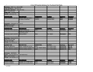
Table 1-7 Optional Equipment -Not SuppliedItem JPS P/N DescriptionSpare Parts Kit 5030-293000 Spare PartsDepot Spares 5030-291000 Depot SparesKitBattery Power 5030-205000 Battery and CablingOption KitCase Option 5030-204000 Ruggedized foam-lined caseincludes Battery Power Kit.Has storage spaces for <strong>ACU</strong>-Taccessories and some radiointerface cables.AP-1 RX OptionFor <strong>ACU</strong>-T5961-284001 “Y” cable to place the AP-1module in series with input (RX)AP-1 TX OptionFor <strong>ACU</strong>-Taudio.5961-284002 “Y” cable to place the AP-1module in series with output(TX) audio.RDI-1 Module 5961-212000 Interface module for connectingradios and other 4-wire devices.This module does not haveDSP circuitry, but does haveRS-232 capability.Radio InterfaceCablesNextel InterfaceCablesCell PhoneInterface CablesVariousVariousVariousInterface the <strong>ACU</strong>-T to commonmodels of mobile or portableradios. Consult JPS for details.Interface the <strong>ACU</strong>-T to somemodels of Nextel radios.Consult JPS for details.JPS offers several after-marketcell phone interfaces that allowsome cell phone models to beconnected into the <strong>ACU</strong>-Tsystem via the PSTN-1 Module.Consult JPS for details.<strong>ACU</strong>-T OPERATIONS MANUAL 1-11
End of Section One.1-12 <strong>ACU</strong>-T OPERATIONS MANUAL
2 Installation2.1 GeneralThis Section provides the instructions for unpacking, inspection,installation and set-up. Included are directions for reshipment ofdamaged parts or equipment.2.2 Unpacking and InspectionAfter unpacking the unit, retain the carton and packing materials until thecontents have been inspected and checked against the packing list. Ifthere is a shortage or any evidence of damage, do not attempt to use theequipment. Contact the carrier and file a shipment damage claim. A fullreport of the damage should be reported to the JPS Customer ServiceDepartment. The following information should be included in the report:1. Order Number2. Equipment Model and Serial Numbers3. Shipping Agency4. Date(s) of ShipmentThe JPS Customer Service Department can be reached by phone at(919) 790-1011, by fax at (919) 790-1456. Upon receipt of thisinformation, JPS will arrange for repair or replacement of the equipment.<strong>ACU</strong>-T OPERATIONS MANUAL 2-1
2.3 Reshipment of EquipmentIf it is necessary to return the equipment to the manufacturer, a ReturnedMaterial Authorization (RMA) number must first be obtained from JPS.This number must be noted on the outside of the packing carton and onall accompanying documents. When packing the unit for reshipment, It isbest to use the original packaging for the unit; if this is not possible,special attention should be given to providing adequate packing materialaround connectors and other protrusions, such as front panel controls.Rigid cardboard should be placed at the corners of the unit to protectagainst corner damage during shipment.Shipment should be made prepaid consigned to:JPS <strong>Communications</strong>, Inc.Customer Service Department5800 Departure DriveRaleigh, North Carolina 27616USAPlainly, mark with indelible ink all mailing documents as follows:U.S. GOODS RETURNED FOR REPAIRMark all sides of the package:FRAGILE - ELECTRONIC EQUIPMENTInspect the package prior to shipment to be sure it is properlymarked and securely wrapped.2-2 <strong>ACU</strong>-T OPERATIONS MANUAL
2.4 Installation OverviewThese steps are needed to properly prepare the <strong>ACU</strong>-T for use:1. Provide the proper power for the unit. See Section 2.6.2. <strong>Interconnect</strong> the unit with the communications system via theunit's side panel connectors. See Sections 2.7 and Figure 2-2.3. Check all internal set-ups and adjustments per the sectionsbeginning with 1.1.2.5 Installation ConsiderationsThe <strong>ACU</strong>-T is a transportable unit that may be carried by its handle tooperations in the field. The metal housing provides moderate protectionfrom the weather and assurance of operation in ambient temperaturesbetween -20 and +60 degrees C. The top of the unit is drip proof yetshould be protected from exposure to salt spray due to risk of corrosion.The unit may be permanently attached to a hard surface using themounting brackets provided in the accessory kit. Figure 2-2 and Figure2-3 provide overall unit dimensions.NOTE: When the <strong>ACU</strong>-T is installed in a high RFenvironment such as repeater site, it is recommended thatcable assemblies to each module be individually shielded.The cable shields should be connected to Pin 1 (ground) inthe CPC connectors of the <strong>ACU</strong>-T.<strong>ACU</strong>-T OPERATIONS MANUAL 2-3
2.5.1 CoolingThe <strong>ACU</strong>-T depends on radiation from its metal surfaces and naturalconvection for its cooling, therefore it must be arranged in a way thatallows for sufficient air circulation or unacceptably high internaltemperatures may result. A fully loaded <strong>ACU</strong>-T with five modulesinstalled dissipates approximately 22 watts. The unit has no internalblower or fan.A pair of installation guidelines:1) The <strong>ACU</strong>-T may be installed in an enclosed space such as atransportable case and operated continuously at temperatures thathumans are comfortable in. The transportable case supplied by JPShas the <strong>ACU</strong>-T front panel area deliberately uncovered to allow it toradiate heat from that surface.2) If the <strong>ACU</strong>-T will be operated in a high temperature area such as thetrunk of a car or other enclosed space, it must be mounted in theopen so that it can radiate heat from its metal surfaces. That is, itshould not be operated for long periods while in a high temperaturearea while also enclosed in a transportable case.2-4 <strong>ACU</strong>-T OPERATIONS MANUAL
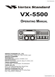
<strong>ACU</strong>-TTACTICAL INTERCONNECTHSP-4EXT 00CPM-20102INTERFACE MODULES030405HSP-4CPM-2DSP-1DSP-1DSP-1LP-1PSTN-1HANDSETMONMONMONMONMONRINGRINGPHONESP1L1P2L2MASTERCORCORCORSLAVESIGNALSIGNALSIGNALOFF HOOKCONNECTPTTPTTPTTPTTVOXVOXFAULTFAULTFAULTFAULTFAULTFAULTFAULTHSP-4 CPM-2 01 02 03 04 05Figure 2-1Front Panel View<strong>ACU</strong>-T OPERATIONS MANUAL 2-5
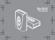
<strong>ACU</strong>-TTACTICAL INTERCONNECTPOWERONEXT 05J5CHARGERONEXT 04J4SPEAKERONEXT 03J310.85011.370EXT 02J2MINVOLUMEEXT 01J1HSPJ01 2 34 5 67 8 90 #*NET123HSP00EXTENSION01 02 03 04SYSTEM CONNECTION STATUS05Figure 2-2Top Panel View2-6 <strong>ACU</strong>-T OPERATIONS MANUAL
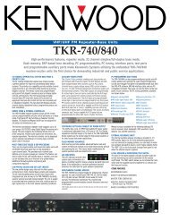
NOTE: HANDLE FOLDS DOWN0IJ8J99.000MAINPOWERF15ATYPE 2AGJ7POWER15 VDC- +- +- +BATTERYBATTERY INPUTS J8 & J9 ACCEPT 9-16 VDC @ 1-4 AMPS.THESE INPUTS ARE IN PARALLEL AND ARE NOT ISOLATED FROM EACH OTHER.ONBATTERYCHARGEROFFJ10RS-2327.3006.700J7 IS 12-16 VDC INPUT @ 1-4 AMPS, AND IS ISOLATED FROM J8 & J9.J7 CAN BE USED WITH 12 VOLT CIGARETTE LIGHTER PLUG TOCHARGE BATTERIES AT J8 AND/OR J9, BUT ONLY WITH VEHICLE ENGINE RUNNING.1739CPCCONNECTORPIN #J01GND2 SPKR OUT3GND4 ANALOG GND5MIC IN6PTT OUT7COR IN8LINE OUT9MIC LOWSIGNALJI-J5GNDAUX OUTTx BANALOG GNDRx APTT OUTCOR INTx ARx B6.5207.025Figure 2-3Rear Panel View<strong>ACU</strong>-T OPERATIONS MANUAL 2-7
2.6 Power RequirementsThe <strong>ACU</strong>-T will operate with DC supply voltage from +9 to +16 VDC.There are two isolated power inputs. Input J7 is designed to accept+15VDC from an AC adaptor (included with the unit) to power both the<strong>ACU</strong>-T and the battery charger. Inputs J8 and J9 (wired in parallel; notisolated from each other) accept nominal 12V battery power. With theincluded AC adapter connected to J7 and a 12V battery connected toeither J8 or J9, the battery will be charged (if the battery charger switchis on) as long as the AC adapter is supplying power. If the AC linevoltage fails or the adapter is unplugged from J7, the battery willautomatically take over the power supply to the unit.Two battery inputs (J8 and J9) are provided so that a fresh battery maybe connected to the unit without causing the <strong>ACU</strong>-T to lose power duringa battery change.The only requirement for having a voltage of +15VDC at J7 is to operatethe battery charger. If the charger is not needed, any voltage as low as+9VDC will power the unit from J7.Actual power consumption depends on the number of interface modulesinstalled. The DC power input characteristic of the unit is essentiallyconstant power, i.e., the input power requirement is constant so the inputcurrent varies with the input voltage and number of modules installed. Afully loaded chassis consumes 1.8A (21.6W) when run at a nominal12VDC.CAUTION: Always disconnect input power cabling fromthe <strong>ACU</strong>-T prior to servicing the unit.NOTE: Any DC power supply connected to the <strong>ACU</strong>-TDC input must be Safety Extra Low Voltage (SELV)certified.2-8 <strong>ACU</strong>-T OPERATIONS MANUAL
2.6.1 Battery Power for the <strong>ACU</strong>-TA 12V gel-cell battery connected to J8 or J9 can power the <strong>ACU</strong>-T. An18AH battery is recommended. When both battery and an AC adapterare connected, the battery will be charged and the unit will be poweredfrom adapter power as long as the AC adapter remains powered orconnected to the unit. If the adapter is unpowered or disconnected, theunit will automatically switch over to battery power. When powered by a+12V battery at J8 or J9, the <strong>ACU</strong>-T current consumption isapproximately the following: 0.3A + (0.3A * # interface modules). Inother words, the basic chassis with CPM and HSP modules draws 0.3Amps, and each interface module draws an additional 0.3 Amp. So thecurrent consumption would be the following:• Chassis with 1 module = 0.6A• Chassis with 2 modules = 0.9A• Chassis with 5 modules = 1.8A (fully loaded <strong>ACU</strong>-T)The recommended 18AH battery will give about 10 hours of operationwith a fully-loaded <strong>ACU</strong>-T, and correspondingly longer operating timewhen fewer than five modules are installed.2.6.2 Charge SwitchThe rear panel Battery Charger Switch must be set to ON to chargebatteries connected to J8 or J9. The switch should be set to OFF if anysource of power except a battery is connected to either J8 or J9.2.6.3 Charger ON LEDThis LED on the top panel will be lit when the battery charger is turnedON and a battery is connected and charging. The LED is brightest whena battery is low on charge and dims as the battery nears full charge. Ifthere is no battery connected, or the battery is fully charged, the indicatorwill not light even if the Charger switch is set to ON.<strong>ACU</strong>-T OPERATIONS MANUAL 2-9
2.6.4 Reverse Polarity ProtectionPower input J7 is protected from reverse polarity by a series diode. Ifreverse polarity power is applied at J7, the unit will not operate and nodamage will occur.Inputs J8 and J9 are reverse polarity protected by diodes to ground atthese inputs and series fuses in the cables. Note that cables attached tothese inputs MUST have a series fuse. If reverse polarity power isapplied at either J8 or J9, the internal diode will conduct and blow theseries cable fuse. The unit will not operate and no damage will occurexcept for a blown fuse.2.6.5 Fuse InformationThis section identifies the fuses used in and with the <strong>ACU</strong>-T.F1 fuses the total DC power to the unit. It protects the unit from fire orcomponent damage in the even of an internal short circuit in the <strong>ACU</strong>-Tor any of the installed modules.The Universal battery cable and Aux Power cable both have built-infuses. These fuses protect against applied reverse polarity power aswell as internal faults in the unit.Table 2-1F1 5A, 250V,2AG<strong>ACU</strong>-T FusesMainFuses all power to the<strong>ACU</strong>-T.--- 10A,250V,AGC--- 10A,250V,AGCBatteryCableAuxPowerCableReverse polarityprotection for J8, J9.Reverse polarityprotection for J8, J9.2-10 <strong>ACU</strong>-T OPERATIONS MANUAL
2.7 Installation ChecklistTable 2-3Installation ChecklistProvide suitable Mounting and See Section 2.5.Cooling.Battery Power needed? See Section 2.6.1 and 2.6.2.Make <strong>Interconnect</strong>ions.See Section 2.8 for External<strong>Interconnect</strong> Information.Serial Remote Control needed? Set Serial Remote controlON with CPM SW1-3. SetBaud Rate with CPM SW1-1and 2.Set Audio Input Levels if necessary. See Programming Items forthe DSP-1 in Table 2-38.Set Audio Output Levels if necessary. See Programming Items forthe DSP-1 in Table 2-38.Set COR Type and Polarity.See Programming Items forthe DSP-1 in Table 2-38.Set Squelch Type if necessary See Programming Items forthe DSP-1 in Table 2-38Set Telephone Line Level if necessary. See Programming Items forthe PSTN-1 in Table 2-38.Is COR Sampling needed?See Programming Items forthe DSP-1 in Table 2-38.Is Noise Reduction Needed?See Programming Items forthe DSP-1 in Table 2-38.Numerous other configuration options available but not included in thischecklist. See the manual sections beginning with 2.9.<strong>ACU</strong>-T OPERATIONS MANUAL 2-11
2.8 External <strong>Interconnect</strong> InformationThis section details the type and pin-out information for the <strong>ACU</strong>-Texternal connectors. The left-most slot in the chassis is reserved for theHSP-4 Handset/Speaker/Prompt Module and the second slot is for theCPM-2 Control Processor Module. Both of these modules are requiredfor system operation. The 5 remaining slots may be occupied by anycomplement of the various <strong>ACU</strong>-T interface modules.Each of the interface module slots (and the HSP-4 slot) has anassociated CPC connector on the side panel. The pin connectionspresented at the side panel CPC connectors depend on the type ofinterface module installed in the associated slot. The connectors for the5 interface module slots are labeled J1-J5 on the side panel. J1 isassociated with the module plugged into the slot adjacent to the CPM-2Module, and the J5 is the connector for the module plugged into theright-most slot. J0 provides external connections to the HSP-4 module.To reference the modules and system users, the 5 slots that theinterface modules plug into are associated with “extensions”. Extensions01 through 05 correspond with side panel circular connectors J1 throughJ5. The HSP module is identified by the extension “J0” (think of this assimilar to “O” for “Operator”).<strong>System</strong> users employ these extension numbers to identify theconnections they want to create. If a VHF radio were connected to theDSP module at J2 (extension 02) and the VHF operator wanted to makea call via the phone line connected to PSTN module in slot 5, he woulduse his DTMF keypad to call extension 05. If the VHF user wantedinstead to communicate directly to the local operator at the <strong>ACU</strong>-T, hewould use his DTMF keypad to connect to extension 00. A radio (orother 4-wire device) may also be connected to J0 using the sameinterface cable as would be used to connect it to J1 throuh J5. If this isdone, a connection to extension 00 will interconnect this radio. SeeSection 3.4.3 for more information regarding the use of J0 to connectradios.See Section 3 for full operational instructions.2-12 <strong>ACU</strong>-T OPERATIONS MANUAL
Table 2-5 Chassis Slots, Extensions,Connectors, and ModulesChassis Slot Extension Side CPCConnectorModule TypeHSP 00 J0 HSP-4CPM None None CPM-21 01 J1 Various2 02 J2 Various3 03 J3 Various4 04 J4 Various5 05 J5 Various2.8.1 HSP-4 Module ConnectionsThe HSP-4 module in the system must be plugged into extension 00 inthe card cage, which connects it to J0 on the side panel.Table 2-7HSP-4 Module Connections- J0PIN Signal Description1 Gnd Ground connection.2 Sprk Out External speaker connection.3 Gnd Ground connection.4 Analog Used for an audio signal return.Ground5 Mic In Microphone Input; suitable for radios also;has AGC.6 /PTT OUT Active Low output to key a radio.7 /COR In COR input from a receiver, active low.8 Line Out 0 dBm line level audio output.9 Mic Low Microphone return. Use as ground return forPin 5.<strong>ACU</strong>-T OPERATIONS MANUAL 2-13
2.8.2 DSP-1 Module ConnectionsA DSP-1 module may be plugged into any of the extensions 01 through05 in an <strong>ACU</strong>-T chassis. Its interface with the outsideworld would beavailable at the associated side panel connector, J1 through J5.Table 2-9DSP-1 Module Connections-J1 through J5PIN Signal Description1 Ground Ground connection.2 /AUX Out 1 Auxiliary Output 1- Active low; used forspecial functions only.3 TX Out B Balanced transmit audio output.4 Analog Ground Used for an audio signal return.5 RX in A Balanced receive audio input.6 /PTT Out Active Low output to key a radio.7 COR In COR input from a receiver.8 TX Out A Balanced transmit audio output.9 RX in B Balanced receive audio input.Note: For unbalanced audio, ground “B” pin of audio pair; connectunbalanced audio to “A” pin.2-14 <strong>ACU</strong>-T OPERATIONS MANUAL
2.8.3 PSTN-1 Module ConnectionsA PSTN-1 module may be plugged into extensions 01 through 05 in an<strong>ACU</strong>-T chassis.Table 2-11 PSTN-1 Module Connections-J1 through J5PIN Signal Description1 Ground Ground connection.2 /AUX In 2 Auxiliary Input 2- Active low; used for specialfunctions only.3 Tel Line 1 Tip Telephone Line 1 Tip Connection; use JP2 toenable.4 Analog Ground Used for an audio signal return.5 Tel Line 2 Ring Telephone Line 2 Ring Connection; use JP3to enable.6 /AUX Out 1 Auxiliary Output 1- Active low; used forspecial functions only.7 4WOUT 4-Wire Audio Output.8 Tel Line 1 Ring Telephone Line 1 Ring Connection; use JP1to enable.9 Tel Line 2 Tip Telephone Line 2 Tip Connection; use JP4 toenable.<strong>ACU</strong>-T OPERATIONS MANUAL 2-15
2.8.4 LP-1 Module ConnectionsAn LP-1 module may be plugged into any of the extensions 01 through05 in an <strong>ACU</strong>-T chassis.Table 2-13 LP-1 Module Connections- J1through J5PIN Signal Description1 Ground Ground connection.2 /AUX In 2 Auxiliary Input 2- Active low; used forspecial functions only.3 Tel Line 1 Tip Telephone Line 1 Tip Connection.4 Analog Ground Used for an audio signal return.5 Tel Line 2 Ring Telephone Line 2 Ring Connection.6 /AUX Out 1 Auxiliary Output 1- Active low; used forspecial functions only.7 /PTT In Active- Low PTT Input.8 Tel Line 1 Ring Telephone Line 1 Ring Connection.9 Tel Line 2 Tip Telephone Line 2 Tip Connection.2-16 <strong>ACU</strong>-T OPERATIONS MANUAL
2.8.5 AP-1 Module ConnectionsAn AP-1 module may be plugged into any of the extensions 01 through05 in an <strong>ACU</strong>-T chassis.Table 2-15 AP-1 Module Connections- J1through J5PIN Signal Description1 Ground Ground connection.2 /AUX Out 1 Auxiliary Output 1- Active low; used for specialfunctions only.3 TX Out B Balanced transmit audio output.4 Analog Used for an audio signal return.Ground5 RX in A Balanced receive audio input.6 /PTT Out Active Low output to key a radio.7 COR In COR input from a receiver.8 TX Out A Balanced transmit audio output.9 RX in B Balanced receive audio input.Note: For unbalanced TX output audio, ground “B” pin of audio pair;connect unbalanced audio to “A” pin.<strong>ACU</strong>-T OPERATIONS MANUAL 2-17
2.8.5.1 AP-1 Cable InformationThe AP-1 module applies DSP functions to its throughput audio and/orcontrol lines. This audio can be applied to either the input or the outputof other <strong>ACU</strong>-T interface modules. The AP-1 Option cabling determineswhether its functions are applied to the associated <strong>ACU</strong>-T module’s inputor to its output. The cable provided with the AP-1 module is designed tobe used in series with the standard radio interface cable.For example, if extra audio delay must be added to a trunked radiointerfaced with a DSP-1 module in the <strong>ACU</strong>-T chassis, the AP-1 TXOption must be used.To install, disconnect the trunked radio’s interface connector from theside panel of the <strong>ACU</strong>-T. Install the AP-1 module (configured for theproper audio delay) into a chassis slot adjacent to the DSP-1 module.Attach the AP-1 TX Option cable as follows:• P1 connects to the DSP-1’s side panel connector• P3 connects to the AP-1’s side panel connector• P2 connects to the interface cable from the trunked radio; P2 isthe same configuration as the <strong>ACU</strong>-T’s side panel connector sothat it mates with any standard <strong>ACU</strong>-T interface cable.2.8.6 Serial Remote ConnectorThis female 9-pin DB-9 connector provides a serial RS-232 interface withthe CPM-2 module. The connector is labeled J10 on the rear panel.Standard DCE pinout is used.Table 2-17 Serial Remote Connections- J10PINSignal2 TX Data3 RX Data5 Ground2-18 <strong>ACU</strong>-T OPERATIONS MANUAL
2.9 Hardware Configuration SettingsIn the <strong>ACU</strong>-T, there are two types of system and module configurationsettings: Hardware and Programming. Changing physical pots, jumpers,and switches on each module adjusts hardware settings. Programmingitems for each module are set via the HSP-4 Keypad or by RS-232remote control. In general, the hardware settings are done once atinstallation and need not be changed, while the programming items aremore likely to be changed after installation to optimize systemperformance. This section explains all hardware configuration switchand jumper settings for each of the modules in a system. A fullexplanation of Programming Configuration Settings follows.To access the potentiometers, jumpers and switches listed in Table 2-20,use the Extender Card found in the Accessory Kit. Remove the moduleneeding adjustment and install the extender card in its place. Insert theExtender Card with its connector on the right side of the card (theExtender Card connector must be on the same side of the extender cardas the module components). All modules can be safely "hot-plugged"(removed and re-inserted with the unit's power on) without damage, butinterruptions to unit operation may occur.<strong>ACU</strong>-T OPERATIONS MANUAL 2-19
Table 2-20 <strong>ACU</strong>-T Hardware ConfigurationSettingsRear Panel Designator Factory SettingCharger On/Off -- OffHSP-4 Module Configuration Designator Factory SettingInternal/External SpeakerSelectionJP-1Internal SpeakerEnabledCPM-2 Module Configuration Designator Factory SettingSerial Port Baud Rate SW1-1, 2 9600RS-232 Serial Remote Control SW1-3 EnabledEnable/DisableSerial Sync CharacterSW1-4 Not requiredRequirementReserved for future use SW1-5 OffChassis Configuration SW1-6, 7 Single Chassis(multi-chassissystems are notpossible with the<strong>ACU</strong>-T)Manufacturing TestSW1-8 DisabledEnable/DisableStore ConfigurationsSW2-1 EnabledEnable/DisableReserved for future useSW2- Off2,3,4,5,6,7,8Reserved for future use All of SW-3 OffDSP-1 Module Configuration Designator Factory SettingHi/Low Input Impedance (Low = JP1Low (600 Ohms)600 ohms)Input Balanced/Unbalanced JP2 BalancedPSTN-1 Module Configuration Designator Factory SettingRinger Volume R73 Mid-RangeTel Line 1 Tip connection to JP2DisabledRear Panel2-20 <strong>ACU</strong>-T OPERATIONS MANUAL
Table 2-20 <strong>ACU</strong>-T Hardware ConfigurationSettingsTel Line 1 Ring connection toRear PanelTel Line 2 Tip connection toRear PanelTel Line 2 Ring connection toRear PanelJP1JP4JP3DisabledDisabledDisabled<strong>ACU</strong>-T OPERATIONS MANUAL 2-21
2.9.1 CPM-2 Switch SettingsThe dipswitches on the CPM-2 module configure the chassis for properoperation in its customer-specific application. There are two eightpositiondipswitches on this module. The features associated with eachindividual dipswitch are described in the following paragraphs. Switchesthat do not currently have a feature assigned are reserved for future useand should be kept OFF. The CPM-2 dipswitches are only read by the<strong>ACU</strong>-T at unit power-up, so to change unit configuration, shut mainpower off, pull out the CPM-2 module, change dipswitch settings asrequired, reinstall the module and turn main power back on. If using theCPM-2 on an extender card, it will still be necessary to turn power off/onin order to get the unit to read the switches and change configurationaccordingly. In the tables below, the default settings are marked with anasterisk.2.9.1.1 Baud Rate SW1-1 and SW1-2These switches set the external serial port baud rate. The serial portuses 8 data bits, 1 stop bit, and no parity.Table 2-22 Baud RateSW1-1 SW1-2 Baud RateOff Off 300 BaudOn Off 1200Off On 2400On On 9600 *2-22 <strong>ACU</strong>-T OPERATIONS MANUAL
2.9.1.2 Remote Control Enable SW1-3This switch enables remote control via RS-232 and the external serialport. The default is Enabled; setting to Disabled does not changeoperation in any way except incoming RS-232 commands will beignored.Table 2-24 Remote Control EnableSW1-3Remote ControlOn Enabled *OffDisabled2.9.1.3 Serial Sync Character SW1-4This switch adds the requirement that all remote control commands arepreceded by the synchronizing character ^ (ascii character 0x5E). Thedefault setting is OFF, as this is not normally required. The synccharacter may improve remote control operation under electrically“noisy” conditions, such as the presence of high levels of RF energy.Table 2-26 Serial Sync CharacterSW1-4Sync CharacterOnRequiredOff Not Required *NOTE: The <strong>ACU</strong> Controller program does not use theSerial Sync Character and will not function if this switchis turned on.<strong>ACU</strong>-T OPERATIONS MANUAL 2-23
2.9.1.4 Reserved SW1-5, 6, 7SW1-5 through SW1-7 are reserved for future use and should be kept inthe OFF position.2.9.1.5 Manufacturing Test SW1-8The factory uses this switch for manufacturing test purposes only, andmust be kept off.Table 2-28 Manufacturing TestSW1-8Manufacturing TestOnEnabledOff Disabled *2.9.1.6 Store Configuration SW2-1SW2-1 enables the Store Configuration feature when in the ON position.This feature is controlled by the HSP-4 keypad, but will not functionunless SW2-1 is on. See Section 3.4.2.7.Table 2-30 Store ConfigurationSW2-1Store Configuration FeatureOn Enabled *OffDisabled2.9.1.7 SW2-2 Through SW2-8SW2-2 through SW2-8 are reserved for future use and must be keptOFF to ensure proper operation.2.9.1.8 SW3All of the switches of SW3 are reserved for future use and must be keptOFF to ensure proper operation.2-24 <strong>ACU</strong>-T OPERATIONS MANUAL
2.9.2 AP-1 Switch Settings2.9.2.1 AP-1 General InformationThe AP-1 module is a general-purpose 4-wire module that can provide avariety of DSP operations. Unlike other <strong>ACU</strong>-T modules, the AP-1 doesnot communicate with the system audio and control bus structures onthe <strong>ACU</strong>-T backplane. The AP-1 is basically “In Series” with the audiosignal that is routed through it via the associated rear panel connector.The <strong>ACU</strong>-T chassis merely provides to the AP-1s DC power and a placeto reside. The DSP functions of the AP-1 can operate either on theaudio and control signal coming into the <strong>ACU</strong>-T module that it isassociated with (AP-1 RX Option Assembly), or on the audio and controlsignal that’s exiting the associated <strong>ACU</strong>-T module (AP-1 TX OptionAssembly). Alternatively, the AP-1’s DSP features can be used tomodify signals not associated at all with the <strong>ACU</strong>-T. In this case, thecustomer can manufacture custom cabling to suit the application.The functions enabled on the AP-1 module are determined by thesettings of dipswitches SW3 and SW-4. See Table 2-32 and . Moduleconfiguration does not require the main power be cycled off and back on;module operation changes as soon as a switch setting changes.2.9.2.2 Bypass ModeThe front panel Bypass Switch and LED may be used to temporarilydisable all DSP functions. When the switch is pressed in, the LED on,any configured function is disabled, and audio is routed straight throughthe module.NOTE: When the AP-1 is set to the Bypass Mode, theaudio is still converted to a digital data stream, passedthrough the DSP IC and reconstructed into an analogsignal. The DSP performs no functions on thethroughput audio.<strong>ACU</strong>-T OPERATIONS MANUAL 2-25
2.9.2.3 AP-1 Digital Delay2.9.2.3.1 AP-1 Digital Delay Setting SW3The AP-1 delay function delays both the input audio and anaccompanying control signal by an adjustable amount from 6milliseconds to 1530 ms in 6 ms steps. The way the control signal isdelayed varies depending on the version of AP-1 option used. The AP-1TX Option uses this delay to deal with the timing problems inherent wheninterconnecting with trunked systems; delaying the offset, but not theonset of the control signal. The AP-1 RX option delays both the onsetand the offset. Only the cables that connect them to the <strong>ACU</strong>-Tdifferentiate the two versions of the AP-1 option.Use SW3 to configure the desired delay. The overall delay of themodule is the total of the individual delays set by all switches. Thisprovides a delay setting between 6 and 1530 milliseconds at 6 msincrements.Table 2-32 AP-1 Digital Delay Settings, SW3SW3 switchDelay Added if Switch is Set to ONSW3-1 6 millisecondsSW3-2 12 millisecondsSW3-3 24 millisecondsSW3-4 48 millisecondsSW3-5 96 millisecondsSW3-6 192 millisecondsSW3-7 384 millisecondsSW3-8 768 millisecondsNote: The total delay is the sum of the delays of the individualswitches. Factory default setting is all SW3 switches off.2.9.2.3.2 Digital Delay Enable AP-1 SW4-1To enable digital delay, set dipswitch SW4- 1 to On.2-26 <strong>ACU</strong>-T OPERATIONS MANUAL
2.9.2.3.3 Control Signal Delay, AP-1 RX OptionBoth the onset and offset (turnoff) of the input control signal (COR)present at pin 7 of the module’s CPC side panel connector are delayedby the same amount as the audio; the delayed control signal output isprovided at pin 6. An inherent DSP processing delay of 2 ms is presentin addition to the set digital delay.2.9.2.3.3.1 Control Signal Delay, AP-1 TX OptionThe onset of the PTT output is not delayed (relative to the correspondingCOR input), however the offset of the output is delayed by the AP-1’s setdelay duration. This effectively extends the duration of the PTT output.When a non-trunked user is interconnected with a trunked system, hewill hit his PTT switch and begin talking immediately.An inherent DSP processing delay of 2 ms is present in addition to theset digital delay.2.9.2.4 AP-1 Function Enable Switches, SW4The table below lists the switches that must be turned on to enable thevarious DSP functions. The AP-1 module can’t simultaneously performall of the functions listed (nor does it make sense to).• The AP-1 can always provide digital delay• The AP-1 can also be set to be either a tone detector or a tonegenerator (but not both at the same time)• The AP-1 can perform the tone detect or tone generate functionat either of two frequencies (but not both)<strong>ACU</strong>-T OPERATIONS MANUAL 2-27
Table 2-35 AP-1 DSP Function Enable, SW4SW4DSP Function if Switch Set to OnSW4-1 Digital Delay EnableSW4-2 2175 Hz Tone Generator EnableSW4-3 1950 Hz Tone Generator EnableSW4-4 2175 Hz Tone Detector EnableSW4-5 1950 Hz Tone Detector EnableSW4-6 Reserved – Keep OffSW4-7 Reserved – Keep OffSW4-8 Reserved – Keep OffNote: The functions that may be simultaneously enabled are:Digital Delay and one Tone Generator FrequencyORDigital Delay and one Tone Detector FrequencyFactory default setting is all SW4 switches off.2.9.2.5 AP-1 Control Tone GenerationThe AP-1 can mix either a 1950 Hz or a 2175 Hz control tone with thethroughput audio stream. When this function is enabled, the control toneis present at a level of –9dB relative to the thoughput audio wheneverthe digital input at pin 7 is pulled low. This feature can be used inconjunction with the digital delay function. When both are enabled, theaudio signal and the control tone are both delayed by the set amount.2.9.2.6 AP-1 Control Tone DetectionWhen this functionality is enabled, the AP-1 will search for a control toneof either 1950 or 2175 Hz in its input audio signal. When the tone isdetected, the AP-1 digital output at pin 6 of the module’s outputconnector, is pulled low. The tone should be set at a level of 0 to –20 dBrelative to the program audio signal. The AP-1 will also enable an audionotch filter at the selected frequency, so that if a control tone is present itcannot be heard in the module’s audio output. This feature can be usedin conjunction with the digital delay function. When both are enabled,the audio signal and the control tone detect output are both delayed bythe set amount.2-28 <strong>ACU</strong>-T OPERATIONS MANUAL
2.9.2.7 AP-1 Installation NotesWhen installing the TX AP-1 Option or the RX AP-1 Option to an existing<strong>ACU</strong>-T system, plug the AP-1 module into the <strong>ACU</strong>-T chassis, preferablyto the right of the module that it will work with, and connect theassociated cable. The connectors at the short “Y” end of the cable areassembled to the <strong>ACU</strong>-T chassis, and the cable previously connected tothe <strong>ACU</strong>-T is now connected to the remaining connector, which has thesame configuration as an <strong>ACU</strong>-T side panel connector.The AP-1 is factory set for unity gain and needs not be adjusted forapplications requiring 0dBm in, 0 dBm out (as would be needed if theAP-1 is semi-transparent to the throughput audio). For other input/outputlevels:If the <strong>ACU</strong>-T AP-1 RX Option is used, adjust the output from the radio orother 4-wire device into the AP-1 with the AP-1 input potentiometer.Adjust the output to the radio via the DSP-1 transmit level programmingitems. If the AP-1 TX Option is used, adjust the audio output from theradio or other 4-wire device into the DSP-1 module via the DSP-1transmit level programming items. Adjust the output from the AP-1 to theexternal device with the AP-1 output potentiometer.<strong>ACU</strong>-T OPERATIONS MANUAL 2-29
2.9.3 LP-1 Jumper SettingsTable 2-36 Jumper Settings LP-1Input/Output Definition Setting Level JumperLine InputMicrophone InLine OutHandsetSpeakerN/AHigh +3 dBm JP44 Wire Input Norm 0 dBm JP4Low -3 dBm JP4High -6 JP32 Wire Input Norm -9 JP3Low -12 JP3High +3 dBm JP24 Wire Output Norm 0 dBm JP2Low -3 dBm JP2High -3 dBm JP12 Wire Output Norm -6 dBm JP1Low -9 dBm JP1Phone Enable Enabled JP74 Wire Enable Disabled JP8Loop Current Pins 2-3 50 mA JP5Pins 1-2 20 mALoop Voltage Pins 2-3 -12V JP6Pins 1-2 -48V (seenote)NOTE: -48V Loop Voltage is a special option.Consult JPS.2-30 <strong>ACU</strong>-T OPERATIONS MANUAL
2.10 Programming ConfigurationSettingsThe <strong>ACU</strong>-T modules are individually programmed via the Top panelkeypad, or by the <strong>ACU</strong> Controller software included with the unit. Thissection and Section 2.11 explain the programming commands as theyare entered via the keypad.Refer to Table 2-38, which provides all Configuration ProgrammingItems.2.10.1 To Program a Module:1. Enter the programming mode by pressing * 9 9 on the keypad. The<strong>ACU</strong>-T responds with the voice prompt "Setup Mode". Each time auser successfully enters one of the programming commands the<strong>ACU</strong> responds with “Ready”. The <strong>ACU</strong>-T stays in programmingmode until the user exits this mode by entering the * # (star pound)sequence. The user does not have to enter * # until all programmingis complete. The configuration changes are not entered into nonvolatilememory (permanent storage) until the * # sequence isentered. All programming configuration changes are thenautomatically stored in non-volatile memory. These settings areretained (including following the cycling of <strong>ACU</strong>-T main power)unless the programming mode is re-entered and new settings stored,or a “Reset to Factory Settings” command is entered.NOTE: If the <strong>ACU</strong>-T is currently operating under serialremote control via the JPS <strong>ACU</strong> Controller, anyprogramming via the keypad is disabled and the “InvalidEntry” voice prompt will be heard. To override consolecontrol, enter * 3 7 and wait for the “Ready” prompt.Programming via the keypad can then begin. Anyconfiguration changes made will not be seen via theconsole program until it executes the “Retrieve CurrentConfiguration” command from the “File” pulldown menu,or until it is is terminated and restarted.<strong>ACU</strong>-T OPERATIONS MANUAL 2-31
2. When in the programming mode, select the individual module youwish to program by entering * 0 1 n n, where “n n” is the two-digitextension number of the module to be programmed. The extensionnumbers will be from 01 through 05. For example, to set aparameter on a DSP-1 module that is installed in extension slot 05,the user first enters the “Select Module to Program” command* 0 1 0 5. Once this command is given user may then enter as manyprogramming items as desired for the selected module. If the usermistakenly selects an extension slot that is empty or non-existent, orthere is another reason why the selected module is not valid forprogramming, the <strong>ACU</strong>-T will respond with an error message.There are no programming items for the HSP-4 module.NOTE: The <strong>System</strong> Programming Items at the start ofTable 2-38 are system-wide programming commandsthat do not require the selection of a module. To executethese items, enter the programming mode, but do notselect a particular module.3. Now that a module is selected, begin actual programming. Enter thedesired programming command, following the format described inTable 2-38.Continuing the example from step #2 above:To set the receive level to 0 dBm on a DSP-1 module located inextension slot 05, the user first selects this module by entering* 0 1 0 5, the <strong>ACU</strong> responds with “05 Ready”, and the user then setsthe receive level to 0 dBm by entering * 0 2 3. The <strong>ACU</strong> respondswith “Ready”.2-32 <strong>ACU</strong>-T OPERATIONS MANUAL
4. When all parameters for a selected module are complete, anothermodule can be chosen for programming as in step #2 above, or theuser can exit the programming mode at this time, which will store allsettings. This is accomplished by entering * #. The <strong>ACU</strong>-Tresponds with “Saving configuration” followed by “Configuration hasbeen saved”.NOTE: If the programming mode is not exited bypressing * # before the power to the <strong>ACU</strong>-T is turned off,none of the new configuration settings made will besaved.<strong>ACU</strong>-T OPERATIONS MANUAL 2-33
<strong>System</strong>Programming ItemTable 2-38 <strong>ACU</strong>-T ConfigurationProgramming ItemsCommand N = Selection FactoryEnter Programming * 9 9 None N/AModeConsole Override * 3 7 None N/ASelect Module to * 0 1 n n n n = slotN/AProgramextension(two digits mustbe entered)Exit Programming * # None N/AModeReset Modules to * 9 9 9 9 None N/AFactory SettingsEnable <strong>System</strong> PINnumbersProgram PINnumbers* 2 9 n 0 = Disable PINnumbers1 = Enable PINnumbers in Priorityoperation2 = Enable PINnumbers inExclusiveoperation* 3 0 nnnnx nnnn is the fourdigit PIN, x is thesecurity level from0 to 9.0 = not secure(PIN not required)1 = least secure9 = most secureDelete PIN numbers * 3 1 nnnn nnnn is the fourdigit PINDisabledPINDatabaseClearedN/A2-34 <strong>ACU</strong>-T OPERATIONS MANUAL
HSP-4Programming ItemCommand N = Selection FactorySquelch Type * 5 3 n 0 = Mic1 = VOXDSP-1Programming ItemMicCommand N = Selection FactoryReceive Level * 0 2 n 0 = 12dBm1 = 8dBm2 = 4dBm3 = 0dBm4 = -4dBm5 = -8dBm6 = -12dBm7 = -16dBm8 = -20dBm9 = -26dBmTransmit Level * 0 3 n 0 = -26dBm1 = -20dBm2 = -16dBm3 = -12dBm4 = -8dBm5 = -4dBm6 = 0dBm7 = 4dBm8 = 8dBm9 = 12dBmCOR Polarity * 0 4 n 0 = Active Low1 = Active High0dBm0dBmActiveLowFull/Half Duplex * 0 8 n 0 = Full, 1 = Half HalfDTMF Mute TimerOffValue* 0 9 n 0 = Off1 = 0.5 sec2 = 1 sec3 = 1.5 sec4 = 2 sec5 = 2.5 sec6 = 3 sec7 = 3.5 sec8 = 4 sec9 = 4.5 sec<strong>ACU</strong>-T OPERATIONS MANUAL 2-35
Audio DelayH/W COR ModeAudio DelayVOX ModeAudio DelayVMR ModeVMR/VOXThreshold* 1 0 n 0 = 20 ms1 = 60 ms2 = 100 ms3 = 140 ms4 = 180 ms5 = 220 ms6 = 260 ms7 = 300 ms* 1 0 n 0 = 20 ms1 = 60 ms2 = 100 ms3 = 140 ms4 = 180 ms5 = 220 ms6 = 260 ms7 = 300 ms* 1 0 n Less than 220 msecnot allowed.0,1,2,3,4,5 = 220 ms6 = 260 ms7 = 300 ms* 1 1 n 0 = Low (HighestSensitivity)1 = Med12 = Med23 = High (LowestSensitivity)4-9 = Reserved forspecial applications –do not useVOX Hangtime * 1 2 n 0 = 175 ms1 = 375 ms2 = 575 ms3 = 775 ms4 = 975 ms5 = 1.175 sec6 = 1.375 sec7 = 1.575 sec20 ms60 ms220 msMed1775 ms2-36 <strong>ACU</strong>-T OPERATIONS MANUAL
VMR Hangtime * 1 2 n Less than 775 notallowed.1, 2, 3 = 775 ms4 = 975 ms5 = 1.175 sec6 = 1.375 sec7 = 1.575 secCOR (squelch)TypeCOR SamplingOn/OffCOR SamplingInitial Delay TimeCOR SamplingInterval* 1 4 n 0 = COR1 = VMR2 = Reserved3 = VOX* 1 8 n 0 = Disabled1 = Enabled* 1 9 n 0 = 2 sec1 = 4 sec2 = 6 sec3 = 8 sec4 = 10 sec5 = 12 sec6 = 14 sec7 = 16 sec8 = 18 sec9 = 20 sec* 2 0 n 0 = 1 sec1 = 2 sec2 = 3 sec3 = 4 sec4 = 5 sec5 = 6 sec6 = 7 sec7 = 8 sec8 = 9 sec9 = 10 sec775 msVOXDisabled10 sec5 sec<strong>ACU</strong>-T OPERATIONS MANUAL 2-37
COR SamplingWindow WidthNoise ReductionValue(Peaker Value)Audio Muted whenSquelchedTransmit KeyingTonesCOR Inhibit Timeafter PTTPTT or COR Priority(Half Duplex only)Keying ToneAmplitudeDoes not apply toEIA Keying* 2 1 n 0 = 50 ms1 = 100 ms2 = 150 ms3 = 200 ms4 = 250 ms5 = 300 ms6 = 350 ms7 = 400 ms8 = 450 ms9 = 500 ms* 2 2 n 0 = Off1 = Minimum9 = Maximum* 2 3 n 0 = Muted1 = Not Muted* 2 5 n 0 = None1 = 1950 HzContinuous2 = EIA Sequence(F1 function tone,1950 Hz)* 2 6 n 0 = None1 = 100 ms2 = 200 ms3 = 400 ms4 = 800 ms5 = 1 sec6 = 2 sec7 = 3 sec8 = 4 sec9 = 5 sec* 2 7 n 0 = COR Priority1 = PTT Priority* 2 8 n 0 = -6 dB, 1 = -9 dB,2 = -12 dB,3 = -15 dB150 msOffMutedNone100 msPTTPriority-9 dB2-38 <strong>ACU</strong>-T OPERATIONS MANUAL
Module security level * 3 2 n 0 = Not Secure1 = Least Secure9 = Most SecureDTMF Enable * 3 8 n 0 = DisabledHigh FrequencyEqualizerDTMF Pre-emphasis(HSP-4 keypad only)1 = Enabled* 3 9 n 0 = Reserved1 = 5 dB cut2 = 3.5 dB cut3 = 2 dB cut4 = Flat5 = 2 dB boost6 = 3.5 dB boost7 = 5 dB boost8 and 9 = ReservedDTMF Enable * 3 8 n 0 = Disabled1 = EnabledHigh FrequencyEqualizerDTMF Pre-emphasis(HSP-4 keypad only)Auxiliary OutputControl* 3 9 n 0 = Reserved1 = 5 dB cut2 = 3.5 dB cut3 = 2 dB cut4 = Flat5 = 2 dB boost6 = 3.5 dB boost7 = 5 dB boost8 and 9 = Reserved* 4 1 n 0 = Future option1 = Local control bythe moduleNotSecureEnabledFlat* 4 0 n 0 = DTMF Preemphasized1 = DTMF Not PreemphasizedPreemphasisEnabledFlat* 4 0 n 0 = DTMF Preemphasized1 = DTMF Not PreemphasizedPreemphasisLocalControl<strong>ACU</strong>-T OPERATIONS MANUAL 2-39
TX Audio Delay(was “Radio TypeSelection”)Voice PromptInitiation Delay* 4 3 n 0 = No Delay1 = 200 ms2 = 400 ms3 = 600 ms4 = 800 ms5 through 9 reservedfor future use* 4 4 n 0 = No Delay1 = 50 ms2 = 100 ms3 = 500 ms4 = 750 ms5 = 1 sec6 = 2 sec7 = 3 sec8 = 4 sec9 = 5 secNo Delay100 ms2-40 <strong>ACU</strong>-T OPERATIONS MANUAL
PSTN-1Programming ItemTelephone LineLevelsTelephone RX LevelBoostCommand n = Selection Factory* 0 2 n 0 = 0dBm1 = -3dBm2 = -6dBm3 = -9dBm4 = -12dBm5 = -15dBm6 = -18dBm7 = -21dBm8 = -24dBm* 0 3 n 0 = 0 dB1 = 2.5 dB2 = 4.5 dB3 = 6 dB4 = 7.4 dB5 = 8.5 dB6 = 9.5 dB7 = 10. 5 dB8 = 11.3 dB9 = 12 dBPSTN Type * 0 5 n 0 = Normal1 = SatcomPSTN Dialing Mode * 0 6 n 0 = DTMF1 = PulseDTMF Mute Timer * 0 9 n 0 = Off1 = 0.5 sec2 = 1 sec3 = 1.5 sec4 = 2 sec5 = 2.5 sec6 = 3 sec7 = 3.5 sec8 = 4 sec9 = 4.5 sec-9dBm6 dBNormalDTMF1 sec<strong>ACU</strong>-T OPERATIONS MANUAL 2-41
Audio delay Time * 1 0 n 0 = 10 ms1 = 22 ms2 = 35 ms3 = 47 ms4 = 60 ms5 = 72 ms6 = 85 ms7 = 97 msVOX Threshold * 1 1 n 0 = VOX Off1 & 2 = Low3 = High9 = VOX OffVOX Hangtime * 1 2 n 0 = 500 ms1 = 1 sec2 = 1.5 sec3 = 2.0 secFour Wire/TwoWire OperationModule securitylevelOutgoing RingTime* 2 4 n 0 = 2-Wire1 = 4-Wire w/hybrid2 = 4-Wire; no hybrid3 = STU-III w/hybrid4 = STU-III; no hybrid* 3 2 n 0 = Not Secure1 = Least Secure9 = Most Secure* 3 7 n 0 = No ring1 = 30 sec2 = 60 sec3 = ContinuousDTMF Enable * 3 8 n 0 = Disabled1 = EnabledAuxiliary Output * 4 1 n 0 = Future optionControl1 = Local control byInactivityDisconnect Timerthe module* 4 2 n 0 = None1 = 30 sec2 = 1 min3 = 2 min4 = 5 min5 = 10 min6, 7, 8 & 9 = Reserved35 msLow1 sec2-WireNotSecure30secondsEnabledLocalControl2Minutes2-42 <strong>ACU</strong>-T OPERATIONS MANUAL
Voice PromptInitiation DelayLP-1 ProgrammingItem* 4 4 n 0 = No Delay1 = 50 ms2 = 100 ms3 = 500 ms4 = 750 ms5 = 1 sec6 = 2 sec7 = 3 sec8 = 4 sec9 = 5 secNoDelayCommand n = Selection FactoryDTMF Mute Timer * 0 9 n 0 = Off1 = 0.5 sec2 = 1 sec3 = 1.5 sec4 = 2 sec5 = 2.5 sec6 = 3 sec7 = 3.5 sec8 = 4 sec9 = 5 secAudio Delay Time * 1 0 n 0 = 10 ms1 = 35 ms2 = 60 ms3 = 85 ms4 = 110 ms5 = 135 ms6 = 160 ms7 = 185 msVOX Threshold * 1 1 n 0 = VOX Off1 = Low2 = Med3 = High9 = OffVOX Hangtime * 1 2 n 0 = 10 ms1 = 750 ms2 = 1.5 sec3 = 2.25 sec1second60 msMed750 ms<strong>ACU</strong>-T OPERATIONS MANUAL 2-43
Module securitylevel* 3 2 n 0 = Not Secure1 = Least Secure9 = Most Secure* 3 3 n 0 = USA StyleDial and BusyTone Style1 – 9 = ReservedRing Cadence * 3 4 n 0 = USA Style1 = European Style2 – 9 = ReservedDial Tone Enable * 3 5 n 0 = Dial Tone Disabled1 = Dial Tone EnabledRingback Enable * 3 6 n 0 = Ringback Disabled1 = Ringback EnabledOutgoing RingTime* 3 7 n 0 = No ring1 = 30 sec2 = 60 sec3 = ContinuousDTMF Enable * 3 8 n 0 = DTMF Disabled1 = DTMF EnabledAuxiliary Output * 4 1 n 0 = Future optionControl1 = Local control byVoice PromptInitiation Delaythe module* 4 4 n 0 = No Delay1 = 50 ms2 = 100 ms3 = 500 ms4 = 750 ms5 = 1 sec6 = 2 sec7 = 3 sec8 = 4 sec9 = 5 secNotSecureUSAUSAEnabledEnabled30secondsEnabledLocalControlNo Delay2-44 <strong>ACU</strong>-T OPERATIONS MANUAL
2.11 Programming ConfigurationSettings2.11.1 <strong>System</strong> Programming andOperating ItemsSee Section 2.10 for a basic overview explaining how to enter thefollowing programming items via the <strong>ACU</strong>-T keypad. All of thecommands are listed in Table 2-38 and described in detail below. Themodules can be programmed using an IBM PC-compatible computerrunning Windows 95, 98, or NT, and the <strong>ACU</strong> Controller Software.Complex systems with a variety of different radios will be much easier toset up and maintain with the controller software.2.11.1.1 Enter Programming ModeUse the command * 9 9 to enter the programming mode. Once in thismode, the programming of each individual module’s configuration itemsis possible. Unless otherwise specified, the programming items listed inTable 2-38 or this section can only be entered when the <strong>ACU</strong>-T is in theProgramming Mode.2.11.1.2 Console OverrideIf the <strong>ACU</strong>-T is currently under serial remote control using the <strong>ACU</strong>Controller software, programming via the keypad is disabled. Tooverride the console software and re-enable programming via thekeypad, enter * 3 7 at the keypad. Configuration changes made duringconsole override will not be available at the console screen until the“Retrieve Current Configuration” option is selected from the “File”pulldown menu.<strong>ACU</strong>-T OPERATIONS MANUAL 2-45
2.11.1.3 Select a Module to ProgramAfter entering the programming mode, use the command * 0 1 n n toselect the slot number of the module you wish to program, where nn isthe two-digit slot number. For example, to program the module in slot 5,enter * 0 1 0 5. After all programming commands are complete for onemodule, the programming of another module may begin, using thiscommand to select that module. It is not necessary to exit and re-enterthe programming mode each time a new module is programmed.2.11.1.4 Exit Programming ModeWhen programming is complete, use the command * # to exit theprogramming mode and store the configuration in non-volatile memory.2.11.1.5 Reset Modules to Factory SettingsThe command * 9 9 9 9 causes all modules in the <strong>ACU</strong>-T chassis to bereset to the factory settings. Be careful, as using this command willerase all custom configuration programming. This command can only beissued from programming mode.2.11.1.6 PIN NumbersThis command configures PIN operation for the <strong>ACU</strong>-T. PIN numbers(Personal Identification Numbers) are used to control access to the <strong>ACU</strong>-T network; see Section 3.6 for full details. Enable PIN numbers in thePriority Mode by entering * 2 9 1, or in the Exclusive Mode by entering* 2 9 2. To Disable PIN numbers enter * 2 9 0. When either PIN mode isenabled, users attempting to access the system will be prompted by the<strong>ACU</strong>-T to enter their PIN. When in the Priority PIN Mode, the user’spassword security level must be equal to or higher than the security levelof the module to gain access. Exclusive PIN Mode operation requiresthe user’s password security level to be identical to the security level ofthe extension the user is attempting to access. Extension security levelsare set for all types of interface modules using the * 3 2 n programmingitem. Instructions are included with each module’s list of programmingitems.2-46 <strong>ACU</strong>-T OPERATIONS MANUAL
2.11.1.7 Program PIN NumbersThe security level of each PIN is entered into the <strong>ACU</strong>-T database bythis command. Up to 20 different PIN numbers may be entered. Toenter a PIN into the database and/or set the level for the PIN, enter* 3 0 n n n n x, where n n n n is the four digit PIN and x is the securitylevel to be associated with this PIN. There are 9 available securitylevels, ranging from 1 = least secure to 9 = most secure. The securitylevel “0” is essentially meaningless, as a security feature, since anextension set to security level 0 does not require a PIN to gain access.PIN programming is a global command, meaning it’s not necessary toselect a module to program when entering PIN numbers or setting PINsecurity levels.2.11.1.8 Delete PIN NumbersTo delete a particular PIN, enter * 3 1 n n n n, where n n n n is the fourdigit PIN. This is a global command. Note that it is not necessary toinput the security level when deleting a PIN.2.11.1.9 Module Security Level SelectionThis command sets a module’s security level. Enter * 3 2 n, where n isthe security level, with 0 = not secure (no PIN required), 1 = least secure,up to 9 = most secure. This is not a global command. Each module’ssecurity level must be individually set. To set the security level for aparticular module, first use the “Select Module to Program” command.2.11.2 HSP-4 Programming Items2.11.2.1 HSP-4 Squelch TypeThere is only one programming item for the HSP-4 module. The * 5 3 ncommand sets the Squelch Type for the module. Unlike all otheroperating commands, the HSP-4 Squelch Type can only be set by the<strong>ACU</strong>-T keypad; it cannot be sent by the <strong>ACU</strong> Controller.There are two squelch types: 0 = mic only (the handset mic switch mustbe depressed for the handset audio input to be enabled and transferredto the rest of the <strong>ACU</strong>-T system), 1 = mic or VOX (either the PTT switchor the detection of handset audio will enable the input).The HSP-4 should be kept in the mic only mode unless a radio or otherfour-wire device is connected to J0 on the <strong>ACU</strong>-T side panel.<strong>ACU</strong>-T OPERATIONS MANUAL 2-47
2.11.3 DSP-1 Programming Items2.11.3.1 Receive Level (DSP-1)The command * 0 2 n programs the audio receive level for a selectedDSP-1. A correct receive level setting is required to ensure properoperation. Too high a level may cause flat-topping and distortion, whiletoo low a level won’t provide adequate audio volume. The front panelSIGNAL LED is provided as a guide to setting the level; raise the receivevolume until the SIGNAL LED flashes momentarily on voice peaks. Ifthe LED never lights, the level is too low; if the LED is on almostcontinuously, the level is set too high. The following procedure issuggested:Connect the normal audio source to the module, and place the module inthe program mode.• Enter the command * 0 2 0 to set the module at its leastsensitivesetting. If the SIGNAL LED is flashing on voice peaks,this setting is correct. If the LED is now on continuously, theincoming audio level is higher than can be accommodated bythe DSP-1 module, and must be attenuated before reaching themodule. If the SIGNAL LED is not flashing at the * 0 2 0 setting,the module’s gain must be increased; proceed to the next step.• Raise the module’ receive gain one step at a time until theSIGNAL LED is flashing on voice peaks. For example, program* 0 2 1, then * 0 2 2, etc., until the LED is flashing during voicepeaks but is not lit continuously.• Among the DSP-1 module’s algorithms is a Peak Limiter toprevent clipping of loud audio peaks. This limiter has a fastattack time and slow recovery rate.2-48 <strong>ACU</strong>-T OPERATIONS MANUAL
2.11.3.2 Transmit Level (DSP-1)The command * 0 3 n allows a module’s transmit (or output) audio levelto be programmed. The transmit level must be set correctly to insureproper operation of radios or other equipment connected to this output.Too high a level may cause flat-topping, distortion, or over-modulation ofa connected radio, while too low a level won’t provide adequate audiovolume or modulation level. If the actual audio level requirement of theradio or other connected equipment is known, select this level from theTransmit Level row of Table 2-38. These levels assume a 600 Ohmtermination. If the required level is not known, the following procedure issuggested:• An input audio source for the module is required (so this audiocan be sent back out through the transmit audio port). Use theConnect command to create a connection between the moduleto be programmed with the second module (which is providingaudio), and then place the first module into the programmingmode.• Determine the proper input level to the connected equipment(output level from the module). It may be necessary to monitorthe module’s output audio level at the connected equipment’sinput port with an audio voltmeter or other means.• Enter the command * 0 3 0 to set the output to its lowest level.• Raise the output level one step at a time until the proper level isreached. For example, enter * 0 3 1, then * 0 3 2, etc., until theproper level is reached.2.11.3.3 COR Polarity (DSP-1)The command * 0 4 n allows the module’s hardwired COR input to workwith either an active low or an active high COR input. If the radio’s CORoutput goes low when a signal is being received, set the input to activelow (* 0 4 0); if the radio’s COR output goes high when a signal is beingreceived, set the input to active high (* 0 4 1). This configurationparameter does not need to be programmed unless the hardwire CORinput will be used.<strong>ACU</strong>-T OPERATIONS MANUAL 2-49
2.11.3.4 Full/Half Duplex (DSP-1)The command * 0 8 n configures the module for either full duplex or halfduplex operation. Set to full duplex if the connected radios or equipmentcan transmit and receive at the same time. Set to half duplex otherwise.Enter * 0 8 0 for full duplex; * 0 8 1 for half duplex.2.11.3.5 DTMF Mute Timer (DSP-1)When a module is not in the Data Mode (See Section 3.4.2.9), all DTMFsignals detected in the receive audio are interpreted as commandsmeant for the receiving module. When the DTMF Mute Timer isenabled, the DTMF signals are “Muted”; that is, they are not passed onto the <strong>ACU</strong>-T internal audio bus to be routed to another module, nor arethey sent back out in any module’s TX audio. A module cannotinstantaneously mute a DTMF signal; some time is required to detect itspresence. Therefore, when a DTMF signal first becomes present in thereceive audio, a short burst is passed through. The DTMF mute timerensures that, if a long string of DTMF characters are present in thereceive input, a short burst of only the first DTMF character is passedthrough. This is accomplished by muting the audio as soon as the firstcharacter is detected, and then keeping the audio muted until the firstcharacter is complete, and until enough of the next character has beenreceived so it is detected. Each time a new DTMF character is detected,the timer is reset. When the timer expires (because no new DTMFcharacter is detected in the receive input), the audio is no longer muted.The factory default is DTMF Mute Timer Disabled, as the majority of<strong>ACU</strong>-T systems do not employ DTMF control. This setting allows theDTMF signals to be passed through the system like all other audio. Italso prevents inevitable occasional “falsing” on voice signals that aresimilar to a DTMF character; this falsing would momentarily mutethroughput audio.If DTMF control is used, it may be desirable to mute the DTMFcharacters as they may be annoying to other system users, and a timersetting of 1 second works well in most cases. If the setting is too low(because some system users transmit DTMF characters slowly), a shortburst of DTMF will be passed through at the start of each DTMFcharacter. The timer should be set to a value that is longer than themaximum time elapsed between the end of one DTMF character and thestart of the next.2-50 <strong>ACU</strong>-T OPERATIONS MANUAL
There are some circumstances when it’s important that incoming DTMFnot be interpreted by the <strong>ACU</strong>-T as control input, but instead must bepassed to other equipment. The settings used are different dependingon whether the module that’s passing on the DTMF is a PSTN-1 module(which regenerates DTMF) or any other type of module (which do not).2.11.3.5.1 Transmitting DTMF via a PSTN ModuleIf the system will be used, for example, to allow a radio user to control atelephone answering machine via DTMF, the following will occur:A radio with a DTMF keypad will transmit to a radio wired to a DSP-1module. This DSP-1 will be cross-connected to a PSTN-1 module that ishooked to a phone line. If the radio user creates the cross-connectionusing the DTMF keypad, the DSP-1 module must be in the CommandMode when he does so. He must then use the keypad to put the DSP-1module into the Data Mode. When in the Command mode, DTMFcoming into the DSP-1 module is interpreted as system command input.When in the Data Mode, the incoming DTMF is interpreted as controlcharacters intended for other equipment and is not interpreted as controlcommands (other than the DTMF sequence that signals the module toreturn to the command mode). See Section 3.4.2.9 for more informationabout the Command and Data Modes.While in the Data Mode, the DTMF from the radio is detected by theDSP-1 module and relayed via the CPM-2 module to the crossconnectedPSTN-1 module as serial data. The PSTN-1 regenerates andtransmits the DTMF characters into the phone line. This Data Moderegeneration cleans up the DTMF, so any noise or frequency-responserelated distortion of the DTMF characters (caused by radio transmissionof the DTMF) is not passed on to the phone line.When the system is used in this way, the DSP-1 module should have itsDTMF Mute Timer turned on, so that only the regenerated DTMF will besent via the phone line.2.11.3.5.2 Transmitting DTMF via a Module otherthan the PSTN-1If it is desired that DTMF characters (being sent out by a module otherthan a PSTN-1) be passed through the system, the DTMF mute timermust be turned off. This is required because only the PSTN-1regenerates DTMF; the others will just pass it through like any otherprogram audio. The DTMF mute timer must be set to Off on the modulethat receives the DTMF or it cannot be passed on to the cross-connectedmodule or modules.<strong>ACU</strong>-T OPERATIONS MANUAL 2-51
Please note that it is possible, but not advisable, to retransmit DTMF,bringing DTMF into the <strong>ACU</strong>-T on one radio via a DSP-1 module andthen retransmitting the DTMF on a second radio via a cross-connectedDSP-1 module. The normal FM noise that will accompany the DTMF,along with frequency response related distortion (caused by preemphasis& de-emphasis in the radio audio circuits) might have anadverse affect on DTMF signal quality and detection.The programming command * 0 9 n sets the DTMF Mute Timer, withtimer settings of 0 = Off, 1 = 0.5 sec, 2 = 1 sec, 3 = 1.5 sec, 4 = 2 sec, 5= 2.5 sec, 6 = 3 sec, 7 = 3.5 sec, 8 = 4 sec, and 9 = 4.5 sec. Since themajority of systems do not use DTMF signaling, the factory default sets nat 0, with the DTMF Mute timer turned off.2.11.3.6 COR Type, VOX/VMR Threshold, Hangtime,and Audio Delay (DSP-1)The DSP-1 modules must have positive knowledge that an input audiosignal is present so they know when to key an associated transmitter. Asignal that provides this information is called COR (for Carrier OperatedRelay, sometimes referred to as COS Carrier Operated Squelch). TheDSP-1 module can use an external hardwire COR line, an internal VMR(Voice Modulation Recognition) algorithm, or a VOX Squelch. In a fullduplex connection, it may be desirable to ignore COR activity altogetherand never mute the incoming audio. The correct selections depend onthe type of radio or other equipment that is connected to the DSP-1receive audio input.• FM Radios - For best reliability, use a hardwire COR signal, if one isavailable from the radio’s own squelch circuit. If no hardwire CORsignal is available, and the radio has a squelch circuit, use theradio’s squelch in conjunction with VOX mode. VMR should be usedfor FM radios that must be operated with an open squelch (receivernoise is present when there is no signal). The VOX cannot be usedin this condition because it will open on receiver noise, but the VMRopens only on speech, not on receiver noise. When used in thismode, the VMR threshold must be set to Med2 or High to avoidfalsing on white noise from the FM discriminator.• AM Aircraft Radios - Again, the best choice is a hardwire COR linefrom the radio, if one is available. If this isn’t an option, VMR shouldbe used. VMR thresholds of Low or Med1 may be most appropriatefor this application.2-52 <strong>ACU</strong>-T OPERATIONS MANUAL
• HF SSB Radios - The only reliable choice for HF radios is VMR.VMR thresholds of Low or Med1 may be most appropriate for thisapplication.• Non-Radio Applications - The choice for these applications ishardwire COR, if this signal is available. If not, use VOX if the audiois relatively noise-free; use VMR for noisy signals.The command * 1 4 n sets the COR type to be used in the DSP-1:* 1 4 0 selects hardwire COR, * 1 4 1 selects VMR, * 1 4 2 is reserved forfuture applications, and * 1 4 3 selects VOX squelch. Whenever VMR orVOX are selected, the DSP-1 will switch to default audio delay andhangtime settings that work well for each of these COR types. Thesedefault settings are recommended, but not mandatory except asexplained below. When VMR or VOX is selected, the defaults are set.The user may then make a change in these settings if any arenecessary.The Audio Muted When Squelched configuration item may be turned offso the module ignores COR and does not mute incoming audio whenCOR is active. This may be desirable for full-duplex setups. Enter* 2 3 n to modify this parameter. * 2 3 0 is the default setting and mutesthe audio when COR is active. * 2 3 1 disables muting. Disable mutingwhen using the HSP-4 to monitor a module or group of modules.To set up the DSP-1 for best operation with each of the COR choices:• Hardwire COR - The only parameter that needs to be set is theCOR polarity. If the radio’s COR output goes low when a signal isbeing received, set the input to active low; if the radio’s COR outputgoes high when a signal is being received, set the input to activehigh.• VOX - The VOX algorithm will signal COR present whenever theincoming audio exceeds a set threshold. The signal can be tones,voice or noise. The VOX algorithm is looking for any audio signalabove the set threshold. Three parameters determine how the VOXalgorithm functions: threshold, hangtime, and delay (see definitionsbelow). VOX and VMR use the same programming commands toset hangtime and threshold. Note: When VOX is selected, the DSP-1 will default to an audio delay setting of 60 ms and a hangtimesetting of 775 ms. Other times may then be set.<strong>ACU</strong>-T OPERATIONS MANUAL 2-53
• VMR - The VMR algorithm is designed to detect speech in a widerange of input audio SNR's. Three parameters determine theperformance of the VMR algorithm: threshold, hangtime, and delay.Note: VMR and VOX use the same programming commands to sethangtime and threshold. About default settings: when VMR isselected, the DSP-1 will default to an audio delay setting of 220 msand a hangtime setting of 775 ms. It’s possible to rest theseparameters to different values, but audio delay cannot be set below220 ms, and hangtime cannot be set below 775 ms. Theseminimum settings are required to ensure proper VMR operation.Threshold: The VOX threshold is signal amplitude related: the higher thethreshold, the louder the input must be to trip the VOX and open thesquelch. However, the VMR threshold is not amplitude related; instead,it specifies how stringent the VMR algorithm is when deciding whether asignal contains speech or noise. Because of the statistical nature ofspeech and noise, the VMR algorithm is not perfect and a performancetradeoff occurs at different threshold settings: at Low threshold, the unitis least likely to fail to detect speech, but most likely to false on noise.When the Threshold is set to the High setting, the unit is least likely tofalse on noise, but will fail to detect some speech. The correct settingwill depend on aspects of the incoming signal and the requirements ofthe system. A lower threshold should be used if the input noise is notexcessive, such as from an AM or HF SSB radio. A higher threshold isnecessary for use with an open-squelch FM radio, where full noise ispresent when no signal is present. The standard factory setting of Med2should be suitable for most situations and signal types.The programming command * 1 1 n varies the threshold for both VOXand VMR, the setting options for n are 0 = Low threshold (highestsensitivity), 1 = Med1, 2 = Med2, and 3 = High (lowest sensitivity). Asetting of 9 disables VOX/VMR entirely, so no level of input audio willcause the VOX or VMR to be tripped. This setting is useful only forsystem testing.Hangtime: Hangtime keeps the audio path enabled for an adjustableduration after the moment when speech is no longer detected,preventing the audio from being muted between syllables or duringpauses in speech.2-54 <strong>ACU</strong>-T OPERATIONS MANUAL
The programming command * 1 2 n sets the hangtime for both VOX andVMR:The hangtime duration options are: 0 = 175 ms, 1 = 375 ms, 2 = 575 ms,3 = 775 ms, 4 = 975 ms, 5 = 1.175 sec, 6 = 1.375 ms, 7 = 1.575 ms. InVMR mode, the 0, 1, 2, and 3 selections all set hangtime to 775 ms.Delay: The DSP-1 can add an adjustable delay to the module’s inputaudio, output audio, or both.2.11.3.6.1 Receive (Input) Audio DelayWhen speech first appears at the audio input, some time passesbefore it can be detected. The adjustable audio delay prevents theloss of the audio that is received before the detection takes placeand audio gates can be opened to send this audio on to othermodules. The amount of delay needed depends on the type ofCOR in use, as the different COR methods require differentprocessing times. When hardwire COR is used, the default delay is20 ms, because an external COR signal normally arrives before itsassociated audio, so only minimum delay is needed. The VMR hasa minimum speech detection time of about 100 ms, so its defaultdelay is 220 ms, which allows time for speech to be reliablydetected under most conditions. The VOX detection time isnormally just a few tens of milliseconds, so its default delay time is60 ms. The delays should be kept at the default values unlesssome system requirement dictates a change, such as the use ofslow-to-key radios.The Input Audio Delay programming command is * 1 0 n, with a delayrange for the variable n from 0 = 20 ms, 1 = 60 ms, 2 = 100 ms, 3 = 140ms, 4 = 180 ms, 5 = 220 ms, 6 = 260 ms, and 7 = 300 ms.<strong>ACU</strong>-T OPERATIONS MANUAL 2-55
NOTE: Be advised of the following importantcharacteristics of the RX audio delay.• There can never be a true “zero delay” for receive audio passingthrough the DSP-1 module; an inherent processing delay is alwayspresent.• The RX audio delay does not delay the handling of the COR signal.This means that if two radios are cross-connected through a pair ofDSP modules, an active COR at one module will immediately keythe other module. The incoming RX audio will then be delayed frombeing retransmitted at the connected module by the set RX audiodelay time. The duration of the COR signal (and corresponding PTTsignal) will be extended by the set RX audio delay time.• Keep the delay set as low as possible for clarity of conversation. Ifthe first syllable or part of the first syllable is lost after a message ispassed through the unit, most likely the audio delay should beincreased.• Due to the longer processing time required for VMR mode, settingsof 0 through 5 all set the delay to 220 ms. The longer input audiodelays of 260 and 300 ms can be set with inputs of 6 or 7,respectively.2-56 <strong>ACU</strong>-T OPERATIONS MANUAL
2.11.3.6.2 Transmit (Output) Audio DelayThe DSP-1 can also add delay to the audio output of the module.Transmit Audio Delay is mainly used when the four-wire deviceassociated with the DSP-1 is a trunked radio. When a user makes atrunked system transmission, there is a delay between when theradio’s PTT is activated and when a channel is assigned so thatcommunication may begin. Most trunking systems signal this readystatus by a confirmation tone. There is no means to transfer thistone to <strong>ACU</strong>-T system users who are cross-connected to the trunkedsystem. Instead, the DSP-1 Output Audio Delay should be set to aduration that holds the TX audio until the channel has been selectedso that the first syllable is not clipped.Use the Radio Type programming command to set the TX AudioDelay. Enter * 4 3 n, where n is the TX audio delay setting; thefactory default is n = 0 (no audio delay), 1 = 200 ms delay, 2 = 400msec delay, 3 = 600 ms delay, and 4 = 800 ms delay.Note that when two radios are cross-connected by a pair of DSP-1modules, the RX (input) audio delay of the receiving module isadded to the TX (output) audio delay of the transmitting module(assumed to be a trunked radio). This occurs because, while the RXaudio is delayed by the set amount, the COR input takes effectimmediately (see above). This undelayed COR will immediatelysend an active PTT (via the cross-connected DSP-1 module), to thetrunked radio. The audio from the receiving module is then sent tothe trunked radio delayed by the sum of the receiving module’s RXaudio delay and the transmitting (trunked) module’s TX Audio Delay.This provides a maximum total delay of 1100 milliseconds. Ifadditional TX Audio Delay is required, the AP-1 TX Option may beused. This will add up to 1530 milliseconds additional TX AudioDelay.NOTE: TX Audio Delay is available only for DSP-1modules with revision 2.08 or higher firmware installed.To verify the revision on a DSP-1 module, remove themodule and examine the label on the EPROM. The labelreads “DSP-1 1096-201XXX” where XXX is the revisionnumber. TX audio delay is available for 1096-201208 orhigher. Upgrades are available from JPS.<strong>ACU</strong>-T OPERATIONS MANUAL 2-57
2.11.3.7 Radio Type Selection (DSP-1)See TX Audio Delay description in the final paragraphs of the previoussection (Section 2.11.3.6). The settings initially referred to as “RadioType Selection” are now used to set the TX Audio Delay.2.11.3.8 COR Sampling (DSP-1)When a radio connected to the DSP-1 is operating in half duplex mode, itcannot receive while it is transmitting. This means as long as the radio isin the TX mode, the remote radio user who’s communicating to the <strong>ACU</strong>-T system through this radio will be locked out and unable to send anycommands to the system. To make sure this condition does not last forextended periods, the module will drop PTT momentarily to allow it tocheck for an active COR input, which would indicate the remote user istrying to communicate with the system. If COR is detected during this“sampling” window, the module will hold the local radio unkeyed for atleast five seconds so the remote user has time to enter a DTMFcommand. There are three variable parameters associated with CORsampling: initial delay time, sampling interval, and sampling windowwidth. In general, it is desirable to keep the sampling interval as long asis feasible and the window width as short as is feasible because eachtime a sample is taken, a “hole” is put in the transmit audio, and syllablesor words can be missed. The factory default setting for COR Sampling isOff (disabled), so no COR sampling will occur unless it’s enabled.• Initial Delay Time- This programming item sets how long afterthe start of the user-initiated PTT that the first sample windowoccurs. If the PTT goes inactive before the initial delay timeexpires, the initial delay time is reset, and starts running again atthe onset of PTT. Note this time is set separately from thesampling interval, allowing it to be set longer than the samplinginterval. The factory default for the initial delay is 10 seconds.2-58 <strong>ACU</strong>-T OPERATIONS MANUAL
• Sampling Interval- The first COR sample takes place when theinitial delay expires. The module momentarily ignores thesystem input holding it in the transmit mode, drops PTT andsamples for an incoming COR. If COR is not detected, and thesystem PTT input remains active, the module re-asserts PTTand maintains it for a time less than or equal to the samplinginterval. While PTT is continuously active, samples will continueto be taken at this interval. The factory default setting is 5seconds. A shorter interval will allow quicker take-over of thesystem by the radio user, but will disrupt transmit audio moreoften.• Sampling Window Width- This sets how long the local radiostays unkeyed while looking for COR from the local radio. Thecorrect value depends on how fast the local radio can switchfrom transmit to receive and how fast COR can be detected. ForHardwire COR this depends on how fast the local radio’ssquelch circuit can respond to a received signal. For DSP-1modules using VOX or VMR based COR, it depends on howlong it takes the module to detect a valid signal in receive audioinputs, plus the time the radio requires to switch into the RXmode. Keep the sampling window width as short as possible,because a gap is put into the transmit audio during this time; butnot too short or COR sampling will be ineffective because thesystem does not have sufficient time to respond. The factory setvalue of 150 ms is about the minimum practical value for mostradios, while some radios require a window of 250 ms or more.2.11.3.8.1.1 COR Sampling Programming Options:2.11.3.8.1.2 COR Sampling On/Off* 1 8 n* 1 8 0 = disabled (default), * 1 8 1=enabled2.11.3.8.1.3 Initial Delay Time* 1 9 nSet n 0 for 2 seconds, 1 = 4 sec, 2 = 6 sec, 3 = 8 sec, 4 = 10 sec(default), 5 = 12 sec, 6 = 14 sec, 7 = 16 sec, 8 = 18 sec, and 9 =20 seconds.<strong>ACU</strong>-T OPERATIONS MANUAL 2-59
2.11.3.8.1.4 Sampling Interval* 2 0 nSet n = 0 for 1 second, 1 = 2 sec, 2 = 3 sec, 3 = 4 sec, 4 = 5 sec(default), 5 = 6 sec, 6 = 7 sec, 7 = 8 sec, 8 = 9 sec, and 9 = 10seconds.2.11.3.8.1.5 Sampling Window Width* 2 1 nSet n = 0 for 50 ms, 1 = 100 ms, 2 = 150 ms (default), 3 = 200ms, 4 = 250 ms, 5 = 300 ms, 6 = 350 ms, 7 = 400 ms, 8 = 450ms, and 9 = 500 ms.2.11.3.9 Noise Reduction Value (DSP-1)The DSP-1 uses time domain mode noise reduction, designed to peakup any correlated information (such as speech), in the audio passband.It reduces noise by forming dynamic bandpass filters around correlatedinformation, thus automatically reducing the bandwidth to the minimumnecessary to pass the information. This type of noise reduction is mosteffective on purely random noise, such as white or pink noise, and lesseffective on impulse noises. The noise reduction value allows theamount of noise reduction to be set in ten steps from off to maximum.Increasing the level provides more actual noise reduction, but may give a“surging” quality to the recovered audio depending on its frequencycontent. Reducing the level lowers the noise reduction but may providethe best sounding audio in some cases. The best setting in a particularapplication depends on the noise level and represents a balancebetween noise reduction amount and ultimate audio quality.Set the noise reduction value with the programming command * 2 2 n,with a range for the variable “n” from 0 = Off, 1 = Minimum to 9 =Maximum. The factory default is Off.2-60 <strong>ACU</strong>-T OPERATIONS MANUAL
2.11.3.10 Audio Muted when Squelched (DSP-1)This selection determines whether the module’s audio output to the<strong>ACU</strong>-T internal bus (and, therefore, to other modules in the system) ismuted when the module is not detecting COR. The default setting mutesthe audio when squelched, but sometimes other system requirements(such as the need for full-time monitoring of an input signal) may dictatethe audio be not muted.Configure the Audio Muted When Squelched function with theprogramming command *2 3 n, with * 2 3 0 = Muted, * 2 3 1 = NotMuted. Default setting is muted.2.11.3.11 Transmit Keying Tones (DSP-1)The DSP-1 can mix keying tones with its transmit audio output. Thisallows the DSP-1 to signal a connected transmitter to key using only theaudio output lines, eliminating the need for an extra wire to carry the PTToutput.Use the programming command * 0 2 5 n to set the keying tone type. 0= No keying tones, 1 = 1950 Hz continuous tone, 2 = EIA KeyingSequence (see below). Factory default is No Keying Tones.The command * 0 2 8 n sets the amplitude of the 1950 Hz continuouskeying tone relative to the transmit audio output. The availableselections are: 0 = -6 dB, 1 = -9 dB, 2 = -12dB, and 3 = -15dB. Thedefault setting is –9 dB.The DSP-1 can produce the EIA tone keying sequence using functiontone F1. The EIA tone keying sequence has three tones, produced insuccession:• High-level Alert Tone, 2175 Hz tone for 125 ms @ +10dB (alsocalled “High Guard Tone”). TX program audio is muted during thistime.• F1 Function Tone, 1950 Hz for 40 ms @ 0dB. Program audio ismuted during this time.• Hold Tone, 2175 Hz @ -20dB, mixed with the TX program audio aslong as PTT is enabled (also called the “Low Guard Tone”).<strong>ACU</strong>-T OPERATIONS MANUAL 2-61
The levels of the EIA keying tones are expressed relative to the normalTX program audio. When the DSP-1 is set for default TX audio (0 dBm)into a terminated 600 Ohm load, the levels are +10 dBm for the HighGuard Tone, 0 dBm for the Function Tone, and –20 dBm for the LowGuard Tone. Since the maximum output of the DSP-1 is +10 dBm, andthe High Guard Tone level is 10 dB above the program audio, theprogram audio must not be set higher than 0 dBm if EIA Tone Keying isused. The * 0 8 n command does not affect the EIA keying sequencetone amplitudes.2.11.3.12 COR Inhibit Time after PTTSome types of radios produce momentary unwanted COR outputs justafter their PTT inputs are de-activated. If a radio connected to the <strong>ACU</strong>-T exhibits this behavior, the COR inhibit causes this COR to be ignored.If the COR inhibit time is not correctly set, this COR signal can causeconnected extensions to momentarily key.The programming item * 2 6 n sets the inhibit time. The availablesettings are 0 = None, 1 = 100 ms, 2 = 200 ms, 3 = 400 ms, 4 = 800 ms,5 = 1 sec, 6 = 2 sec, 7 = 3 sec, 8 = 4 sec, and 9 = 5 sec. The factorydefault is 100 ms.2.11.3.13 PTT or COR Priority (Half Duplex Only)For most applications, the standard setting is PTT priority, the factorydefault. PTT Priority indicates if a system operation calls for the radio tobegin transmitting, it will always do so, unless a previous PTT is in activeuse for this net. For example, if two DSP modules (modules 1 and 2) areconnected in a net, with neither module receiving a signal and module 1begins receiving a COR (valid signal), module 2 will key. If at this point,module 2 begins to receive a COR, it will not switch to receive becausethe module is set to PTT Priority. Only when the existing COR and PTTscenario goes away will module two COR, and then key module one.PTT or COR priority only matter if the radio or other equipmentconnected to the DSP-1 is half duplex (can not transmit and receivesimultaneously). If a full duplex radio is used, PTT and COR can occursimultaneously, so there is no reason to set to COR priority, and themodule should be left in the PTT priority default.2-62 <strong>ACU</strong>-T OPERATIONS MANUAL
In some cases, it is necessary for COR to have priority over PTT. Thisindicates as long as a radio is receiving a valid signal (as indicated bythe detection of COR), the DSP-1 module will not put the radio into thetransmit mode. One example is when a PSTN-1 module and DSP-1module cross-connect a phone line and radio together. If the PSTN linehas high background noise, COR Priority will probably be useful.For PTT priority, enter * 2 7 1 (default), for COR priority, enter * 2 7 0.2.11.3.14 Module Security Level SelectionThis command sets a module’s security level. Enter * 3 2 n, where n isthe security level, with the security level set by n defined as: 0 = notsecure (no PIN required), 1 = least secure, up to 9 = most secure.2.11.3.15 DTMF Commands Enable/DisableThe command * 3 8 n determines whether an <strong>ACU</strong>-T module considersany DTMF characters present in its input audio to be commands meantfor that module. When n = 0 DTMF command recognition is disabled,when n = 1 DTMF command recognition is enabled.When DTMF commands are disabled, they are not considered ascommands to the receiving module blocked from passing through themodule. If the DTMF Mute Timer is enabled, the DTMF characters aredetected and muted. If the DTMF Mute Timer is disabled, any incomingDTMF is simply passed through along with the rest of the program audio.A likely reason for setting the module to the DTMF Command Disablemode would be to prevent any outside users from connecting to the<strong>ACU</strong>-T system via DTMF. This is especially likely if the system isnormally controlled by an operator using the <strong>ACU</strong> Controller software,and authorized system users do not have DTMF keypads on their radios.The default factory setting is DTMF Commands Enabled. In this mode,the receiving module assumes that all incoming DTMF characters arecommands and responds accordingly. See Section 2.11.3.5 for properDTMF Mute Timer adjustment, and Section 3.4.2.9, which explains theData and Command modes, which can be used to temporarily (andremotely) control the use of DTMF input, without having to enter theprogramming mode.<strong>ACU</strong>-T OPERATIONS MANUAL 2-63
2.11.3.16 High Frequency Equalizer (DSP-1)The DSP-1 module can reshape the high frequency response of itsreceive audio input. Equalization can have two effects:1. Improved DTMF detection when using radios with a nonlinearresponse.2. Better-sounding audio for some radios. The high frequencyresponse can be either cut or boosted by up to 5 dB.Enter * 3 9 n to modify frequency response. Options are 0, 1 = 5 dB cut,2 = 3.5 dB cut, 3 = 2 dB cut, 4 = flat (no change, factory default setting),5 = 2 dB boost, 6 = 3.5 dB boost, 7, 8, 9 = 5 dB boost.2.11.3.17 DTMF Pre-emphasisFM radios (VHF, UHF, 800 MHz) use pre-emphasis in the transmittedaudio and de-emphasis in the received audio. Pre-emphasis and deemphasisalter, and then restore, the audio frequency response in orderto improve the quality of the received signal with respect to highfrequency noise. In most FM transmitters that have built-in DTMFsignaling, the DTMF characters are added after the pre-emphasiscircuitry. When detected in an FM receiver, the DTMF characters aretaken from the discriminator audio, prior to the de-emphasis circuitry.In the <strong>ACU</strong>-T, DTMF detection is performed by the DSP-1 module ratherthan by the associated receiver. When the DSP-1 receives line audio orspeaker audio from an FM receiver (rather than discriminator audio), anyreceived DTMF characters have been inappropriately de-emphasized.This incorrect shaping of the frequency response of the DTMFcharacters impedes proper DTMF detection. The DSP-1 can add preemphasisto the DTMF detection algorithm (leaving the received audioflat) for improved detection.Enter * 4 0 n to alter the frequency response of the audio in the DTMFdetection algorithm. Note, these settings do not affect the audio that ispassed on by the DSP-1 to be cross-connected via another module inthe system. Enter * 4 0 0 to add pre-emphasis to the received DTMFand * 4 0 1 to not apply the pre-emphasis. The factory default is n = 0,with added pre-emphasis. It should be used any time the DSP-1 audioinput source is the line audio or speaker audio output of an FM receiver.The n = 1 selection should be used if the audio source is thediscriminator output of an FM receiver or from a source other than an FMreceiver.2-64 <strong>ACU</strong>-T OPERATIONS MANUAL
2.11.3.18 Auxiliary Output ControlThis programming item determines how the AUX outputs are controlledby the <strong>ACU</strong> system. * 4 1 0 is for future functions, and * 4 1 1 (factorydefault) turns control over to the system. This function is used by JPS tochange a TTL output from high to low, or low to high in order to controlexternal devices. For example, when the STU3 4-wire option is chosen,the software controls the AUX output to throw a relay controlling whetheraudio goes to the <strong>ACU</strong>-T or to the STU-3 handset.2.11.3.19 Voice Prompt Initiation DelayA delay can be added to the onset of system voice prompts. Differentdelays can be added to any of the interface modules. This variable delayis mainly used to compensate for slow-to-react equipment associatedwith a module. For example, if a local radio associated with a DSP-1module has a long settling time after its PTT is activated, it may benecessary to delay all voice prompts transmitted via the DSP-1. Whenadditional delay is required, the distant radio user will not hear thebeginnings of system voice prompts.Enter * 4 4 n to set the delay. Options are 0 = no delay, 1 = 50 ms, 2 =100 ms, 3 = 500 ms, 4 = 750 ms, 5 = 1 sec, 6 = 2 sec, 7 = 3 sec, 8 = 4sec, and 9 = 5 sec. The factory default for DSP-1 modules is 100 ms; forPSTN-1, and LP-1 modules, the default is no delay.<strong>ACU</strong>-T OPERATIONS MANUAL 2-65
2.11.4 PSTN-1 Programming Items2.11.4.1 Telephone Line LevelThe command * 0 2 n programs the PSTN-1 for different telephone linelevels. The selections for n are 0 = 0 dBm, 1 = -3 dBm, 2 = -6 dBm, 3 = -9 dBm (default), 4 = -12 dBm, 5 = -15 dBm, 6 = -18 dBm, 7 = -21 dBm, 8and 9 both = -24 dBm. This command simultaneously sets thetelephone send and receive levels. The default setting is -9 dBm, whichis the maximum level allowed into U.S. (and most foreign) telephonenetworks at the subscriber end. Many PABX units require a level of -12dBm. Higher levels should only be selected for use into field wire orprivate networks that are known to accommodate higher levels. Do notuse this command if the telephone receive audio volume is too low; usethe * 0 3 n command instead (next paragraph).2.11.4.2 Telephone Receive Level BoostThis command, * 0 3 n, provides additional volume to the PSTN-1receive input. The * 0 2 n command explained above sets the correctaudio levels for proper hybrid operation and correct levels on the PSTNline. The * 0 3 n command boosts the PSTN-1 receive audio at theoutput of the hybrid. When necessary, use this command to increasethe volume of audio coming into the PSTN-1 so it matches the volumelevel of other audio signals in the <strong>ACU</strong>-T system. The factory default ofn = 3 for 6 dB boost works for most systems, but if a different level isrequired, the options for n are 0 = 0 dB, 1 = 2.5 dB, 2 = 4.5 B, 3 = 6 dB, 4= 7.4 dB, 5 = 8.5 dB, 6 = 9.5 dB, 7 = 10 dB, 8 = 11.3 dB, 9 = 12 dB.2.11.4.3 PSTN TypeThe command * 0 5 n allows the PSTN-1 to be programmed for either anormal telephone system or an Inmarsat M SATCOM terminal. The onlydifference is the Satcom terminal requires a "#" be appended to theentered telephone number. When the PSTN-1 is programmed forSatcom operation, this is done automatically, so the “#” need not beentered by the user. Enter the programming command * 0 5 0 for aregular telephone line (default) and * 0 5 1 for SATCOM use.2-66 <strong>ACU</strong>-T OPERATIONS MANUAL
2.11.4.4 Dial ModeThe PSTN-1 module can use either DTMF (Dual Tone Multi Frequency,otherwise known as "Touch-Tones") or Pulse Dialing. In most systems,DTMF is used, but some older systems may still require the use of PulseDialing. The command * 0 6 0 sets the unit for DTMF Dialing (defaultsetting); the command * 0 6 1 sets the unit for pulse dialing. When in thePulse Dialing mode, all digits after the initial telephone number are sentnot as pulses, but as DTMF. This allows the use of an answeringmachine, etc., which require DTMF command input after a connection ismade on the pulse dial system. It will be necessary to use the * 8 0operational command to put the module into the Data Mode.See Section 3.4.2.9.2.11.4.5 DTMF Mute TimerWhen a module is not in the Data Mode (see Section 3.4.2.9), all DTMFsignals detected in the receive audio are interpreted as commandsmeant for the receiving module. When the DTMF Mute Timer isenabled, these DTMF command signals are “Muted”; that is, they are notpassed on to the <strong>ACU</strong>-T internal audio bus to be routed to anothermodule, nor are they sent back out in any module’s TX audio. A modulecannot instantaneously mute a DTMF signal; some time is required todetect its presence. Therefore, when a DTMF signal first becomespresent in the receive audio, a short burst is passed through. The DTMFMute Timer ensures, if a long string of DTMF characters are present inthe receive input, a short burst of only the first DTMF character is passedthrough. This is accomplished by muting the audio as soon as the firstcharacter is detected, and then keeping the audio muted until the firstcharacter is complete, and until enough of the next character has beenreceived so it is detected while the audio is still being muted. Each timea new DTMF character is detected, the timer is reset. When the timerexpires (because no new DTMF character is detected in the receiveinput), the audio is no longer muted.The factory default is DTMF Mute Timer Disabled, as the majority of<strong>ACU</strong>-T systems do not employ DTMF control. This setting allows theDTMF signals to be passed through the system like all other audio. Italso prevents inevitable occasional “falsing” on voice signals that aresimilar to a DTMF character; this falsing would momentarily mutethroughput audio.<strong>ACU</strong>-T OPERATIONS MANUAL 2-67
If DTMF control is used, it may be desirable to mute the DTMFcharacters as they may be annoying to other system users, and a timersetting of 1 second works well in most cases. If the setting is too low(because some system users transmit DTMF characters slowly), a shortburst of DTMF will be passed through at the start of each DTMFcharacter. The timer should be set to a value that is longer than themaximum time elapsed between the end of one DTMF character and thestart of the next.There are some circumstances when it’s important that incoming DTMFnot be interpreted by the <strong>ACU</strong>-T as control input, but instead must bepassed to other equipment. The settings used are different dependingon whether the module that’s passing on the DTMF is a PSTN-1 module(which regenerates DTMF) or any other type of module (which do not).Use the programming command * 0 9 n sets the DTMF Mute Timer, withtimer settings of 0 = Off, 1 = 0.5 sec, 2 = 1 sec, 3 = 1.5 sec, 4 = 2 sec, 5= 2.5 sec, 6 = 3 sec, 7 = 3.5 sec, 8 = 4 sec, and 9 = 4.5 sec. The factorydefault for the PSTN-1 sets n at 0, disabling the Mute Timer.2.11.4.6 RX Audio DelayAn adjustable delay can be added to the PSTN-1’s input audio. Whenspeech first appears in the input audio, some time passes before it canbe detected by the VOX algorithm. The adjustable audio delay preventsthe loss of the audio that is received before the detection takes placeand audio gates can be opened to send this audio on to other modules.The Audio Delay programming command is * 1 0 n, with a delay rangefor the variable n from 0 = 10 ms, 1 = 22 ms, 2 = 35 ms, 3 = 47 ms, 4 =60 ms, 5 = 72 ms, 6 = 85 ms, and 7 = 97 ms. The factory default is 35ms.2.11.4.7 VOX ThresholdThis command setting determines the sensitivity of the PSTN-1 VOX. Tobe sure to avoid missing speech, the factory default setting is LowThreshold, which provides maximum sensitivity. There may beinstances where less sensitivity is desired (for example if excessive ifbackground noise is present).Enter * 1 1 n, with selections of 0 = VOX Off, 1 & 2 both = Low (highestsensitivity), 3 = High, and 9 = VOX disabled. The factory default settingis for Low Threshold.2-68 <strong>ACU</strong>-T OPERATIONS MANUAL
2.11.4.8 VOX HangtimeVOX hangtime determines how long the VOX stays active after speechdisappears. This keeps radios that are communicating with the PSTN-1from unkeying between words spoken by the telephone caller. If tooshort a hangtime is set, the radios will unkey frequently and syllablesmay be missed during the time it takes the transmitter to key again. Toolong a hangtime causes the party at the other end to wait unnecessarilylong for the VOX to unkey before beginning their response during theconversation.Set the VOX hangtime with the programming command * 1 2 n, withselections off 0 = 500 ms, 1 = 1 sec, 2 = 1.5 sec, and 3 = 2 sec. Thefactory default is 1 sec.2.11.4.9 2-Wire/4-Wire Operation (STU-III Operation)The PSTN-1 can be configured for 2-Wire (normal) or for 4-Wireinterface. The 4-wire setting is useful for interfacing with certain types of4-wire telephones or telephone lines. A special application of the 4-wiresetting is for use with the STU-III option to the <strong>ACU</strong>-T. Selection of 4-wire can be made with or without the hybrid. The hybrid may causeproblems in some 4-wire system applications. The 4-wire circuitry is notintended for connection to most external circuits; JPS offers a 4-wirebalanced audio interface module, P/N 5020-100000.The * 2 4 n programming command is used to make this selection. Theselections for n are 0 = standard 2-wire (default), 1 = 4-wire with hybrid,2 = 4-wire without hybrid, 3 = STU-III with hybrid, 4 = STU-III withouthybrid.2.11.4.10 Module Security Level SelectionThis command sets a module’s security level. Enter * 3 2 n, where n isthe security level, with 0 = not secure (no PIN required), 1 = least secure,up to 9 = most secure.<strong>ACU</strong>-T OPERATIONS MANUAL 2-69
2.11.4.11 Outgoing Ring TimerThe length of time the PSTN-1 allows the phone being called to ring isset by the * 3 7 n programming item. The selection options are: n = 0(no ring), n = 1 for a 30 second ring (factory default), n = 2 for a 1 minutering, or n = 3 for a continuous ring. When set for either 30 seconds orone minute, the call will time-out if the call is not answered before theringing time elapses. If Outgoing Ring is set to “no ring,” no outgoingcalls are allowed. This feature is useful, for example, if the PSTN-1 isconnected to a satellite terminal and, while it’s important to receiveincoming calls, the system operator does not want to pay for outgoingcalls. If set for continuous ring, the incoming call does not time out andthe phone will continue to ring until the call is terminated by theoriginator.2.11.4.12 DTMF Command EnableThe command * 3 8 n determines whether an <strong>ACU</strong>-T module considersany DTMF characters present in its input audio to be commands meantfor the module. When n = 0 DTMF command recognition is disabled,when n = 1 DTMF command recognition is enabled. When DTMFcommands are disabled, they’re blocked from passing through themodule. Instead, the DTMF characters are detected and muted, but arenot considered as commands to the receiving module. The defaultfactory setting is DTMF Commands enabled. In this mode, the DTMFcharacters are still detected and muted, but the receiving moduleassumes they are incoming commands and responds accordingly. SeeSection 2.11.3.5 for proper DTMF Mute Timer adjustment, and Section3.4.2.9, which explains the Data and Normal modes, which can be usedto temporarily control the use of DTMF input, without having to enter theprogramming mode.2.11.4.13 Auxiliary Output ControlThis programming item determines how the AUX outputs are controlledby the <strong>ACU</strong>-T system. * 4 1 0 is for future functions, and * 4 1 1 (factorydefault) turns control over to the system. This function is used by JPS tochange a TTL output from high to low, or low to high in order to controlexternal devices. For example, on the PSTN, the AUX output iscontrolled by the <strong>ACU</strong>-T software to change states to operate anexternal ringer when receiving an incoming call.2-70 <strong>ACU</strong>-T OPERATIONS MANUAL
2.11.4.14 Inactivity Disconnect TimerThe Inactivity Disconnect Timer disconnects a PSTN-1 user from the<strong>ACU</strong>-T system if no activity is detected on the line. This prevents theconnection from being tied up if a telephone user forgets to give the“Disconnect” command or the connection is otherwise lost withoutnotification to the system. This timer measures how long there is nospeech or DTMF characters present in audio sent to the PSTN-1 receiveaudio input. If there’s insufficient activity so the VOX is not trippedbefore this timer expires, the connection is terminated by the <strong>ACU</strong>. Thistimer is reset whenever the VOX is tripped. When using the PSTN-1 tomonitor audio from another module for an extended time, set timer to 0(off).Set the Timer duration with the * 4 2 n programming command.Selections available are: 0 = None (the connection will not be terminateddue to inactivity no matter how long), 1 = 30 seconds, 2 = 1 minute, 3 = 2minutes (factory default), 4 = 5 minutes, 6 = 10 minutes.2.11.4.15 Voice Prompt Initiation DelayA delay can be added to the onset of system voice prompts. Differentdelays can be added to any of the interface modules. This variabledelay is mainly used to compensate for slow-to-react equipmentassociated with a module. For example, if a local radio associated with aDSP-1 module has a long settling time after its PTT is activated, it maybe necessary to delay all voice prompts transmitted via the DSP-1.When additional delay is required, the distant radio user will not hear thebeginnings of system voice prompts.Enter * 4 4 n to set the delay. Options are 0 = no delay, 1 = 50 ms, 2 =100 ms, 3 = 500 ms, 4 = 750 ms, 5 = 1 sec, 6 = 2 sec, 7 = 3 sec, 8 = 4sec, and 9 = 5 sec. The factory default for DSP-1 modules is 100 ms; forPSTN-1 and LP-1 modules, the default is no delay.2.11.4.16 PSTN-1 Simplified Setup ProcedureThis is a set of hints to assist in the basic setup of a PSTN-1 module tothe phone system to which it’s connected. It gives a step-by-stepprocess that lists the steps in the best order to quickly achieve the bestresults.Use the HSP-4 handset to place a call from the PSTN-1 to the phonenumber of an associate who will help with the setup.<strong>ACU</strong>-T OPERATIONS MANUAL 2-71
Refer to Section 2.11.4.1, Telephone Line Level. Ensure that the linelevels are correct for the network being used and do not exceedmaximum allowed levels. Within the guidelines presented, the line levelmay be adjusted to present the proper level to your associate at theremote telephone. This can be done via the <strong>ACU</strong> Controller program orthe * 0 2 n programming item.• Now listen as the associate speaks and verify that the VOX LEDilluminates on the PSTN-1 even for softly spoken speech. If theVOX doesn’t always trip, raise the telephone RX Level Boost settinguntil it does, but no higher. This can be done via the <strong>ACU</strong> Controllerprogram or the * 0 3 n programming item.• Continue to have a conversation while monitoring the VOX LED. Ifproblems persist with failure to VOX or if false VOXing due tobackground noise on the distant phone occurs, adjust the VOXthreshold as needed. Use the <strong>ACU</strong> Controller or the * 1 1 nprogramming item. There are only two settings, Low & High. Thedefault setting is Low threshold. If the VOX does not always trip, andthe setting is currently at High, lower the threshold to the Lowsetting. If the threshold is already set to Low, the VOX cannot bemade more sensitive, so the RX Level Boost must be increased. Ifthe VOX sometimes falses on background noise, and the thresholdis set to low, move the threshold to the high setting. Note: The VOXis expected to trip on loud background noises; lower the thresholdonly if the VOX is activated for background sounds that are belowthe volume of normal speech.• Now have your associate on the distant phone count from one totwenty at a slow, conversational rate. The VOX should remain activethroughout. If the VOX drops in and out, raise the VOX hangtimejust until this no longer occurs. The default setting is one second; ifthe VOX continually drops out between words, increase it to 1.5seconds or, if necessary, to two seconds. Change the VOXhangtime with the <strong>ACU</strong> Controller or by the HSP-4 keypad.The keypad configuration programming item is * 1 2 n.2-72 <strong>ACU</strong>-T OPERATIONS MANUAL
2.11.5 LP-1 Programming Items2.11.5.1 DTMF Mute TimerWhen a module is not in the Data Mode (See Section 3.4.2.9), all DTMFsignals detected in the receive audio are interpreted as commandsmeant for the receiving module. When the DTMF Mute Timer isenabled, the DTMF command signals are “Muted”; that is, they are notpassed on to the <strong>ACU</strong>-T internal audio bus to be routed to anothermodule, nor are they sent back out in any module’s TX audio. A modulecannot instantaneously mute a DTMF signal; some time is required todetect its presence. Therefore, when a DTMF signal first becomespresent in the receive audio, a short burst is passed through. The DTMFmute timer ensures that, if a long string of DTMF characters are presentin the receive input, a short burst of only the first DTMF character ispassed through. This is accomplished by muting the audio as soon asthe first character is detected, and then keeping the audio muted until thefirst character is complete, and until enough of the next character hasbeen received so it is detected. Each time a new DTMF character isdetected, the timer is reset. When the timer expires (because no newDTMF character is detected in the receive input), the audio is no longermuted.The factory default is DTMF Mute Timer Disabled, as the majority of<strong>ACU</strong>-T systems do not employ DTMF control. This setting allows theDTMF signals to be passed through the system like all other audio. Italso prevents inevitable occasional “falsing” on voice signals that aresimilar to a DTMF character; this falsing would momentarily mutethroughput audio.If DTMF control is used, it may be desirable to mute the DTMFcharacters as they may be annoying to other system users, and a timersetting of 1 second works well in most cases. If the setting is too low(because some system users transmit DTMF characters slowly), a shortburst of DTMF will be passed through at the start of each DTMFcharacter. The timer should be set to a value that is longer than themaximum time elapsed between the end of one DTMF character and thestart of the next.There are some circumstances when it’s important that incoming DTMFnot be interpreted by the <strong>ACU</strong>-T as control input, but instead must bepassed to other equipment. The settings used are different dependingon whether the module that’s passing on the DTMF is a PSTN-1 module(which regenerates DTMF) or any other type of module (which do not).<strong>ACU</strong>-T OPERATIONS MANUAL 2-73
2.11.5.1.1 Transmitting DTMF via a PSTN ModuleIf the system will be used, for example, to allow a local phone user tocontrol a telephone answering machine via DTMF, the following willoccur:A local phone with a DTMF keypad will send DTMF characters to anassociated LP-1 module. This LP-1 will be cross-connected to a PSTN-1module that is hooked to a phone line. If the local phone user createsthe cross-connection using the DTMF keypad, the LP-1 module must bein the Command Mode when he does so. He must then use the keypadto put the LP-1 module into the Data Mode. When in the CommandMode, DTMF coming into the LP-1 module is interpreted as systemcommand input. When in the Data Mode, the incoming DTMF isinterpreted as control characters intended for other equipment ratherthan control commands for the <strong>ACU</strong>-T. This applies to all DTMF exceptthe sequence that signals the module to return to the command mode.See Section 3.4.2.9 for more information about the Command and DataModes.While in the Data Mode, the DTMF from the local phone is detected bythe LP-1 module and relayed via the CPM-2 module to the crossconnectedPSTN-1 module as parallel data. The PSTN-1 regeneratesand transmits the DTMF characters into the phone line.When the system is used in this way, the DSP-1 module should have itsDTMF Mute Timer turned on, so that only the regenerated DTMF will besent via the phone line.2.11.5.1.2 Transmitting DTMF via a Module other than the PSTN-1If it is desired that DTMF characters (sent out by a module other than aPSTN-1) be passed through the system, , the DTMF Mute Timer must beturned off. This is required because only the PSTN-1 regeneratesDTMF; the others will just pass it through like any other program audio.The DTMF Mute Timer must be set to off on the module that receives theDTMF or it cannot be passed on to the cross-connected module ormodules.Use the programming command * 0 9 n sets the DTMF Mute Timer, withtimer settings of 0 = Off, 1 = 0.5 sec, 2 = 1 sec, 3 = 1.5 sec, 4 = 2 sec, 5= 2.5 sec, 6 = 3 sec, 7 = 3.5 sec, 8 = 4 sec, and 9 = 4.5 sec. The factorydefault sets n at 0, disabling the timer.2-74 <strong>ACU</strong>-T OPERATIONS MANUAL
2.11.5.2 RX Audio DelayAn adjustable delay can be added to the LP-1’s input audio. Whenspeech first appears in the input audio, some time passes before it canbe detected by the VOX algorithm. The adjustable audio delay preventsthe loss of the audio that is received before the detection takes placeand audio gates can be opened to send this audio on to other modules.The RX Audio Delay programming command is * 1 0 n, with a delayrange for the variable n from 0 = 10 ms, 1 = 35 ms, 2 = 60 ms, 3 = 85ms, 4 = 110 ms, 5 = 135 ms, 6 = 160 ms, and 7 = 185 ms. The factorydefault is 60 ms.2.11.5.3 VOX ThresholdThis command setting determines the sensitivity of the LP-1 VOX.Enter * 1 1 n, with selections of 0 = VOX Off, 1 = Low (highestsensitivity), 2 = Medium, 3 = High, and 9 = VOX disabled. The factorydefault setting is Medium.2.11.5.4 VOX HangtimeVOX hangtime determines how long the VOX stays active after speechdisappears. This keeps radios that are communicating with the LP-1from unkeying between words spoken by the LP-1 user. If too short ahangtime is set, the radios will unkey frequently and syllables may bemissed during the time it takes the transmitter to key. Too long ahangtime causes the party at the other end to wait unnecessarily long forthe VOX to unkey before beginning their response during theconversation.Set the VOX hangtime with the programming command * 1 2 n, withselections of 0 = 10 ms, 1 = 750 ms, 2 = 1.5 sec, and 3 = 2 sec. Thefactory default is 750 ms.2.11.5.5 Module Security Level SelectionThis command sets a module’s security level. Enter * 3 2 n, where n isthe security level, with 0 = not secure (no PIN required), 1 = least secure,up to 9 = most secure.<strong>ACU</strong>-T OPERATIONS MANUAL 2-75
2.11.5.6 Dial & Busy Tone StyleThe Local Phone Module generates the dial tone and busy tone sent tothe phone that is plugged into it. When the handset of the local phone ispicked up, this dial tone is heard in the earpiece. After a request tomake a connection is made, the user will hear the ring cadence as set inSection 2.11.5.7 as the <strong>ACU</strong>-T attempts to make the connection. If theextension is busy, a busy tone will be heard. The programming item* 3 3 n defines the style generated. The factory default generates thestandard US tones. The selections for n are: 0 = Standard US, 1through 9 are reserved for future use.2.11.5.7 Ring CadenceThe cadence of the ring the LP-1 sends to the associated telephone setis selected by the programming item * 3 4 n. * 3 4 0 sets the cadence tothe standard US style (factory default), * 3 4 1 selects European style.* 3 4 2 through * 3 4 9 are reserved for future use. This ring cadenceapplies both to the tone heard in the LP-1’s earpiece when a call is beingmade and to the ring that is produced when a call is placed to the localphone (ringback).2.11.5.8 Dial Tone EnableThe LP-1 can generate a dial tone whenever a caller picks up thehandset of the associated telephone set in order to place a call. Ifdesired, this dial tone can be disabled. Use the * 3 5 n programmingitem to enable or disable the LP-1 dial tone. The selections are * 3 5 0for Dial Tone Disabled and * 3 5 1 to enable the dial tone (factorysetting).2.11.5.9 Ringback EnableWhen a call is placed to the extension occupied by the LP-1, the LP-1can signal this call has been made via its ringback signal. For example,if an <strong>ACU</strong>-T user attempts to make a connection with his UHF radio to anextension occupied by an LP-1, he will hear this ringback signal as hewaits for the handset at the LP-1 to be picked up. It’s possible to disablethis ringback signal; in this case the UHF radio user will not hearanything as he waits for his call to go through. The programming item* 3 6 0 disables the ringback tone, while * 3 6 1 enables it (factorydefault). See Section 2.11.5.7 Ring Cadence, and Section 2.11.5.10Ringing Time.2-76 <strong>ACU</strong>-T OPERATIONS MANUAL
2.11.5.10 Outgoing Ring TimerThe length of time the LP-1 causes its associated phone set to ring whena call is received is adjusted by the * 3 7 n programming item. Theselection options are: n = 0 (no ring), n = 1 for a 30 second ring (factorydefault), n = 2 for a 1 minute ring, or n = 3 for a continuous ring. Whenset for either 30 seconds or one minute, the call will time-out if the call isnot answered before the Ringing Time elapses. When set to “no ring,”no outgoing calls are allowed. If set for continuous ring, the incomingcall does not time out and the phone will continue to ring until the call isterminated by the originator.2.11.5.11 DTMF Command EnableThe command * 3 8 n determines whether an <strong>ACU</strong>-T module considersany DTMF characters present in its input audio to be commands meantfor that module. When n = 0 DTMF command recognition is disabled,when n = 1 DTMF command recognition is enabled. When DTMFcommands are disabled, they’re blocked from passing through themodule. Instead, the DTMF characters are detected and muted, but arenot considered as commands to the receiving module. The defaultfactory setting is DTMF Commands Enabled. In this mode, the DTMFcharacters are still detected and muted, but the receiving moduleassumes they are incoming commands and responds accordingly. SeeSection 2.11.5.1 for proper DTMF Mute Timer adjustment, and Section3.4.2.9, which explains the Data and Command Modes, which can beused to temporarily control the use of DTMF input, without having toenter the programming mode.2.11.5.12 Aux Output ControlThis programming item determines how the LP-1’s AUX outputs arecontrolled by the <strong>ACU</strong> system. * 4 1 0 is for future functions, and * 4 1 1(factory default) turns control over to the system. This function is used byJPS to change a TTL output from high to low, or low to high in order tocontrol external devices.<strong>ACU</strong>-T OPERATIONS MANUAL 2-77
2.11.5.13 Voice Prompt Initiation DelayA delay can be added to the onset of system voice prompts. Differentdelays can be added to any of the interface modules and to the HSP-4.This variable delay is mainly used to compensate for slow-to-reactequipment associated with a module. For example, if a local radioassociated with a DSP-1 module has a long settling time after its PTT isactivated, it may be necessary to delay all voice prompts transmitted viathe DSP-1. When additional delay is required, the distant radio user willnot hear the beginnings of system voice prompts.Enter * 4 4 n to set the delay. Options are 0 = no delay, 1 = 50 ms, 2 =100 ms, 3 = 500 ms, 4 = 750 ms, 5 = 1 sec, 6 = 2 sec, 7 = 3 sec, 8 = 4sec, and 9 = 5 sec. The factory default for DSP-1 modules is 100 ms; forHSP-4, PSTN-1, and LP-1 modules, the default is no delay.End Of Section Two.2-78 <strong>ACU</strong>-T OPERATIONS MANUAL
3 Operation3.1 GeneralThis section contains information and instructions required for properoperation of the <strong>ACU</strong>-T <strong>Tactical</strong> <strong>Interconnect</strong> <strong>System</strong>. Theseinstructions will begin with the most basic operations first, and then addprocedures that are more complex. Refer to these figures for pictorialviews of the front, top, and rear of the <strong>ACU</strong>-T: Figure 2-1, Figure 2-2,and Figure 2-3.The main purpose of the <strong>ACU</strong>-T is to provide interconnections betweendifferent communications systems. The <strong>ACU</strong>-T can simultaneouslycrossband two or more different radio networks, connect a radio networkto a telephone line (or SATCOM system), or even create a conferencecall between several different radio networks and a caller on thetelephone line. An operator at the <strong>ACU</strong>-T can use the HSP-4 module tomonitor or establish an interconnection with any (or all) of thecommunications systems that are wired to the <strong>ACU</strong>-T side panel. The<strong>ACU</strong>-T provides voice and tone prompts to assist all system users inmaking full use of all of the unit's capabilities.Each of the five interface module plug-in slots may contain a module thatwill connect a communications system to the rest of the <strong>ACU</strong>-T network.Each of these plug-in slots is given an extension number, from 01through 05. The interface module installed in the plug-in slot just to theright of the CPM-2 module is given extension number 01, and extensionnumber 05 is associated with the right-most slot. The HSP-4 module hasextension number 00 (think of this as similar to "O" for "Operator”). SeeSection 2 and Table 2-5 for more information.3.2 Front And Top Panel Controls andIndicatorsAll front and top panel controls and indicator LEDs are explained below.The module that contains the control or indicator is listed in parenthesis.<strong>ACU</strong>-T OPERATIONS MANUAL 3-1
3.2.1 Power ON LED (Top Panel)The LED should be lit as long as power is applied to the unit. If power isapplied, but the LED is not lit, check fuse F1.3.2.2 Charger ON LED (Top Panel)This LED will be lit when the battery charger is turned ON and a batteryis connected and charging. The LED is brightest when a battery is low oncharge and dims as the battery nears full charge. If there is no batteryconnected, or if the battery is fully charged, the indicator will not lightwhether or not the Charger switch is ON.3.2.3 <strong>System</strong> Connection Status Display(Top Panel)The <strong>System</strong> Connection Status display is a matrix of 18 LED indicatorsarranged in three rows by six columns. The rows indicate ConnectionNets 1, 2, and 3, while the columns indicate the HSP-4 and five otherextension modules in the chassis. As connections are made betweenmodules, the LEDs at the appropriate intersections light, indicating whichmodules are connected together in which nets. When the <strong>ACU</strong>-Tpowers up, the status display lights each of the six columns momentarilyleft-to-right as a display test and indication of proper initialization.3.2.4 Speaker Switch (Top Panel)This top-mounted switch turns the top panel speaker on and off. It doesnot affect the headphone audio or the external speaker driver audiosignal available at pin 2 of side panel connector J0.3.2.5 Headphones Output Jack(HSP-4 Front Panel)This stereo jack accepts a stereo or mono 3.5-mm headphone jack (alsoreferred to as a 1/8" jack). The monaural headphone audio signal issupplied to both the left and right sections of an inserted stereo plug.Headphone volume, along with the volume of the speaker and handsetearpiece, is controlled by the top panel volume potentiometer.3-2 <strong>ACU</strong>-T OPERATIONS MANUAL
3.2.6 Volume Control (Top Panel)This potentiometer adjusts the volume to the speaker, handset, andheadphones.3.2.7 Fault LEDs (HSP-4, DSP-1, PSTN-1, LP-1)The red FAULT LEDs will be illuminated whenever the associatedmodule's built-in test circuitry detects a fault condition for that module.3.2.8 Master/Slave LEDs (CPM-2)The Master and Slave LEDs are non-functional in an <strong>ACU</strong>-T because anexpanded (multi-chassis) system is not possible with the unit.3.2.9 Mon (Monitor) LED (DSP-1, PSTN-1, LP-1)The Monitor LED of any module is lit whenever that module is beingmonitored by another module.3.2.10 Signal LED (DSP-1)The signal LED gives an indication of the proper audio level entering themodule from outside of the <strong>ACU</strong>-T (for example, it describes the RXaudio from a receiver into the DSP-1 module to which the receiver iscabled). The Signal LED is lit when the audio level is correct for themodule. The input audio level should be adjusted so the signal LED justflashes on voice peaks. If the LED never lights, the audio level is toolow; if the LED stays lit almost continuously, the audio level is too highfor best system operation. See Section 2 for installation and setupinstructions.3.2.11 PTT LED (DSP-1), VOX LED(PSTN-1, LP-1)The PTT or VOX LED is lit whenever the associated module’s VOX orsquelch has been activated and the module is causing an associatedtransmitter to transmit.<strong>ACU</strong>-T OPERATIONS MANUAL 3-3
3.2.12 COR LED (DSP-1)The green LED provides an indication showing squelch has been brokenon the associated input audio channel. This indication will depend onthe method of COR in use. In systems which use external COR inputsthis occurs when the receiver is unsquelched, driving the receiver’s CORoutput low. In the DSP-1 module, when squelched receivers are usedand no external COR line is available, signal is declared present(squelch broken) when VMR or VOX is activated, depending on whichone of these functions is enabled.3.2.13 Ring LED (PSTN-1, LP-1)The PSTN-1 Ring LED is lit while the PSTN module is receiving a ringsignal from the telephone line. The LP-1 Ring LED is lit whenever theLP-1 is causing the associated telephone set to ring.3.2.14 Connect LED (PSTN-1)The Connect LED is lit while the PSTN module is actually connected to atelephone line, either in response to automatic answer of an incomingring, or while dialing out.3.2.15 Off-hook LED (LP-1)This LED is lit whenever the local phone set is taken off-hook. (Off-hookmeans that the telephone handset has been lifted from its cradle.)3-4 <strong>ACU</strong>-T OPERATIONS MANUAL
3.3 Rear and Side Panel ConnectorsSection 2.8 contains full explanations and pin-outs for all rear and sidepanel connectors. Figure 2-2 and Figure 2-3 show connector locations.3.4 Basic Chassis Modules -Functions and OperationAll <strong>ACU</strong>-Ts contain a rear panel power supply and a chassis with theHSP-4 and CPM-2 modules installed, plus up to five Interface Modules.(Interface modules plug into extension slots 01 through 05, and connectthe basic chassis to radio or phone networks, or to a satellite or localphone user, etc.). The top panel keypad (via the hardware on the HSP-4) can be used to configure and control the entire system. This sectionexplains the operation of the basic chassis with the HSP-4 and CPM-2modules. The interface modules are detailed in Section 3.5.3.4.1 CPM-2The CPM-2 is the controller for all other modules in the <strong>ACU</strong>-T. TheCPM-2 constantly polls all modules in the <strong>ACU</strong>-T to keep track of theircurrent status. This module arbitrates the audio signals on thebackplane, controls tone and voice prompting, and maintains passwordsecurity (called PIN numbers in the <strong>ACU</strong>-T, see Section 3.6). The CPM-2 keeps all system and module configuration parameters in storage; forexample, this module always knows what modules are installed in eachof the unit's Extension Slots and what the input and output audio levelsettings are for each module.The RS-232 serial remote control port for the <strong>ACU</strong>-T is controlled by theCPM-2. Whenever the power switch is turned on, the CPM-2 checks theconfiguration of the unit, and determines if there have been any changesto interface module slot assignments since the power was turned off. Ifnot, the CPM-2 reconfigures each module to the settings it had beforepower was cut off (input & output audio levels, audio delays, etc).<strong>ACU</strong>-T OPERATIONS MANUAL 3-5
3.4.2 HSP-4The HSP-4 Module provides a means to locally monitor, control andconfigure an <strong>ACU</strong>-T system. The user can monitor audio via an internalspeaker, or plug in external headphones or use the handset provided.The handset includes a PTT switch, which must be depressed for theuser’s voice to be transmitted. Control is via a 3x4 keypad (standardtelephone layout), which enables the user to select a module and entercontrol/configuration data. If the system contains a PSTN-1 module, theuser may place telephone calls manually using the HSP-4 keypad andhandset. In addition to the front-panel handset and phones jacks, theHSP-4 provides line audio input and output and an external speakeroutput.The HSP-4 module houses the system voice prompt generator. Thesevoice prompts allow the <strong>ACU</strong> system to respond with English messages(optionally, other languages) that make it easier to configure and operatethe system.Section 2 explained how to configure the <strong>ACU</strong>-T system modules via theHSP-4 keypad. Table 3-1 and the text that follows it explain how to usethe HSP-4 as an operational control for the <strong>ACU</strong>-T communicationssystem after it has been configured. The HSP-4 can make acommunications link with any one of the system’s interface modules, orwith a number of them simultaneously in a conference call. The HSP-4can perform certain operations that users connected by one of thesystem interface modules cannot perform, including, but not limited to,storing the current state of connections for later recall, or breaking thecurrent connection of a module other than itself. A system user at theHSP-4 is considered the “local operator” of the system, and has theextension number “0 0”.3-6 <strong>ACU</strong>-T OPERATIONS MANUAL
Table 3-1CommandItemHSP-4 Operational Command ItemsCommand Description FactoryDefaultMake aConnectionBreak theCurrentConnectionsAttentionCommandReportConnectionsDisconnectAnotherExtensionMonitorFunctionStoreConnectionsRegainControlData/Command Mode<strong>System</strong>Reset* n n Connect HSP-4 toextension nn.* # Terminate all connectionsthe HSP-4 is currentlyparticipating in.* * * <strong>ACU</strong>-T responds byidentifying the extensionnumber of the HSP-4module being queried.* 3 0 Voice Prompts list allcurrent connections.* 3 3 n n Terminate all connectionsextension nn is currentlyparticipating in.* 3 4 n n = Extension to bemonitored. * 3 4 n togglesbetween Monitor On andMonitor Off.* 3 6 Store the currentconnection configurationfor automatic recall atpower-up.* 3 7 Regain systemprogrammingcontrol fromthe <strong>ACU</strong> Controller.* 8 0 Toggles between Dataand Command Modes.* 9 0 n n If nn is any series of digitsother than 00, the <strong>System</strong>Reset feature is enabled,and “nn” is the systemreset code. If nn is 00,the feature is disabled.N/AN/AN/AN/AN/AMonitorOffNoneStoredN/ACommandModeDisabled<strong>ACU</strong>-T OPERATIONS MANUAL 3-7
3.4.2.1 Make a ConnectionWhen the command * n n is entered at the keypad, a connection ismade between the local operator at the HSP-4 and the communicationsmedium at extension n n. For example, if a VHF radio is wired to a DSP-1 module installed at extension slot #2, the command * 0 2 will connectthe local operator to the VHF radio. The local operator will hear thedistant radio user’s transmit audio via the RX audio output of the radioattached to the DSP-1 module. When the PTT switch on the HSP-4handset is depressed, the local operator’s speech will be transmitted tothe radio user. If a PSTN module is installed at extension slot #5, thecommand * 05 will connect the local operator to the telephone line wiredto that PSTN module.Voice prompts guide the local operator at the HSP-4 to enter thetelephone number that will be called, and provide other usefulinformation, such as informing the user if a module is busy or otherwiseunavailable. To make a conference call among several modules, add asecond connection after the first is made. For example: tomake aconference call between the local operator at the HSP-4, the VHF radioat extension 02, and a PSTN subscriber via the PSTN module atextension 05. Connect to the VHF radio as described above, then at anytime add the PSTN subscriber by entering * 05 and following the voiceprompt instructions provided.To make a connection between a pair of modules, neither of which is theHSP-4, the local operator must first make a connection between theHSP-4 and one of these other modules, then create a conference callwith the remaining module, and finally enter the disconnect command* # to remove the HSP-4 from the call. If for some reason the twomodules still engaged in the link can not break the connectionthemselves (for instance, if both are HF radios so neither can reliablytransmit DTMF commands), the local operator must use the HSP-4 tobreak the connection. He may use the Monitor Function command tolisten to the conversation between the two HF radio users, and enter the“Disconnect Other Extensions” command to terminate the link when theconversation is complete.3-8 <strong>ACU</strong>-T OPERATIONS MANUAL
3.4.2.2 Break a ConnectionTo disconnect the HSP-4 (or any interface module) from any connection,enter the disconnect command * # (star pound). If the HSP-4 is currentlyengaged in a conference call between the HSP-4, the VHF radio atextension 2 and a PSTN subscriber using the PSTN-1 at extension 5,the * # sequence entered at the HSP-4 keypad will remove the HSP-4from the call, but leave the VHF radio user and the PSTN subscriberconnected.3.4.2.3 Attention CommandWhenever the Attention Command, * * *, is entered a voice prompt willbe returned identifying the extension number of the module receiving thecommand. When * * * is entered by the top panel keypad, this will resultin the voice prompt “EXTENSION 00”. The Attention Command can begiven whether or not the HSP-4 module is currently connected to anothermodule. The feedback provided by the voice prompt allows quicksystem operation verification without having to make a connection.3.4.2.4 Report ConnectionsWhenever the Report Command, * 3 0, is entered at the HSP-4 keypad,the <strong>ACU</strong> will list all existing connections. They can be heard at the frontpanel speaker or the HSP-4 handset. This command cannot be madevia any of the interface modules; it’s valid only when entered by theHSP-4 keypad. This connection status is also available on the top paneldisplay.3.4.2.5 Disconnect Another ExtensionThis command allows the local operator to use the HSP-4 keypad toselect any system module and terminate all connections the selectedmodule is currently participating in. When the operational command* 3 3 nn, is entered, any interconnections that extension nn is currentlyengaged in are immediately terminated. This command cannot be madevia any of the interface modules; it’s valid only when entered by theHSP-4 keypad.<strong>ACU</strong>-T OPERATIONS MANUAL 3-9
3.4.2.6 Monitor FunctionThis command enables any module to monitor the receive audio fromany other module. Enter * 3 4 n, where n is the extension to bemonitored. To discontinue monitoring, re-enter * 3 4 n, where n is theextension currently being monitored. This command toggles theselected module, first turning the module function on, and then cutting itoff. When the monitor function is enabled, the monitoring module willhear only the receive audio of the module being monitored. The MonitorFunction does not allow the monitoring module to assert any control overthe monitored module. The monitoring module will still be capable ofmaking connections and perform other functions if desired. The voiceprompts; “MONITOR ON” and “MONITOR OFF,” inform the user of theoperational changes made.When this command is made via the HSP-4’s top panel keypad, the localoperator may monitor the selected module’s receive audio via the <strong>ACU</strong>-Tspeaker, handset, and headphone jack.3.4.2.7 Store Connection Table in MemoryUse the command * 3 6 to store a table of all current module connectionsin non-volatile memory. After this has been done, every time power isre-applied to the <strong>ACU</strong>-T, these connections will be automaticallyrestored.The factory default connectivity state is “no connections”, so until the firsttime the Store Connection Table command is used, the <strong>ACU</strong>-T will beinitialized upon the re-application of power with no connections made.To change the stored connections, make all the desired connections,then enter * 3 6. To clear stored connections, terminate all connections,then enter * 3 6. This command cannot be made via any of the interfacemodules; it’s valid only when entered by the HSP-4 keypad.NOTE: The Store Connections feature will not functionunless it’s enabled by setting CPM-2 switch SW2-1 toON. (The factory default setting for this dipswitch is ON,enabling the feature)3-10 <strong>ACU</strong>-T OPERATIONS MANUAL
NOTE: The <strong>ACU</strong>-T must not be in programming modewhen the Store Connections command is used.3.4.2.8 Regain Control from Console ProgramThe HSP-4 is normally not allowed to enter configuration commandswhile the <strong>ACU</strong>-T is being remotely controlled by the <strong>ACU</strong> Controllerprogram. If it is ever necessary to pull back the configuration controlfrom the console program (for example, if the computer is remotelylocated and locks up), enter the command * 3 7 to return control to theHSP-4.3.4.2.9 Data / Command ModesThe HSP-4 module receives its input audio from the handset, so it doesnot have a DTMF detector. Its keypad functions as its DTMF input. Ifthe HSP-4 is in the Command Mode, the keypad entries are interpretedas commands to the system. If the HSP-4 is in the Data Mode, keypadentries are not interpreted as commands, but instead the keypad entriesare sent as parallel data to a cross-connected PSTN-1 module. ThePSTN-1 generates the appropriate DTMF characters and sends themout on the phone line.The * 8 0 command toggles a module in and out of the Data Mode. Allmodules begin operation in the default Command Mode. WhenData/Command Mode command is first received, the module switches tothe Data Mode and returns the prompt “Data Mode”. Whenever the * 8 0command is again received, the module responds with the “CommandMode” prompt and reverts to normal operation.A simple example of the use of this feature assumes the local operator atthe <strong>ACU</strong>-T wants to call home and check the messages on hisanswering machine. The HSP-4 starts out in the Command Mode. Thelocal operator first connects to the PSTN module at extension 05.Following the voice prompts provided, he then enters the telephonenumber to call home. In order for any DTMF to be heard at his houseafter the call is answered, he must enter the * 8 0 command to switch toData Mode. Once he does so, he may enter the necessary DTMFpassword to gain access to his home answering machine. Allsubsequent keypad entries will result in the transmission of the DTMFcharacters until he either toggles back out of the Data Mode with another* 8 0 entry or disconnects with a * # entry.<strong>ACU</strong>-T OPERATIONS MANUAL 3-11
It is important to note only the PSTN-1 module regenerates DTMF in thisway. The Data Mode was created mainly to allow an <strong>ACU</strong>-T user tomake a connection to a PSTN-1 module and be able to controlequipment that is connected to the phone line and uses DTMF signaling(voice mail systems, answering machines, etc). It is not possible to useit to send HSP-4 keypad DTMF commands from a DSP-1, or LP-1module, since these modules do not regenerate DTMF.3.4.2.10 <strong>System</strong> Reset FeatureThe <strong>System</strong> Reset Feature allows a user who is interfaced with thesystem via a DSP-1or PSTN-1 module to reset the <strong>ACU</strong>-T to its initialpower-up state. This means all current connections will be lost, and theunit will return to any connections stored by the * 3 6 command (seeSection 3.4.2.7). In order to prevent any inadvertent or unauthorized useof this powerful feature, the <strong>System</strong> Reset Feature can only be usedafter first being enabled at the HSP-4 keypad. In addition, a “systemreset code” is entered at the time that the feature is enabled, and DSP-1or PSTN-1 users must enter this code in order to implement the <strong>System</strong>Reset feature.The <strong>ACU</strong>-T factory default for this feature is disabled. To enable <strong>System</strong>Reset capability, enter * 9 0 n n, where “nn” is any pair of digits otherthan 00. The feature is now enabled, and “nn” is the system reset code.If a DSP-1 or PSTN-1 user (who is currently connected to the system)enters the DTMF command * 9 0 n n, the system will be reset. If * 9 0and any digits other than the system reset code are entered, the systemwill not be reset.To disable this feature, enter * 9 0 0 0 at the HSP-4 front panel. Tore-enable, once again enter * 9 0 n n, where “nn” can be either theprevious system reset code or an entirely new code.3.4.3 Use of Radio at HSP Connector J0A radio (or other four-wire device) may be connected at the side panelconnector J0 and interconnected with the rest of the <strong>ACU</strong>-T system.Use the same cabling as would connect the radio to a DSP-1 module atJ1 through J5. There are some differences in operation at J0 rather thanif connected at J1 through J5:3-12 <strong>ACU</strong>-T OPERATIONS MANUAL
• There is no signal processor on the HSP-4 module, so the VMRmod is not available. The unsquelched condition of the radioconnected at J0 is detected by a VOX circuit on the HSP-4module.• There are no level settings available on the HSP-4 for the radioRX and TX audio. JPS radio interface cable designs set theproper TX audio level. The HSP-4 RX audio input has an AGCcircuit. The proper input level is usually achieved (when usingspeaker audio as the RX audio input to the <strong>ACU</strong>-T) when theradio volume pot is set to mid-range.• There is no DTMF detector on the HSP-4, so interconnectionscannot be initiated via users (with DTMF keypads) calling intothe radio connected at J0.• If the HSP-4 Squelch Mode is set to VOX, any audio present atthe HSP-4 handset is mixed with RX audio from the radio.Therefore, whenever this mode is selected, it is best todisconnect the HSP-4 handset, or handset audio will trip theVOX and be mixed with the RX audio from the radio. When thehandset is used with no radio connected at J0, keep the HSP-4Squelch Mode set to “Mic”.<strong>ACU</strong>-T OPERATIONS MANUAL 3-13
3.5 Interface Modules – Functions andOperationUp to five Interface Modules may be installed along with the basicchassis modules. These interface modules allow a wide variety ofdifferent communications media to become part of the <strong>ACU</strong>-T system.HF, UHF, VHF, 800 MHz, Nextel two-way radios and trunking radios,satellite users, distant callers connected via the PSTN, local callersconnected by a standard telephone set, cell phone users, fax machines,and almost any type of two-wire or four-wire communications mediumcan be connected. Users can gain entry to the system and exercisecontrol over the <strong>ACU</strong>-T and the call they’ve made via DTMF operationalcommands. Alternatively, the <strong>ACU</strong> Controller program can be used tomake and terminate connections. The different interface modules aredescribed briefly below, followed by a table listing all of the variousoperational commands, then a more complete explanation of eachcommand. While the commands are the same for all interface modules,the process of making a connection may be different, (for example,placing a telephone call is different than establishing communicationsbetween two radios) but the command structure is the same.Operational scenarios (Section 3.7.2) help explain the differences amongthe different media. See also the <strong>ACU</strong> Controller manual for informationabout controlling the <strong>ACU</strong>-T from a computer.3-14 <strong>ACU</strong>-T OPERATIONS MANUAL
3.5.1 DSP-1The DSP-1 module is the main 4-wire interface to the <strong>ACU</strong>-T system andcan interface radios, remote control heads, or other 4-wire audiodevices. It contains circuits to interface balanced or unbalanced 600Ohm audio from a receiver, 600 Ohm balanced audio to a transmitter,and has audio level adjustments for both. The balanced send andreceive audio interface is available to connect a remote control head orconsole. Due to the DSP circuitry and signal processing algorithms onthe DSP-1, it has three types of COR: Hardwired signal, VMR, and VOX.It offers a DSP noise reduction mode, audio high frequency equalizationand an overdrive limiter. The VMR and Noise Reduction capability makeit an ideal HF radio interface.3.5.2 PSTN-1The PSTN Module is the 2-wire interface between the <strong>ACU</strong> system anda telephone system (as opposed to a telephone set). A telephonesystem is an entity that accepts dialing information and processes calls,such as a PSTN line, PABX line, Inmarsat Terminal, or cellular phone. Atelephone set is a device that generates dialing information such as astandard telephone that can be locally purchased and plugged into astandard wall jack. Telephone sets are interfaced to the <strong>ACU</strong> system viathe LP-1 Module. Two modular jacks (L1 and L2) are available on thePSTN-1 front panel, allowing a pair of two-wire devices to be connected;however only one can be active at a time. The L-1 jack is available toreceive and send calls from the PSTN. The PSTN L2 port may only beaccessed to call out through the Console Interface Software, and will notanswer incoming calls. The module has a 4-wire port for interfacing to 4-wire phone lines or other devices.The PSTN-1’s AUXO1 output (pin 12) changes logic state during ringcadence, intended to control an external ringer.Among the functions provided by the PSTN-1’s DSP algorithms are aDSP hybrid, a VOX with configurable sensitivity and hangtime, and aDTMF receiver/generator for control and call progress recognition.The two 2-wire ports are available via two front-panel RJ-11C jacks.Internal jumpers may be used to route these signals to make themavailable at the associated <strong>ACU</strong>-T backplane connector.<strong>ACU</strong>-T OPERATIONS MANUAL 3-15
3.5.3 LP-1The Local Phone Module is the interface to the <strong>ACU</strong> system for 2-wiredevices, which generate dialing information (such as a standardtelephone set or a FAX machine). This module contains a loop currentgenerator, ring voltage generator, dial and busy tone generators, a DSPhybrid with VOX and a DTMF generator/receiver. In addition tointerfacing a telephone set into the <strong>ACU</strong> system, this module can beused as a telephone “line card” in a mini-PBX system.3.5.4 AP-1The AP-1 is used to apply an extra DSP function to its throughput audio.It is not recognized by the CPM-2 module or by the <strong>ACU</strong> Controller. It isnot considered an Interface module and none of the OperationalCommands listed in this section apply to the AP-1.3-16 <strong>ACU</strong>-T OPERATIONS MANUAL
3.5.5 Interface Module Operational CommandsTable 3-3Operational CommandsCommandItemCommand Description FactoryDefaultMake aConnectionBreak theCurrentConnectionsAttentionCommandMonitorFunctionData/CommandMode<strong>System</strong>Reset* n n Connect the module toextension nn.* # Terminate allconnections the moduleis currently participatingin.* * * <strong>ACU</strong> responds with theextension number ofthe module beingqueried.* 3 4 n N = Extension to bemonitored. * 3 4 ntoggles betweenMonitor Mode andNormal (nonmonitoring)Mode.* 8 0 Toggles between DataMode and CommandModes.* 9 0 n n Performs system reset.“nn” is system resetcode set via HSP-4keypad. (See Section3.4.2.)NoConnectionsN/AN/ADisabled(NormalMode)CommandModeFeatureDisabled<strong>ACU</strong>-T OPERATIONS MANUAL 3-17
3.5.5.1 Make a ConnectionWhen the command * n n is entered at the HSP-4 keypad or theseDTMF characters are detected in the audio input of any interfacemodule, a connection is made between that module and thecommunications medium at extension n n. For example, if a VHF radiois wired to a DSP-1 module installed at extension slot #2, the command* 0 2, entered into the keypad of a telephone set associated with an LP-1module at extension slot #4, will connect the local phone set to the VHFradio. The local phone user will hear the distant radio user’s transmitaudio via the radio attached to the DSP-1 module. When the VOX in theLP-1 detects voice, the local phone user’s speech will be transmitted tothe radio user. If a PSTN module is installed at extension slot #5, thecommand * 0 5 will connect the LP-1 user to the telephone line wired tothat PSTN module. Voice prompts guide the LP-1 operator to enter thetelephone number that will be called, and provide other usefulinformation, such as informing the user if a module is busy or otherwiseunavailable. To make a conference call among several modules, add asecond connection after the first is made. An example is making aconference call between the LP-1 user at extension 04, the VHF radio atextension 02, and a PSTN subscriber via the PSTN module at extension05. Make a connection between the LP-1 and the VHF radio asdescribed above, then add the PSTN subscriber by entering * 0 5 andfollowing the instructions provided.3.5.5.2 Break a ConnectionTo disconnect an interface module from any connection, enter thedisconnect command * # (star pound). If the interface module iscurrently engaged in a conference call between several differentmodules, the * # sequence entered at the keypad of a radio associatedwith an DSP-1 module will remove the DSP-1 user from the call, butleave the remaining connections intact. Because of the way a telephoneset is directly wired to the <strong>ACU</strong>-T chassis, it’s possible to terminate anLP-1 connection by hanging up the LP-1 telephone handset. All othermodules require the * # entry to break a connection.3-18 <strong>ACU</strong>-T OPERATIONS MANUAL
3.5.5.3 Attention CommandWhen the Attention Command * * * is sent to any module, a voice promptwill be returned identifying the extension number of the module receivingthe Attention Command. This can be done whether or not the modulebeing queried is currently connected, so it can be used to check if thesystem is operational without having to make a connection.3.5.5.4 Monitor FunctionThis command enables any module to monitor all audio from any othermodule. Enter * 3 4 n, where n is the extension to be monitored. Todiscontinue monitoring, re-enter * 3 4 n, where n is the extension that iscurrently being monitored. This command toggles the selected module,turning the module function on, and then cutting it off. When the monitorfunction is enabled, the monitoring module will hear both transmit andreceive audio of the module being monitored. The Monitor Functiondoes not allow the monitoring module to assert any control over themonitored module. The monitoring module will still be capable of makingconnections and perform other functions if desired.3.5.5.5 Data / Command ModesWhen an <strong>ACU</strong>-T interface module detects DTMF in its receive audio, itcan either interpret the DTMF tone as a command input (CommandMode) or transmit DTMF via a connected PSTN-1 module so this DTMFcan control other equipment (Data Mode). When in the Data mode, theDTMF input is detected and interpreted. This information is passed tothe connected PSTN-1 module, which then regenerates the DTMF andinserts it into the PSTN-1 audio output. This regenerated DTMF is freeof any FM noise or the frequency response related distortion that oftenresults from the pre-emphasis and de-emphasis of FM audio circuits.The * 8 0 command toggles a module in and out of the Data Mode. Allmodules begin operation in the default Command Mode. When theData/Command operational command is received, the module switchesto the Data Mode and returns the prompt “Data Mode”. Whenever the* 8 0 command is again received, the module responds with the“Command Mode” prompt and reverts to normal operation.<strong>ACU</strong>-T OPERATIONS MANUAL 3-19
A simple example of the use of this command assumes the radio userwants to call home and check the messages on his answering machine.The user makes a connection from the DSP-1 module associated withhis radio to the PSTN module at extension 05. Following the voiceprompts provided, he then enters the telephone number at his home.After the call is successfully made, the user then enters the * 8 0command. Once he does so, he may enter the password to gain accessto his home answering machine. All subsequent DTMF entries will resultin the regeneration of the DTMF characters until he either toggles backout of the Data Mode with another * 8 0 entry or disconnects with a * #entry. The module that’s receiving the DTMF should also have its DTMFMute Timer enabled (see the DTMF Mute Timer explanations in Section2.11).It is important to note that only the PSTN-1 module regenerates DTMF inthis way. The Data Mode was created mainly to allow an <strong>ACU</strong>-T user togain access to the system through any type of module (including theHSP-4), make a connection to a PSTN-1 module and be able to controlequipment that commonly uses DTMF signaling (voice mail systems,answering machines, etc). Iit is possible, but not advisable, to use theData Mode (with the DTMF Mute Timer disabled) to cause input DTMFto be repeated through the <strong>ACU</strong>-T. This is because of the FM noise thatwill be mixed with the DTMF, along with the frequency response relateddistortion that will be compounded by the fact that the DTMF will berepeated through two radios.3.5.5.6 <strong>System</strong> Reset FeatureThe <strong>System</strong> Reset Feature allows a user who is interfaced with thesystem via a DSP-1 or PSTN-1 module to reset the <strong>ACU</strong>-T to its initialpower-up state. This means all current connections will be lost, and theunit will return to any connections stored by HSP-4 using the * 3 6command (see Table 3-1). In order to prevent any inadvertent orunauthorized use of this powerful feature, the <strong>System</strong> Reset Feature canonly be used after first being enabled at the HSP-4 keypad. In addition,a “system reset code” is entered, and DSP-1 or PSTN-1 users mustenter this code in order to implement this feature.3-20 <strong>ACU</strong>-T OPERATIONS MANUAL
The <strong>ACU</strong>-T factory default for this feature is “disabled”. To enable<strong>System</strong> Reset capability, use the HSP-4 keypad to enter * 9 0 n n, where“n n” is any pair of digits other than 00. The feature is then enabled, and“n n” is the system reset code. If a DSP-1 or PSTN-1 user (who iscurrently connected to the system) enters the DTMF command * 9 0 n n,the system will be reset. If * 9 0 and any digits other than the systemreset code are entered, the system will not be reset.To disable this feature, enter * 9 0 0 0 at the HSP-4 top panel keypad.To re-enable, once again enter * 9 0 n n, where “n n” can be either theprevious system reset code or an entirely new code.3.6 PIN SecurityIt’s possible to enable <strong>ACU</strong>-T access security features that require acorrect PIN (Personal Identification Number) to be entered before a usercan make a connection and thereby gain access to the system. Thissection explains the two different PIN security modes (Priority Operationand Exclusive Operation) and lists how to set-up and use both of thesemodes.3.6.1 How PIN Security Works• When PIN numbers are enabled, the <strong>ACU</strong>-T extensions may beprogrammed for various security levels, from 0 to 9. An extensionset to security level 0 is available to all system users, without regardto PIN numbers. The <strong>ACU</strong>-T will not ask the user to input a PINwhen a connection is requested to an extension set to securitylevel 0.• When PIN numbers are entered into the <strong>ACU</strong>-T database, they areassigned a security level. This security level corresponds to theextension security levels and identifies which extensions can beaccessed via the PIN number.• When a user tries to connect to a secure extension (an extensionthat has a security level above 0) he will be prompted “ENTER ID”.The user must enter his PIN at this time. If the security level of thePIN is not correct to provide access, the “SECURITY VIOLATION”voice prompt will be heard, and the connection will not be made. Ifthe security level is correct, the connection will be allowed and the<strong>ACU</strong>-T will make the requested connection; when successful, thenormal prompt will be heard: “n n CONNECTED”, where n is therequested extension number.<strong>ACU</strong>-T OPERATIONS MANUAL 3-21
3.6.2 PIN Security ModesThere are two modes of security operation, Priority and Exclusive. Thetwo modes are independent of each other; the <strong>ACU</strong>-T is in either thePriority mode, or the Exclusive mode. It is not allowed to have somemodules in the <strong>ACU</strong>-T set to Priority, and some set to Exclusive.3.6.2.1 Priority Operation ModeAccess is granted if the PIN security level is equal to or higher than thesecurity level of the extension. Higher security levels are more secure; aPIN at security level 6 can access any extension set to level 6 and lower,but may not access extensions set at security levels 7, 8, or 9.3.6.2.2 Exclusive Operation ModeAccess is granted only if the PIN security level is equal to the securitylevel of the extension to which the user is requesting to be connected. APIN at security level 6 will allow the user to make a connection with anextension slot set to level 6, but not to any extension slot with securitylevels from 1 to 5 or 7 to 9. Remember also that access to extensionsset to security level 0 does not require PIN numbers.3.6.3 How to enable PIN Security• Enter “SETUP MODE” * 9 9.• To enable Priority Mode PIN numbers enter * 2 9 1, and listen for the“READY” prompt. To instead enable Exclusive Mode PIN numbersenter * 2 9 2.• To disable PIN numbers (either mode) enter * 2 9 0, and listen forthe “READY” prompt.• To save the configuration enter * #, and listen for prompt “SAVINGCONFIGURATION”, followed by “CONFIGURATION HAS BEENSAVED” after the <strong>ACU</strong>-T has completed storing all systemparameters.3-22 <strong>ACU</strong>-T OPERATIONS MANUAL
3.6.4 How to Set <strong>ACU</strong>-T Security Levels• Enter “SETUP MODE” by pressing * 9 9.• Select the extension to be programmed. For example, to programthe module at extension 05 enter * 0 1 0 5, and listen for the“READY” prompt.• Now enter the security level * 3 2 n, where n is the level from 0 to 9.The higher the number the more secure. Listen for the “READY”prompt. For example: to set a security level of five, enter thecommand * 3 2 5.• Repeat the two previous steps as often as necessary to assignsecurity levels to any remaining extensions that should have asecurity level higher than the default level 0.To save the configuration enter * # and listen for prompt “SAVINGCONFIGURATION”, followed by “CONFIGURATION HAS BEENSAVED”.3.6.5 How to Input PIN Numbers into the <strong>ACU</strong>-TDatabase• Enter the “SETUP MODE” by entering * 9 9.• PIN numbers are entered into a database for the <strong>ACU</strong>-T globally;therefore, it is not necessary to select a particular extension.• Enter the “Program PIN” command * 3 0 n n n n x, where n n n n isthe four digit pin and x is the desired security level of the PIN from 0to 9. Example: if the PIN chosen is 1234 and the associated securitylevel desired is 8, enter the command * 3 0 1234 8 and listen for the“READY” prompt.• Repeat the previous step as necessary to input all PIN numbers tobe used by the system.• To save the configuration enter * #, and listen for prompt “SAVINGCONFIGURATION’, followed by “CONFIGURATION HAS BEENSAVED”.<strong>ACU</strong>-T OPERATIONS MANUAL 3-23
3.6.6 How to Delete PIN Numbers from theDatabase• Enter “SETUP MODE” with * 9 9.• Enter the DELETE PIN command * 3 1 n n n n, where n n n n is thefour digit number of the PIN to be deleted.To save configuration enter * #, listen for prompt “SAVINGCONFIGURATION”, followed by “CONFIGURATION HAS BEENSAVED”.3.6.7 How To Use The Pin Security Feature• Input security levels for each of the <strong>ACU</strong>-T extensions. If a securitylevel is not entered, that extension will have the factory default of 0(see Section 3.6.4 above).• Input PIN numbers into the database (see Section 0 above).• Enable PIN security in either the Exclusive or the Priority mode (seeSection 3.6.2 above).• PIN security will now be functioning. Users without correct PINnumbers will not be able to access any extension that has a securitylevel above 0.3-24 <strong>ACU</strong>-T OPERATIONS MANUAL
3.7 <strong>ACU</strong>-T OperationBasic operation and control of the <strong>ACU</strong>-T are discussed in the followingparagraphs. These instructions assume the <strong>ACU</strong>-T has already beencorrectly configured per Section 2. Scenarios assume mostconfiguration options are at default settings. If not, there may be somechanges in how the scenarios progress .3.7.1 Unit Power-UpPrior to initial power-up, ensure the <strong>ACU</strong>-T has proper power applied,either by a fully charged +12 VDC battery or by using the AC to DCpower module provided. This will be indicated by LED indication at thetop of the module by either the Power On LED or Charger On LED. The<strong>ACU</strong>-T will run internal start-up tests, ensure all modules installed havecorrect revision software installed, and then begin operation. If incorrectrevision software is detected in any one of the modules installed, themodule’s front panel LEDs will flash from bottom to top.<strong>ACU</strong>-T OPERATIONS MANUAL 3-25
3.7.2 Basic Operation ScenariosRefer to Figure 3-1 when studying the following operational scenarios.<strong>ACU</strong>-TTACTICAL INTERCONNECTEXTHSP-400CPM-2INTERFACE MODULES01 02 03 04 05HSP-4CPM-2DSP-1DSP-1DSP-1LP-1PSTN-1HANDSETMONMONMONMONMONRINGRINGPHONESP1L1P2L2MASTERCORCORCORSLAVESIGNALSIGNALSIGNALOFF HOOKCONNECTPTTPTTPTTPTTVOXVOXFAULTFAULTFAULTFAULTFAULTFAULTFAULTHSP-4 CPM-201 02 03 04 05LOCAL OPERATORUSER "A" (radio band 1)USER "B" (radio band 2)LOCAL PHONE CONNECTIONPSTN USERFigure 3-1Pictorial Layout for Operating Scenarios3-26 <strong>ACU</strong>-T OPERATIONS MANUAL
3.7.2.1 Radio to Radio3.7.2.1.1 Conditions:1) User A (with hand held radio on band 1) wants to talk tohand-held radio user B who is operating on band 2.2) User B’s radio is not busy. The radio connected toExtension Slot 03 is not currently in use.3.7.2.1.2 Operation Steps:1) User of hand-held radio A enters * 0 3 to establish aconnection with the User B’s radio which is associated to theDSP module at extension 03.2) The <strong>ACU</strong>-T enables the connection between the two radiosand issues a voice prompt indicating the connection hasbeen successfully completed. The <strong>System</strong> ConnectionStatus Display indicates the net as shown in Figure 3-2.3) Users A and B are now free to talk. At end of conversation,either user can terminate the link by entering * #.NET123EXTENSIONHSP00 01 02 03 04 05SYSTEM CONNECTION STATUSFigure 3-2 Connection Status #1<strong>ACU</strong>-T OPERATIONS MANUAL 3-27
3.7.2.2 PSTN to Radio3.7.2.2.1 Conditions:1) PSTN user wants to talk to hand-held radio User A.2) User A’s radio is not busy.3.7.2.2.2 Operation Steps:1) PSTN user calling from distant phone via the publictelephone network dials the phone number associated withthe <strong>ACU</strong>-T's PSTN-1 module.2) <strong>ACU</strong>-T greets the PSTN caller and prompts him to enter the“star” and two-digit number of the extension that caller wouldlike to converse with. In our example, User A resides atextension 02, so PSTN caller enters * 0 2.3) The <strong>ACU</strong>-T enables the connection to the radio and issuesthe voice prompt “02 CONNECTED” to the PSTN callerindicating the connection has been successfully completed.4) PSTN caller and User A talk. At end of conversation, eitheruser can terminate the link by entering * #. In links involvingmore than two modules, all users should terminate the linkby using * #.NET123EXTENSIONHSP00 01 02 03 04 05SYSTEM CONNECTION STATUSFigure 3-3 Connection Status #23-28 <strong>ACU</strong>-T OPERATIONS MANUAL
3.7.2.3 Local Operator to Radio3.7.2.3.1 Conditions:1) Local operator wants to talk over band 1 to hand-held radioUser A.2) User A’s radio is not busy.3.7.2.3.2 Operation Steps:1) The Local Operator (using HSP-4 handset and keypad)enters * 0 2 to link with User A.2) The <strong>ACU</strong>-T makes the connection between the localoperator and the band 1 radio, then issues the voice prompt“02 CONNECTED”.3) Local operator and User A talk. At end of conversation,either user can terminate the link by entering * #. Note: Inlinks involving more than two modules, a users who enters *# only removes himself from the link.3.7.2.4 Radio to Local Operator3.7.2.4.1 Conditions:1) Hand-held radio User A wants to talk to local operator at the<strong>ACU</strong>-T.3.7.2.4.2 Operation Steps:1) The Local Operator Extension number is '00', so hand-heldradio User A enters * 0 0 on his DTMF keypad.2) The <strong>ACU</strong>-T enables the connection between the radio thelocal operator and issues the “00 CONNECTED” voiceprompt to User A, indicating the connection has beensuccessfully completed.3) User A can be heard at the HSP-4 speaker and handset.User A and local operator talk. At end of conversation,either user can terminate the link by entering * #.The <strong>System</strong> Connection Status Display as shown below is the samewhether the call is initiated by the radio user or by the local operator.<strong>ACU</strong>-T OPERATIONS MANUAL 3-29
NET123EXTENSIONHSP00 01 02 03 04 05SYSTEM CONNECTION STATUSFigure 3-4 Connection Status #33-30 <strong>ACU</strong>-T OPERATIONS MANUAL
3.7.2.5 Radio to PSTN3.7.2.5.1 Conditions:1) Hand-held radio User A wants to be connected to PSTN andmake call to 555-1234.2) PSTN module is not busy, and phone at 555-1234 is notbusy.3.7.2.5.2 Operation Steps:1) PSTN-1 Module Extension number is '05', so User A enters* 0 5 on keypad.2) The <strong>ACU</strong>-T prompts the user A to “ENTER PHONENUMBER”.NOTE: All phone number entries must be terminated bythe # key, so the <strong>ACU</strong>-T can determine the end of thenumber.3) User enters 5 5 5 1 2 1 2 #, and the <strong>ACU</strong>-T PSTN-1 moduleinitiates the call. Prompts advise User A of the progress inmaking the call. When the link is established, the phone at555-1212 rings.4) User A and the person he's called on telephone now talk. Atend of conversation, either user can terminate the link byentering * #. In links involving more than two modules, allusers should terminate the link by using * #.NOTE: If no one answers the telephone, the attempt toconnect will be terminated when the set Ringing Timeexpires (Factory default setting is 30 seconds).<strong>ACU</strong>-T OPERATIONS MANUAL 3-31
3.7.2.6 Local Phone to Radio3.7.2.6.1 Conditions:1) Local Phone user wants to talk to hand-held radio User B.2) User B’s radio is not busy.3.7.2.6.2 Operation Steps:1) Local Phone user picks up handset and hears dial tone.User B resides at extension 03, so Local Phone userenters * 0 3.2) The <strong>ACU</strong>-T enables the connection to the radio and issuesthe “03 CONNECTED” voice prompt to the Local Phoneuser.3) Local Phone User and User B talk. At end of theconversation, either user can terminate the link by entering *#.The figure below shows the <strong>System</strong> Connection Status display duringthis conversation.NET123EXTENSIONHSP00 01 02 03 04 05SYSTEM CONNECTION STATUSFigure 3-5 Connection Status #43-32 <strong>ACU</strong>-T OPERATIONS MANUAL
3.7.2.7 Conference Call3.7.2.7.1 Conditions:1) Local Operator has already established a conversation withhand-held radio user A (see Section 3.7.2.3). He now wantsto turn the conversation into a conference call with a thirdparty located at telephone number 555-1234.2) PSTN module is not busy, and phone at 555-1234 is notbusy.3.7.2.7.2 Operation Steps:a) PSTN-1 Module Extension is '05', so local operator enters * 0 5 onthe HSP-4’s keypad on the top panel of the <strong>ACU</strong>-T.b) The <strong>ACU</strong>-T then prompts the local operator to “ENTER PHONENUMBER”. Note: all phone number entries must be terminated bythe # key, so the <strong>ACU</strong>-T can determine the end of the number.c) Local operator enters 5 5 5 1 2 3 4 #, and the <strong>ACU</strong>-T PSTN-1module initiates the call. Prompts are given to the local operatoradvising him of the progress in making the call. (For example if theline is busy or there is no answer, the caller is informed.) When thelink is established, <strong>ACU</strong>-T sends ringback audio to Local Operatorand User A until the phone is answered.d) All users can now converse & be heard.e) Additional parties can be added to the call if required.f) Any user can terminate his connection to the link by entering * #; allother connections will be maintained. When only two parties remainin the conference call, and either of these users enter * #, the link willbe terminated.<strong>ACU</strong>-T OPERATIONS MANUAL 3-33
The figure below shows the <strong>System</strong> Connection Status display duringthis conversation, assuming that the previous interconnection betweenUser B and the Local Phone User at extension 04 has not yet beenterminated.NET123EXTENSIONHSP00 01 02 03 04 05SYSTEM CONNECTION STATUS3-34 <strong>ACU</strong>-T OPERATIONS MANUAL
3.8 SERIAL Remote Control (RS-232)The <strong>ACU</strong>-T may be controlled and monitored remotely via its RS-232interface. JPS offers the <strong>ACU</strong> Controller software that runs underWindows 95/98, NT, or XP on a PC and controls the <strong>ACU</strong>-T system.The software is the easiest way to check and modify module setups.This software is currently supplied free of charge with new systems; anupgrade kit can be ordered to use the <strong>ACU</strong> Controller with older systemsthat were shipped prior to its completion. Consult JPS for detailsregarding the purchase of an <strong>ACU</strong> Controller upgrade kit or for RS-232protocol information if you wish to create your own remote controlapplication.3.9 Removal and Replacement of ModulesThe <strong>ACU</strong>-T Modules can be "Hot-Plugged"; they can be removed andinserted while the unit's main power is on without resulting in damage. Ifa module that is presently communicating with a second module isremoved, that link will be lost. If the CPM-2 module is removed, allsystem operation ceases and the new CPM-2 module must bereconfigured. The CPM-2 will not be damaged by the Hot Swappingprocess; however, the power must then be turned on and off to rebootthe CPM-2. Therefore, it is advised to turn the power off when replacingthe CPM-2.<strong>ACU</strong>-T OPERATIONS MANUAL 3-35
End of Section 33-36 <strong>ACU</strong>-T OPERATIONS MANUAL
4 <strong>ACU</strong>-T Technical Information4.1 ScopeThis section contains technical information for the <strong>ACU</strong>-T system and itsvarious plug-in modules. Specifications and block diagrams areprovided for each of the interface modules. This information is intendedto provide a basic understanding of each module to allowtroubleshooting to the module level and to allow the development ofapplications for the <strong>ACU</strong>-T.4.2 General DescriptionJPS' <strong>ACU</strong>-T system is the “tactical” version of the <strong>ACU</strong>-1000. It’s atransportable, modular interface/interconnect system packaged in aEurocard chassis modified for improved protection from the elements.With this product, an intelligent interconnect system can be configured tomeet almost any interface application involving telephones and radios ofany sort. The <strong>ACU</strong>-T system is suitable for HF, LMR, Nextel, andSatcom systems and offers essentially unlimited applications andexpandability. A system consists of a chassis, backplane, top panel,modules, module software and system control software.4.3 Card Cage and BackplaneThe Card Cage is a 6.25" wide transportable Eurocard cage equippedwith a backplane board that the modules are plugged into. A DC inputmodule and battery power system is located at the back of the module.The DC module is a combination DC line filter, power cable connector,input voltage selector and fuse holder. The backplane interfaces theoutside world via circular plastic CPC connectors, and internally to theplug-in modules via 60-pin card edge connectors. No active or passiveelectrical components reside on the backplane board.<strong>ACU</strong>-T OPERATIONS MANUAL 4-1
4.4 CPM-2 Control Processor ModuleThe <strong>ACU</strong>-T Control Processor Module has an 80186 processor with oneMB of flash EPROM that stores the operating software for the <strong>ACU</strong> andcontrols the entire chassis via an internal high-speed serial bus. Itrequests and receives status and information from each module andsends commands to each module, and instructs modules to connect toone or more of the sixteen audio buses on the <strong>ACU</strong> backplane. TheCPM provides an RS-232 serial port allowing programming andmonitoring of all <strong>ACU</strong>-T functions via an external computer or seriallyinterfaced console. The front panel of the CPM Module contains a FaultLED, along with Master and Slave LEDs that indicate the unit's status inan expanded system.4-2 <strong>ACU</strong>-T OPERATIONS MANUAL
4.5 HSP-4 Handset/Speaker Module4.5.1 General Description HSP-4The HSP-4 Module provides a means to locally monitor, configure andcontrol an <strong>ACU</strong>-T system. The user can monitor audio via an internalspeaker, plug in external headphones, or use the handset that comeswith the HSP-4. The handset includes a PTT switch so the user can keyan associated radio from the HSP-4. Module control and configurationis via a 3x4 keypad on the top panel (standard telephone layout) thatenables the user to select a module in the system and entercontrol/configuration data. For example, if the system contains a PSTN-1 module, the user may place telephone calls manually using the HSP-4keypad and handset.In addition to the front-panel handset and phones jacks, the HSP-4 hasan audio line (0 dBm nominal) input and output, and external microphoneinput and external speaker output. There are three uncommittedauxiliary parallel inputs and three uncommitted auxiliary parallel outputs.<strong>ACU</strong>-T OPERATIONS MANUAL 4-3
4.5.2 Block Diagram Description HSP-4(Refer to )The HSP-4 contains its own microprocessor that performs all the localcontrol of the module. It communicates with the system’s CPM-2 moduleover the control and data buses on the main chassis backplane via I/Olatches and drivers U14 through U17. The microprocessor referred to inthis description is the local one on the HSP-4 module.The HSP-4 houses a plug-in voice prompt generator board, whichreceives its instructions from the system CPM-2 via the microprocessoron the HSP-4 board. The voice prompt generator routes its promptsaudio over one of the system audio buses via audio gates U14through U17.Another function of the HSP-4 module is to connect four-wire speakerand microphone audio to the 16-line audio bus structure on the <strong>ACU</strong>main chassis backplane board. Microphone audio is routed to the audiobuses by audio gates U1 through U4, and speaker audio is brought infrom the audio buses by audio gates U5 through U8. These audio gatesare controlled directly by audio bus latches U19 through U22, whichreceive their instructions directly from the microprocessor on the HSP-4.The microprocessor, in turn, receives its instructions from the systemCPM-2 module via I/O latches and drivers U16 through U18. Thus, theconnections to and from any audio bus are controlled ultimately by theCPM-2 module, which decides which buses to assign to the HSP-4module depending on a number of system parameters. The CPM-2passes connect information to the HSP-4 microprocessor, which controlsthe audio gates.Audio from an interconnected interface module is picked off of the <strong>ACU</strong>-T backplane and inserted on one of the HSP-4 audio buses. Next, it’srouted to the speaker output through amplifier U10A then throughspeaker driver U11, where the output volume is set by pot R72. Monitoroutput audio is routed to the back panel connector via amplifier U10B ata fixed zero dBm level. Microphone audio is routed through preampU12A, through an AGC circuit, then through amplifier U14B onto anaudio bus through audio gates U1 through U4. A line-level audio input ismixed into the input of U14B.4-4 <strong>ACU</strong>-T OPERATIONS MANUAL
The /AuxO1, /AuxO2, and /AuxO3 digital outputs are generated bytransistors Q1, Q2 and Q3 which are driven by the microprocessor.Digital inputs /AuxI1, /AuxI2, and /AuxI3 are routed to gates U44C,U44D, and U44E, which are read by the microprocessor.The top-panel mounted keypad, interfaced to the HSP-4 microprocessorallows the user to enter system commands and programmingparameters. The microprocessor then formats the keypad data andsends it to the system’s CPM-2 for action.<strong>ACU</strong>-T OPERATIONS MANUAL 4-5
4.5.3 HSP-4 SpecificationsTable 4-1HSP-4 SpecificationsTelephone Handset / KeypadMicrophone/Handset InterfaceALC (Automatic LevelControl) with 30 dBdynamic range.HandsetElectret microphone,dynamic receiver, PTTswitch.Headphone InterfaceDrives high, medium, orlow impedanceheadphones. DeliversNLT 10mW into 600-Ohmheadphones.Dialing Modes DTMF or Pulse at 10 or 20Dialing and Programming Keypad (TopPanel Mounted)Audio Line Input / Outputpps.3x4, Standard TelephoneLayout.Input ImpedanceUnbalanced 15k Ohms.Input Level0 dBm nominal (notadjustable).Output ImpedanceUnbalanced 600 Ohms.Output Level 0 dBm fixed into 600Ohms nominal.Digital Inputs (/AUXI1, /AUXI 2,/AUXI 3)Standard PolarityThresholdInput ImpedanceProtectionActive Low.2.5V nominal.47k Ohms to +5V.±100V.4-6 <strong>ACU</strong>-T OPERATIONS MANUAL
Digital Outputs (/AUXO1, /AUXO2,/AUX O3)Standard PolarityActive Low.TypeOpen Drain, weak pullup47k to +5V.Maximum Voltage+60V.On Resistance5 Ohms, nominal.Maximum Current Sink50 mA.Voice Prompts Capable of up to 255voice prompts, as needed.GeneralDistortion Less than 0.5%.Noise Floor-65 dBm.Frequency Response100 to 3200 Hz, ±2 dB.Speaker Driver Power 0.5W min @ 10%Distortion.Internal Speaker (Top Mounted)3.5-inch square, 3.2 OhmsTop Panel ControlsVolume, Spkr On/Off, 3x4Keypad.Front Panel IndicatorsPTT and Fault LEDs.Front Panel ConnectorsPhones: 1/8" stereo jack,Handset: RJ-12C Jack.Audio Line ConnectionsJ0 CPC Connector onside of <strong>ACU</strong>-T.Rear60 Pin PC edge connectorfor backplane.Input Power+12V, +Bus Voltagesupplied by thebackplane.Size16 HP-Wide EurocardModule: 5''H x 1.6''W x9''D.Weight1.0 lb. (0.5kg).<strong>ACU</strong>-T OPERATIONS MANUAL 4-7
4.6 DSP-1 Module4.6.1 General Description DSP-1The DSP-1 module is a 4-wire interface module used to interface radiosand other 4-wire devices. It contains three types of COR sensing:hardwired signal, VMR, and VOX. It offers a DSP noise reduction mode.Its VMR and noise reduction capability make it an ideal interface for HFradios.4.6.2 Block Diagram Description DSP-1(Refer to )The DSP-1 contains a DSP processor that performs all of the localcontrol of the module. It communicates with the system’s CPM-2 moduleover the control and data buses on the main chassis backplane via I/Olatches and drivers U14 through U17.One function of the DSP-1 module is to connect four-wire transmit andreceive audio to the 16-line audio bus structure on the <strong>ACU</strong> main chassisbackplane board. Receive audio is routed to the audio buses by audiogates U1 through U4, and transmit audio is brought in from the audiobuses by audio gates U5 through U8. These audio gates are controlleddirectly by audio bus latches U10 through U13, which receive theirinstructions directly from the DSP processor on the DSP-1. The DSP-1,in turn, receives its instructions from the CPM-2 module in the system viaI/O latches and drivers U14 through U17. Thus, the connections to andfrom any audio bus are controlled ultimately by the CPM-2 module,which decides which buses to assign to the DSP-1 module depending ona number of system parameters. The CPM-2 passes connectinformation to the DSP processor on the DSP-1, which controls the audiogates.4-8 <strong>ACU</strong>-T OPERATIONS MANUAL
Audio from an audio bus is routed to the transmit output throughamplifier U10A then through amplifier U10B, where the output level is setby digital pot U13. Receive audio in is routed through amplifier U11Athen through amplifier U11B, which is gain-controlled by digital pot U13and into the DSP A/D input. The DSP-1 processes the audio andoutputs its signal onto an audio bus through audio gates U1 through U4.The DSP processor also runs a DTMF receiver, which decodes theDTMF digits that may come in from a receiver and passes them digitallyon to the system’s CPM-2 for processing. Under instructions from theCPM-2, the DSP-1 generates DTMF signals, which are routed to thetransmit output through amplifier U10B.The /PTT, /AuxO1, and /AuxO2 digital outputs are generated bytransistors Q1, Q2 and Q4 which are driven by the DSP. Digital inputs/COR, /AuxI1 and /AuxI2 are routed to gates U24A, U24B, and U24D,which are read by the DSP.An RS-232 interface chip, U25, changes RS-232 voltage levels into TTLvoltage levels for processing by the DSP module (not supported incurrent software).<strong>ACU</strong>-T OPERATIONS MANUAL 4-9
4.6.3 DSP-1 SpecificationsTable 4-3DSP-1 SpecificationsRX Audio InputInput ImpedanceInput LevelFrequency ResponseTX Audio OutputBalanced /Unbalanced 600 Ω; Unbalanced47kΩ.-26 to +12 dBm, programmable.100 Hz to 3200 Hz ±2 dB.Output Impedance Balanced or Unbalanced 600Ω.Output Level -26 to +12 dBm, programmable.Frequency Response 100 Hz to 3200 Hz ± 2dB.Distortion Less than 0.5%.Noise Floor-65 dBm.VOX/VMRVOX/VMRLow, MED1, MED2, High; Programmable.ThresholdsVOX Hangtime 175 ms to 1.575 sec; Programmable in 200ms steps.VMR Hangtime 775 ms to 1.575 sec; Programmable in 200ms steps.Audio Delay, VOX 20 ms to 300 ms; Programmable in 40 msand COR Modes steps.Audio Delay, VMR 220, 260, or 300 ms; Programmable.ModeTransmit Key Tones None, 1950 Hz, or EIA keying sequence;Programmable.EqualizerCut Settings at 3 kHzBoost Settings at3 kHzTime Domain DSPNoise ReductionDigital InputsCOR Input Polarity5 dB, 3.5 dB, 2dB, 0 dB; Programmable.5 dB, 3.5 dB, 2 dB, 0 dB; Programmable.Eight programmable levels.Active Low or Active High, Programmable.4-10 <strong>ACU</strong>-T OPERATIONS MANUAL
Table 4-3AUX Inputs PolarityThresholdInput ImpedanceProtectionDigital OutputsStandard PolarityTypeMaximum VoltageOn ResistanceMaximum CurrentSinkGeneralFront PanelRearAudio LineConnectionsInput PowerSizeWeightDSP-1 SpecificationsActive Low.2.5V nominal.47kΩ to +5V.±100V.Active Low.Open Drain, weak pull-up 47kΩ to +5V.+60V.5 Ω nominal.50 mA.Monitor, Signal, COR, PTT, and Fault LEDs.60 Pin PC edge connector for backplane.J1 to J5 CPC Connectors on side of <strong>ACU</strong>-T.±12V, +Bus Voltage supplied by thebackplane.5’’H x 0.8’’W x 9’’D.1lb. (0.5kg).<strong>ACU</strong>-T OPERATIONS MANUAL 4-11
4.7 PSTN-1 Module4.7.1 General Description PSTN-1The PSTN Module is the 2-wire interface between the <strong>ACU</strong> system anda telephone system (as opposed to a telephone set). A telephonesystem is an entity that accepts dialing information and processes calls,such as a PSTN line, PABX line, Inmarsat Terminal, or cellular phone. (Atelephone set is a device that generates dialing information. It isinterfaced to the <strong>ACU</strong> system via the LP-1 Module.) The PSTN-1contains one 4-wire port for interfacing to 4-wire phone lines or otherdevices, and two 2-wire ports with front-panel RJ-11C jacks forinterfacing with PSTN lines or satellite equipment. The module containsring detect circuitry. The interface signal levels are programmable viathe HSP-4 module.The module has a DSP hybrid and VOX with programmable sensitivityand hangtime. It has a DTMF receiver/generator for control and callprogress recognition. There are two uncommitted auxiliary parallelinputs and two uncommitted auxiliary parallel outputs. The two 2-wireports are permanently connected to front-panel RJ-11C jacks, but maybe routed to the backplane connector by means of internal jumpers. Theside panel connections are useful when no front-panel connections arewanted in a system.4.7.2 Block Diagram Description PSTN-1(Refer to )The PSTN-1 contains its own small, plug-in DSP module that does all ofthe local control of the PSTN-1 module as well as running hybrid, callprogress, and DTMF algorithms. It communicates with the system’sCPM-2 module over the control and data buses on the main chassisbackplane via I/O latches and drivers U14 through U17. In the followingdescription, the DSP module referred to is the one located on the PSTN-1 module itself, not a DSP-1 Module in the <strong>ACU</strong>-T system.4-12 <strong>ACU</strong>-T OPERATIONS MANUAL
The function of the PSTN-1 module is to connect telephone line sendtand receive audio to the 16-line audio bus structure on the <strong>ACU</strong> mainchassis backplane board. Receive audio is routed to the audio buses byaudio gates U1 through U4, and send audio is brought in from the audiobuses by audio gates U5 through U8. These audio gates are controlleddirectly by audio bus latches U10 through U13, which receive theirinstructions directly from the DSP module on the PSTN-1. The DSPmodule, in turn, receives its instructions from the CPM-2 module in thesystem via I/O latches and drivers U14 through U17. Thus, theconnections to and from any audio bus are controlled ultimately by theCPM-2 module, which decides which buses to assign to the PSTN-1module depending on a number of system parameters. The CPM-2passes connect information to the DSP module on the PSTN-1, whichcontrols the audio gates.Audio from an audio bus is routed to the telephone line through amplifierU20A, where DTMF signals generated by the DSP module are mixed in,then routed through amplifier U20B, where the output level is set bygates U22, which are controlled by the DSP module. The four-wireoutput is driven by amplifier U24A, whose output level is set by the gainof U20B. Audio in from the telephone line is routed through amplifierU21B, which is gain-controlled by gates U25 (controlled by the DSPmodule) and into the DSP module A/D input. Four-wire input audio isrouted through audio gate U27B, controlled by the DSP module. TheDSP module may enable either the 4W input or the telephone input, butnot both at the same time. The DSP module runs an adaptive hybrid,which outputs its signal through amplifier U23B and onto an audio busthrough audio gates U1 through U4. The hybrid’s function is to separatethe two-wire audio from the telephone line into four-wire send andreceive audio paths from use by other modules in the <strong>ACU</strong>-T. The DSPmodule runs a DTMF receiver, which decodes the DTMF digits that maycome in from the telephone line and passes them digitally on to thesystem’s CPM-2 for processing. Under instructions from the CPM-2, theDSP module generates DTMF dialing signals, which are routed to thetelephone line through amplifier U20A.Ring voltage on the telephone line is detected by U26, which informs theDSP module that a ring is being received. The DSP module can thenoperate hook relay K1, which closes to seize the telephone line andcreate an off-hook condition. Upon receiving a ring signal, the DSPactivates ring tone generator U22/U23 at the incoming ring cadence,which generates an audible ring signal using the piezo audio transducerin the PSTN-1 module.<strong>ACU</strong>-T OPERATIONS MANUAL 4-13
The /AuxO1 and /AuxO2 digital outputs are generated by transistors Q5and Q6 which are driven by output latches U35 through U37. Theselatches, in turn, are driven by the DSP module. The /Aux01 and /AUX02Digital Outputs can sink up to 50 mA. Digital inputs /AuxI1 and /AuxI2are routed to gates U30D and U30E, which are read by the DSP module.The Line 1 or Line 2 telephone line connections are selected by the lineselect relay, K2, which is operated by the DSP module under instructionsfrom the system’s CPM-2 module. The L1 line can be accessed by theHSP-4 via DTMF, and by the Console Interface Software to dial out ofthe system. The <strong>ACU</strong>-T will auto-answer the L1 line connection whenusers are dialing into the unit. The L2 line can be accessed only by theConsole Interface Software to dial out, and the L2 line does not autoanswer.The telephone line connections are permanently routed to theRJ-11C connectors on the front panel, but may be routed to pins in theside panel CPC connector by means of jumpers JP1 through JP4.4-14 <strong>ACU</strong>-T OPERATIONS MANUAL
4.7.3 PSTN-1 SpecificationsTable 4-5PSTN-1 SpecificationsTelephone Line Interface2-Wire Audio InterfacePhone line Input/Output LevelsInput/Output Impedance toPhone Line4-Wire Audio Input/Output-24 to 0 dBm; Programmable in3 dB steps.600 Ω Nominal.Input Impedance Unbalanced 10k Ω.Input LevelAdjustable -18 to +6 dBm in3 dB steps.Output Impedance Unbalanced 600 Ω.Output LevelAdjustable -18 to +6 dBm in3 dB steps.2-Wire and 4-Wire InterfacesDistortion Less than 0.5%.Noise Floor-65 dBm.VOX ThresholdsFour selectable VOX thresholds of19, 16, 13, and 10 dB below inputlevel setting. The default settingis -16 dB (-25 dBm @ -9 dBm levelsetting, for example).VOX Hangtime0.5, 1.0, 1.5, or 2.0 Seconds;Programmable.Hybrid Balance/Adaptation -30 dB over 300 to 3200 Hz BWSpeedwithin 1.25 seconds; measured withwhite noise source into 600 Ohms.Ultimate Hybrid Balance -50 dB typical over 300 to 3200 HzBW; measured with a single toneinto 600 Ohms.Hybrid Impedance MatchingCapability0 to infinite Ohm compleximpedance.<strong>ACU</strong>-T OPERATIONS MANUAL 4-15
Digital Inputs(/AUXI1, /AUXI 2)Standard PolarityThresholdInput ImpedanceProtectionDigital Outputs (/AUXO1,/AUXO2)Standard PolarityTypeMaximum VoltageOn ResistanceMaximum Current SinkGeneralFront PanelRearInput PowerSizeWeightActive Low.2.5V nominal.47kΩto +5V.±100V.Active Low.Open Drain, weak pull-up 47kΩ to+5V.+60V.5 Ω nominal.50 mA.Monitor, Ring, Connect, VOX, andFault LEDs.60 Pin PC edge connector forbackplane.+12V, +Bus Voltage supplied by thebackplane.4HP-Wide Eurocard Module: 5’’H x0.8’’W x 9’’D.1.0 lb. (0.5kg).4-16 <strong>ACU</strong>-T OPERATIONS MANUAL
4.8 LP-1 Module4.8.1 General Description LP-1The Local Phone Module is the interface to the <strong>ACU</strong> system for 2-wiredevices that generate dialing information such as a standard telephoneset or FAX machine. This module contains a loop current generator, ringvoltage generator, dial and busy tone generators, a DSP hybrid withVOX and a DTMF generator/receiver.4.8.2 Block Diagram Description LP-1(Refer to )The LP-1 contains its own small, plug-in DSP module that does all of thelocal control of the LP-1 module as well as running hybrid, call progress,and DTMF algorithms. It communicates with the system’s CPM-2module over the control and data buses on the main chassis backplanevia I/O latches and drivers U14 through U17. In the followingdescription, the DSP module referred to is the one located on the LP-1module itself, not a DSP-1 Module in the <strong>ACU</strong>-T system.The function of the LP-1 module is to connect telephone set send andreceive audio to the 16-line audio bus structure on the <strong>ACU</strong> main chassisbackplane board. Receive audio is routed to the audio buses by audiogates U1 through U4, and sendaudio is brought in from the audio busesby audio gates U5 through U8. These audio gates are controlled directlyby audio bus latches U10 through U13, which receive their instructionsdirectly from the DSP module on the LP-1. The DSP module, in turn,receives its instructions from the CPM-2 module in the system via I/Olatches and drivers U14 through U17. Thus, the connections to and fromany audio bus are controlled entirely by the CPM-2 module, whichdecides which buses to assign to the LP-1 module depending on anumber of system parameters. The CPM-2 passes connect informationto the DSP module, which controls the audio gates.<strong>ACU</strong>-T OPERATIONS MANUAL 4-17
Audio from an audio bus is routed to the telephone set through amplifierU21A, where busy and dial tones generated by the DSP module aremixed in, and then routed through amplifier U21B, where the output levelis set with jumper JP2. Audio in from the telephone set is routed throughamplifier U22A, then through level set jumper JP3, enable jumper JP7,through amplifier U23B into the DSP module. Four-wire input audio isrouted through level set jumper JP4 and through enable jumper JP8.Either the 4W input or the telephone input (or both at the same time)may be enabled by jumpers JP7 and JP8. The DSP module runs anadaptive hybrid, which outputs its signal through amplifier U23A and ontoan audio bus through audio gates U1 through U4. The hybrid’s functionis to separate the two-wire send/receive audio from the telephone setinto four-wire send and receive audio paths from use by other modules inthe <strong>ACU</strong>-T. The DSP module runs a DTMF receiver, which decodes theDTMF dialing digits generated by the telephone set and passes themdigitally on to the system’s CPM-2 for processing. Under instructionsfrom the CPM-2, the DSP module can generate DTMF signals, which arerouted to the telephone set output through amplifier U21A.Loop current is supplied to the telephone set by loop current generatorQ4, which can generate a 20 mA or 50 mA loop current depending onthe setting of jumper JP5. Transistor Q3 senses loop current draw todetect an off-hook condition, and passes this information to the DSPmodule.Ring voltage is generated by U20, which supplies the ring voltage to thetelephone set through ring relay K1, which operates at the ring cadencerate. The ring generator is turned on and off at the proper cadence bytransistor Q2, which is controlled by the DSP module. The ringgenerator circuit detects an off-hook condition if it occurs during a ringcycle, and passes this information to the DSP module.The /VOX, /AuxO1, and /AuxO2 digital outputs are generated bytransistors Q6, Q7, and Q8 which are driven by output latches U35through U37. The DSP module drives these latches, in turn. Digitalinputs /PTT, /AuxI1, and /AuxI2 are routed to gates U26A, U26B, andU26D, which are read by the DSP module.The line 1 or line 2 telephone set connections are selected by the lineselect relay, K2, which is operated by the DSP module under instructionsfrom the system’s CPM-2 module. The telephone set connections arerouted to the RJ-11C front panel connectors and to pins in the side panelCPC connector.4-18 <strong>ACU</strong>-T OPERATIONS MANUAL
4.8.3 LP-1 SpecificationsTable 4-7LP-1 Specifications2-Wire Telephone SetInterfaceTelephone Set Input/OutputLevelsInput/Output Impedance toTelephone SetLoop CurrentLoop VoltageRing Voltage4-Wire Audio Input/OutputInput ImpedanceInput LevelJumper-selectable to -9, -12, or-15 dBm.600 Ω Nominal.Jumper-selectable 20 mA or 50 mA.-12V standard.20 Hz, 80V p-p square wave.Unbalanced 15kΩ or greater.Jumper-selectable to -9, -12, or-15 dBm.Output Impedance Unbalanced 0Ω.Output Level-12 dBm fixed.2-Wire and 4-Wire InterfacesDistortion Less than 0.5%.Noise Floor-65 dBm.VOX ThresholdsOff, Low, Medium, High;Programmable.VOX Hangtime0.5, 1.0, 1.5, 2.0 sec,Programmable.Hybrid Balance/Adaptation -30 dB over 300 to 3200 Hz BWSpeedwithin 1.25 seconds; measured withwhite noise source into 600 Ohms.Ultimate Hybrid Balance -50 dB typical over 300 to 3200 HzBW; measured with a single toneinto 600 Ohms.<strong>ACU</strong>-T OPERATIONS MANUAL 4-19
Digital Inputs (/AUXI1, /AUXI2, /PTT)Standard PolarityThresholdInput ImpedanceProtectionDigital Outputs (/AUXO1,/AUXO2, /VOX)Standard PolarityTypeMaximum VoltageOn ResistanceMaximum Current SinkGeneralFront PanelRearInput PowerSizeWeightActive Low.2.5V nominal.47kΩto +5V.±100V.Active Low.Open Drain, weak pull-up 47kΩ to+5V.+60V.5 Ω nominal.50 mA.Monitor, Ring, Off-hook, VOX, andFault LEDs.60 Pin PC edge connector forbackplane.+12V, +Bus Voltage supplied by thebackplane.4HP-Wide Eurocard Module:5’’H x 0.8’’W x 9’’D.1.0 lb. (0.5kg).4-20 <strong>ACU</strong>-T OPERATIONS MANUAL
4.9 AP-1 Module4.9.1 AP-1 General DescriptionThe AP-1 module is a general-purpose 4-wire module that can provide avariety of DSP operations. Unlike other <strong>ACU</strong>-T modules, the AP-1 doesnot communicate with the system audio and control bus structures onthe <strong>ACU</strong>-T backplane. The AP-1 is “In Series” with the audio signal thatis routed through it via the associated rear panel connector. The <strong>ACU</strong>-Tchassis merely provides to the AP-1s DC power and a place to reside.The DSP functions of the AP-1 can operate either on the audio andcontrol signal coming into the <strong>ACU</strong>-T module that it is associated with it(AP-1 RX Option Assembly), or on the audio and control signal that isexiting the associated <strong>ACU</strong>-T module (AP-1 TX Option Assembly).Alternatively, the AP-1’s DSP features can be used to modify signals notassociated at all with the <strong>ACU</strong>-T. In this case, the customer canmanufacture custom cabling to suit the application.See Table 2-15.<strong>ACU</strong>-T OPERATIONS MANUAL 4-21
4.9.2 Block Diagram Description(Refer to )The AP-1 contains its own DSP processor that does all of the localcontrol of the AP-1 module. It operates alone and does notcommunicate with the system’s CPM-2 module over the control and databuses, as do the other <strong>ACU</strong>-T modules.The function of the AP-1 module is to connect four-wire input audio to itsinternal DSP processor and route processed four-wire output audio backto the outside world. The audio processing performed by the AP-1depends on the software installed in the module. Different versions ofsoftware are available that perform a variety of specific applications.Since this software may vary from unit to unit it will not be describedhere.Input audio is routed through amplifier U11A then through amplifierU11B, which is gain-controlled by potentiometer R21, and then into theDSP module A/D input. The DSP module processes the audio andoutputs its signal from the D/A through amplifier U12A, U10A thenthrough amplifier U10B, where the output level is set by pot R3.The /AuxO1, /AuxO2, and /PTT digital outputs are generated bytransistors Q1, Q2 and Q4 which are driven by the DSP module. Digitalinputs /AuxI1, /AuxI2, and COR, are routed to gates U24A, U24B, andU24D, which are read by the DSP module. Transistor Q3 switches theCOR input to accommodate either and active-low or active-high inputsignal. An RS-232 interface chip, U25, changes RS-232 voltage levelsinto TTL voltage levels for processing by the DSP module. This isfunctional only when the AP-1 contains software that utilizes RS-232processing.4-22 <strong>ACU</strong>-T OPERATIONS MANUAL
4.9.3 AP-1 SpecificationsTable 4-9AP-1 SpecificationsRX Audio InputInput Impedance Balanced /Unbalanced 600 Ω;Unbalanced 47kΩ.Input Level-20 to +12 dBm, adjustable.Frequency Response 100 Hz to 3200 Hz ± 2 dB.TX Audio OutputOutput Impedance Balanced or Unbalanced 600Ω.Output Level-26 to +5 dBm, adjustable.Frequency Response 100 Hz to 3200 Hz ±2dB.Distortion Less than 0.5%.Noise Floor-60 dBm.Digital InputsStandard PolarityThresholdInput ImpedanceProtectionDigital OutputsStandard PolarityTypeMaximum VoltageOn ResistanceMaximum Current SinkGeneralFront PanelRearInput PowerSizeWeightActive Low.2.5V nominal.47kΩ to +5V.±100V.Active Low.Open Drain, with weak pull-up 47kΩ to+5V.+60V.5 Ω nominal.50 mA.Bypass Switch & LED; PTT, Normal andPeak LEDs.60 Pin PC edge connector for backplane.+12V; +Bus voltage supplied by thebackplane.5’’H x 0.8’’W x 9’’D.1lb. (0.5kg).<strong>ACU</strong>-T OPERATIONS MANUAL 4-23
The following pages give these block diagrams:Figure 4-1HSP-4 Block DiagramFigure 4-2DSP-1 Block DiagramFigure 4-3PSTN-1 Block DiagramFigure 4-4LP-1 Block DiagramFigure 4-5AP-1 Block Diagram4-24 <strong>ACU</strong>-T OPERATIONS MANUAL
<strong>ACU</strong>-T OPERATIONS MANUAL 4-25
<strong>ACU</strong>-T OPERATIONS MANUAL 4-27
<strong>ACU</strong>-T OPERATIONS MANUAL 4-29
<strong>ACU</strong>-T OPERATIONS MANUAL 4-31
<strong>ACU</strong>-T OPERATIONS MANUAL 4-33
5 IndexA<strong>ACU</strong>-TCard Cage .................................... 1-1General......................................... 1-1General Information...................... 1-1Power Supply ............................... 1-2<strong>ACU</strong>-T Operation ............................ 3-31<strong>ACU</strong>-T Technical Information............ 4-1AP-1Block Diagram ............................ 4-33Block Diagram Description ......... 4-22Cable Information ....................... 2-19Control Tone Detection............... 2-30Control Tone Generation............ 2-29Digital Delay ............................... 2-272-27Digital SW-4................................ 2-27DSP Function Enable, SW4 ....... 2-29Function Enable Switches, SW4 2-284-21General Information.................... 2-26Installation Notes........................ 2-302-21Module........................................ 2-18Options ......................................... 1-6RX Option ................................... 2-28Specifications ............................. 4-23SW3............................................ 2-27Attention CommandHSP-4 Operational Command Items................................................. 3-8HSP-4 ......................................... 3-12Interface Module OperationalCommands.................... 3-20, 3-23BBasic Chassis Modules - Functions andOperation...................................... 3-6Battery Power for the <strong>ACU</strong>-T ............ 2-9Break a ConnectionHSP-4 ......................................... 3-12Interface Module OperationalCommands............................. 3-22Break the Current ConnectionsHSP-4 Operational Command Items................................................. 3-8Interface Module OperationalCommands............................. 3-20Bypass Mode .................................. 2-26CCharge Switch................................... 2-9Chassis Slots, Extensions, Connectors,and Modules ............................... 2-13Configuration Programming Items .. 2-35Connect LED (PSTN-1)..................... 3-5Cooling.............................................. 2-4COR LED (RDI-1, DSP-1)................. 3-5CPM-2Baud Rate................................... 2-23Functions and Operation .............. 3-6Manufacturing Test SW1-8......... 2-25Remote Control Enable .............. 2-24Serial Sync Character................. 2-24Store Configuration SW2-1......... 2-25SW1-5, 6, 7................................. 2-25SW2-1 through SW2-8 ............... 2-25Switch Settings ........................... 2-23CPM-2 Module .................................. 1-4DData / Command ModesHSP-4 ......................................... 3-14Interface Module OperationalCommands............................. 3-23Data /Command ModeInterface Module OperationalCommands............................. 3-21Data/Command ModeHSP-4 Operational Command Items................................................. 3-9Delete PIN Numbers from the Database.................................................... 3-30Disconnect Another ExtensionHSP-4 Operational Command Items................................................. 3-9HSP-4 ......................................... 3-12DSP-1<strong>ACU</strong>-T OPERATIONS MANUAL 5-1
Block Diagram ............................ 4-27Block Diagram Description ........... 4-8Functions and Operation ............ 3-18DSP-1 and RDI-1 ProgrammingAudio Muted When Squelched ... 2-66Auxiliary Output Control.............. 2-71COR Inhibit Time After PTT........ 2-67COR Polarity............................... 2-53COR Sampling............................ 2-63COR Type, VOX/VMR Threshold,Hangtime, and Audio Delay ... 2-56DTMF Command Enable............ 2-68DTMF Mute Timer ...................... 2-54DTMF Pre-emphasis .................. 2-70Full/Half Duplex .......................... 2-54High Frequency Equalizer .......... 2-70Module Security Level Selection 2-68Noise Reduction Value ............... 2-65PTT or COR Priority ................... 2-67Receive Level ............................. 2-52Transmit Keying Tones/Keying ToneAmplitude ............................... 2-66Transmit Level ............................ 2-53Voice Prompt Initiation Delay ..... 2-712-52DSP-1 Module................................... 1-4DSP-1 Module Connections............ 2-15DSP-1 Programming Items ............. 2-37DSP-1 Specifications ...................... 4-10EEquipment and Accessories Supplied 1-9External <strong>Interconnect</strong> Information ... 2-12FFault LEDs (HSP-4, DSP-1, PSTN-1,LP-1)............................................. 3-3Front And Top Panel Controls andIndicators ...................................... 3-1GGeneralOperation...................................... 3-1Glossary..............................................xiiCOR................................................xiiCOS................................................xiiCPM-2 ............................................xiiCTCSS ...........................................xiiDTMF..............................................xiiExtension ......................................xiiHangtime .......................................xiiHSP-4 ............................................ xiiiLP-1 ............................................... xiiiSlot ................................................ xiiiSNR ............................................... xiiiSquelch......................................... xiiiVMR............................................... xiiiVOX ............................................... xiiiHHardware Configuration Settings2-20, 2-21Headphones Output Jack (HSP-4).... 3-2HOW TO USE THE PIN SECURITYFEATURE ................................... 3-30HSP-4Block Diagram ............................ 4-25HSP-4Block Diagram Description ........... 4-4Functions and Operation .............. 3-7General Description...................... 4-3HSP-4 Module................................... 1-3HSP-4 Module Connections............ 2-13HSP-4 Operational Command Items. 3-8HSP-4 Specifications ........................ 4-6HSP-4 Squelch Type....................... 2-51HSP-4 Programming Items ............. 2-51IIndex ................................................. 4-1Installation ......................................... 2-1Installation Checklist ....................... 2-11Installation Considerations ................ 2-3Installation Overview ......................... 2-3Interface Module OperationalCommands ................................. 3-20Interface Modules............................ 1-10Interface Modules – Functions andOperation.................................... 3-17J0 3-165-2 <strong>ACU</strong>-T OPERATIONS MANUALJLList of Figures....................................... xList of Tables........................................xiLP-1Block Diagram ............................ 4-31Block Diagram Description ......... 4-17Functions and Operation ............ 3-19General Description.................... 4-17Jumper Settings.......................... 2-31
Specifications ............................. 4-19LP-1 Module...................................... 1-5LP-1 Module Connections............... 2-17LP-1 Programming Items ....... 2-46, 2-81Audio Delay ................................ 2-83Aux Output Control..................... 2-86Dial and Busy Tone Style ........... 2-84Dial Tone Enable........................ 2-84DTMF Command Enable............ 2-86DTMF Mute Timer ...................... 2-81Module Security Level Selection 2-84Ring Cadence............................. 2-84Ringback Enable ........................ 2-85Ringing Time .............................. 2-85Voice Prompt Initiation Delay ..... 2-86VOX Hang Time ......................... 2-83VOX Threshold........................... 2-83MMake a ConnectionHSP-4 ......................................... 3-11Interface Module OperationalCommands............................. 3-22Make A ConnectionHSP-4 Operational Command Items................................................. 3-8Interface Module OperationalCommands............................. 3-20Master/Slave LEDs (CPM-2)............. 3-3Mon (Monitor) LED (DSP-1, PSTN-1,LP-1)............................................. 3-3Monitor FunctionHSP-4 Operational Command Items................................................. 3-9HSP-4 ......................................... 3-13Interface Module OperationalCommands.................... 3-20, 3-23OOff Hook LED (LP-1)......................... 3-5OperationConference Call.......................... 3-39Local Phone to Radio ................. 3-38Radio to Local Operator ............. 3-35Radio to PSTN............................ 3-37Operation .......................................... 3-1Basic Operation Scenarios......... 3-32Local Operator to Radio ............. 3-35PSTN to Radio............................ 3-34Radio to Radio............................ 3-33Unit Power-Up ............................ 3-31Optional Equipment - Not Supplied. 1-11P2-21Pictorial Layout for Operating Scenarios.................................................... 3-32Pin SecurityExclusive Operation Mode.......... 3-27How PIN Security Works ............ 3-263-27How to Set .................................. 3-29Input PIN Numbers into the <strong>ACU</strong>-TDatabase................................ 3-29Priority Operation Mode.............. 3-27The Two Different PIN SecurityModes .................................... 3-27PIN Security .................................... 3-26How to Delete PIN Numbers from theDatabase................................ 3-30PIN SECURITY FEATURE ............. 3-30Power Requirements......................... 2-8Programming Configuration Settings .. 2-32PSTN-1Block Diagram ............................ 4-29Block Diagram Description ......... 4-12Functions and Operation ............ 3-18General Description.................... 4-12PSTN-1 Module................................. 1-4Technical Information ................. 4-12PSTN-1 Module Connections ......... 2-16PSTN-1 Programming Items..2-44, 2-722-Wire/4-Wire Operation............. 2-76Audio Delay ................................ 2-75Auxiliary Output Control.............. 2-78Dial Mode ................................... 2-73DTMF Command Enable............ 2-77DTMF Mute Timer ...................... 2-74Inactivity Disconnect Timer......... 2-78Module Security Level Selection 2-76PSTN Type ................................. 2-73Ringing Time .............................. 2-77Telephone Line Level ................. 2-72Telephone Receive Level Boost. 2-72Voice Prompt Initiation Delay ..... 2-79VOX Hang Time ......................... 2-75VOX Threshold ........................... 2-75PSTN-1 Specifications .................... 4-15PTT LED (DSP-1), VOX LED (PSTN-1,LP-1)............................................. 3-3RRear Panel Connectors..................... 3-6Regain Control<strong>ACU</strong>-T OPERATIONS MANUAL 5-3
HSP-4 Operational Command Items................................................. 3-9Regain Control from Console ProgramHSP-4 ......................................... 3-14Removal and Replacement of Modules.................................................... 3-41Report ConnectionsHSP-4 Operational Command Items................................................. 3-8HSP-4 ......................................... 3-12Reshipment of Equipment................. 2-2Ring LED (PSTN-1, LP-1)................. 3-5SSerial Remote Connector.......2-19, 2-21Serial Remote Control (RS-232) ..... 3-41Signal LED (DSP-1) .......................... 3-3Speaker Switch (Top panel).............. 3-2Specifications.................................... 1-8Store Connection Table in MemoryHSP-4 ......................................... 3-13Store ConnectionsHSP-4 Operational Command Items................................................. 3-9<strong>System</strong> ProgrammingConsole Override........................ 2-48Delete Pin's................................. 2-50Enter Programming Mode .......... 2-48Exit Programming Mode ............. 2-49Module Security Level Selection 2-51Pin Numbers............................... 2-50Program Pins.............................. 2-50Reset Modules to Factory Settings. 2-49Select a Module to Program ....... 2-49<strong>System</strong> Programming and OperatingItems........................................... 2-48<strong>System</strong> Programming Item.............. 2-35<strong>System</strong> ResetHSP-4 Operational Command Items............................................... 3-10Interface Module OperationalCommands............................. 3-21<strong>System</strong> Reset FeatureHSP-4 ......................................... 3-15Interface Module OperationalCommands............................. 3-25<strong>System</strong> Software ............................... 1-5TTable of Contents...............................iiiTechnical InformationCard Cage and Backplane ........... 4-1CPM-2 Control Processor Module:4-2DSP-1 Module .............................. 4-8General Description...................... 4-1HSP-4 Handset/Speaker Module . 4-3HSP-4 Specifications.................... 4-6LP-1 Module ............................... 4-17UUnpacking and Inspection................. 2-1Use of Radio at HSP Connector J0. 3-16VVolume Control (Top Panel).............. 3-3WWarranty...............................................ii5-4 <strong>ACU</strong>-T OPERATIONS MANUAL
This Page Intentionally Left Blank<strong>ACU</strong>-T OPERATIONS MANUAL 5-5