Using DataKinetics SS7 Products - CompTek
Using DataKinetics SS7 Products - CompTek
Using DataKinetics SS7 Products - CompTek

You also want an ePaper? Increase the reach of your titles
YUMPU automatically turns print PDFs into web optimized ePapers that Google loves.
DIALOGIC APPLICATION NOTE<strong>Using</strong> <strong>DataKinetics</strong> <strong>SS7</strong> <strong>Products</strong><strong>Using</strong> <strong>DataKinetics</strong> <strong>SS7</strong> <strong>Products</strong> - Annette DonofrioCopyright Dialogic Corporation 1998, All Rights Reserved.The Name Behind the Voice
DIALOGIC APPLICATION NOTETable of ContentsTABLE OF CONTENTS ................................................................................................................................................... 21. OBJECTIVE: ............................................................................................................................................................. 42. <strong>SS7</strong> BASIC TERMINOLOGY AND ARCHITECTURE.......................................................................................... 42.1. Signaling Links.................................................................................................................................42.2. Signaling Points ...............................................................................................................................43. THE <strong>SS7</strong> PROTOCOL STACK................................................................................................................................. 53.1. Message Transfer Part.....................................................................................................................63.2. ISDN User Part (ISUP).....................................................................................................................73.3. Telephone User Part (TUP)..............................................................................................................73.4. Signaling Connection Control Part (SCCP) ......................................................................................73.5. Transaction Capabilities Applications Part (TCAP)...........................................................................84. THE DATAKINETICS PRODUCT LINE ................................................................................................................ 84.1. Specific Product Details ...................................................................................................................84.1.1. Signaling Interface Unit (SIU) ....................................................................................................................... 84.1.2. PCCS6 .......................................................................................................................................................... 94.1.3. <strong>SS7</strong> Software ............................................................................................................................................... 105. DATAKINETICS SOFTWARE ARCHITECTURE............................................................................................... 105.1. Introduction ....................................................................................................................................105.2. Basic Concepts ..............................................................................................................................115.2.1. Modules ...................................................................................................................................................... 115.2.2. Module Identifiers ..................................................................................................................................... 115.2.3. Messages.................................................................................................................................................. 125.2.4. Message Queues...................................................................................................................................... 126. SOFTWARE DELIVERABLES FROM DATAKINETICS ................................................................................... 137. HIGH LEVEL ARCHITECTURE OF SIUPCCS6 SYSTEM SETUP.............................................................. 138. CONFIGURING THE PCCS6 SYSTEM ................................................................................................................ 148.1. Installing the PCCS6 Development Package for Windows NT........................................................158.2. Installing the User Part Development Package ..............................................................................168.3. Installing the System7 Binary Disk .................................................................................................168.4. Installing the Device Driver.............................................................................................................178.5. Activating the Device Driver ...........................................................................................................178.6. <strong>DataKinetics</strong> PCCS6 Environment Executable Programs...............................................................188.6.1. S7_MGT.EXE.............................................................................................................................................. 188.6.2. SSD.EXE..................................................................................................................................................... 188.6.3. TIM_NT ...................................................................................................................................................... 188.6.4. TICK_NT .................................................................................................................................................... 188.7. Activating the <strong>SS7</strong> Link ..................................................................................................................188.7.1. GCTLOAD.EXE.......................................................................................................................................... 189. CONFIGURING THE SIU & SIU HOST SYSTEMS............................................................................................. 199.1. Installing the OS Specific Host SW ................................................................................................199.2. Installing the User Part Development Package ..............................................................................209.3. <strong>DataKinetics</strong> SIU & SIU Host Environment Executable Programs ..................................................209.3.1. RSI.EXE...................................................................................................................................................... 209.3.2. RSI_LNK.EXE............................................................................................................................................. 20<strong>Using</strong> <strong>DataKinetics</strong> <strong>SS7</strong> <strong>Products</strong> - Annette Donofrio Page 2Copyright Dialogic Corporation 1998, All Rights Reserved.The Name Behind the Voice
DIALOGIC APPLICATION NOTE9.3.3. RSICMD.EXE ............................................................................................................................................. 209.3.4. SIUCMD.EXE............................................................................................................................................. 219.3.5. S7_LOG.EXE.............................................................................................................................................. 219.3.6. S7_PLAY.EXE............................................................................................................................................. 219.4. Activating the <strong>SS7</strong> Link ..................................................................................................................219.4.1. GCTLOAD.EXE.......................................................................................................................................... 2110. CONFIGURATION FILES.................................................................................................................................. 2110.1. system.txt....................................................................................................................................2110.1.1. LOCAL.................................................................................................................................................... 2210.1.2. REDIRECT ............................................................................................................................................. 2210.1.3. FORK_PROCESS.................................................................................................................................... 2210.2. config.txt .....................................................................................................................................2210.2.1. PCCS6 Configurations: ........................................................................................................................... 2210.2.2. SIU Configurations: ................................................................................................................................ 2311. SIU/PCCS6 BACK TO BACK CONFIGURATION ........................................................................................... 2512. THINGS TO CHECK WHEN THERE ARE PROBLEMS ................................................................................ 2613. RUNNING A SAMPLE APPLICATION LIKE <strong>SS7</strong>PONG.EXE ....................................................................... 27APPENDIX A................................................................................................................................................................... 2814. PCCS6 FILES....................................................................................................................................................... 2814.1. config.txt .....................................................................................................................................2814.2. system.txt....................................................................................................................................3014.3. run.bat ........................................................................................................................................31APPENDIX B................................................................................................................................................................... 3215. SIU FILES ............................................................................................................................................................ 3215.1. config.txt .....................................................................................................................................3215.2. system.txt....................................................................................................................................35APPENDIX C................................................................................................................................................................... 3816. SIU HOST FILES................................................................................................................................................. 3816.1. system.txt....................................................................................................................................3816.2. run.bat ........................................................................................................................................39REFERENCES................................................................................................................................................................. 40<strong>Using</strong> <strong>DataKinetics</strong> <strong>SS7</strong> <strong>Products</strong> - Annette Donofrio Page 3Copyright Dialogic Corporation 1998, All Rights Reserved.The Name Behind the Voice
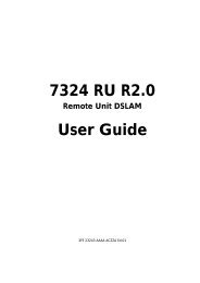
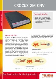
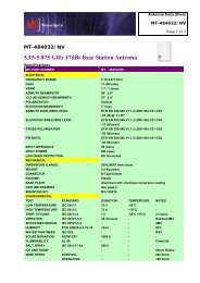
DIALOGIC APPLICATION NOTE1. Objective:This application note focuses on setting up a <strong>DataKinetics</strong> SIU & Host back to back with a PCCS6 system inorder to create a test harness for an <strong>SS7</strong> network. This app note is a supplemental to the <strong>DataKinetics</strong> SWmanuals and will attempt to point out any configuration difficulties that one may experience in setting up thisconfiguration. This test harness, once established, should be a good platform to reproduce and helpresolve any <strong>SS7</strong> customer issues. This will also provide an excellent development platform in order to do<strong>SS7</strong> application development.Prior to discussing the <strong>DataKinetics</strong> <strong>SS7</strong> products, it may be a good idea to review some basic terminologyand concepts about <strong>SS7</strong> architecture and the <strong>SS7</strong> protocol stack. If you are fairly comfortable with theseconcepts and wish to move ahead to the <strong>DataKinetics</strong> product specifics, go directly to Section 4.2. <strong>SS7</strong> Basic Terminology and Architecture2.1. Signaling Links<strong>SS7</strong> messages are exchanged between network elements over 56 or 64 kilobit per second (Kbps) bidirectionalchannels called signaling links. Signaling occurs out-of-band on dedicated channels ratherthan in-band on voice channels. Compared to in-band signaling, out-of-band signaling provides:• faster call setup times (compared to in-band signaling using multi-frequency (MF) signaling tones)• more efficient use of voice circuits• support for Intelligent Network (IN) services which require signaling to network elements withoutvoice trunks (e.g., database systems)• improved control over fraudulent network usage2.2. Signaling PointsEach signaling point in the <strong>SS7</strong> network is uniquely identified by a numeric point code. Point codes arecarried in signaling messages exchanged between signaling points to identify the source and destination ofeach message. Each signaling point uses a routing table to select the appropriate signaling path for eachmessage.There are three kinds of signaling points in the <strong>SS7</strong> network (Fig. 1):• SSP (Service Switching Point)<strong>Using</strong> <strong>DataKinetics</strong> <strong>SS7</strong> <strong>Products</strong> - Annette Donofrio Page 4Copyright Dialogic Corporation 1998, All Rights Reserved.The Name Behind the Voice
DIALOGIC APPLICATION NOTE• STP (Signal Transfer Point)• SCP (Service Control Point)Figure 1. <strong>SS7</strong> Signaling PointsSSPs are switches that originate, terminate, or tandem calls. An SSP sends signaling messages to otherSSPs to setup, manage, and release voice circuits required to complete a call. An SSP may also send aquery message to a centralized database (an SCP) to determine how to route a call (e.g., a toll-free 1-800/888 call in North America). An SCP sends a response to the originating SSP containing the routingnumber(s) associated with the dialed number. An alternate routing number may be used by the SSP if theprimary number is busy or the call is unanswered within a specified time. Actual call features vary fromnetwork to network and from service to service.Network traffic between signaling points may be routed via a packet switch called an STP. An STP routeseach incoming message to an outgoing signaling link based on routing information contained in the <strong>SS7</strong>message. Because it acts as a network hub, an STP provides improved utilization of the <strong>SS7</strong> network byeliminating the need for direct links between signaling points. An STP may perform global title translation,a procedure by which the destination signaling point is determined from digits present in the signalingmessage (e.g., the dialed 800 number, calling card number, or mobile subscriber identification number). AnSTP can also act as a "firewall" to screen <strong>SS7</strong> messages exchanged with other networks.Because the <strong>SS7</strong> network is critical to call processing, SCPs and STPs are usually deployed in mated pairconfigurations in separate physical locations to ensure network-wide service in the event of an isolatedfailure. Links between signaling points are also provisioned in pairs. Traffic is shared across all links in thelinkset. If one of the links fails, the signaling traffic is rerouted over another link in the linkset. The <strong>SS7</strong>protocol provides both error correction and retransmission capabilities to allow continued service in theevent of signaling point or link failures.3. The <strong>SS7</strong> Protocol Stack<strong>Using</strong> <strong>DataKinetics</strong> <strong>SS7</strong> <strong>Products</strong> - Annette Donofrio Page 5Copyright Dialogic Corporation 1998, All Rights Reserved.The Name Behind the Voice
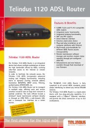
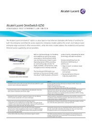
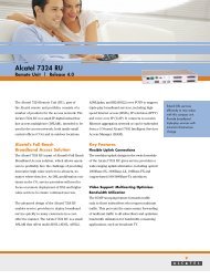
DIALOGIC APPLICATION NOTEThe hardware and software functions of the <strong>SS7</strong> protocol are divided into functional abstractions called"levels". These levels map loosely to the Open Systems Interconnect (OSI) 7-layer model defined by theInternational Standards Organization (ISO).Figure 2. The OSI Reference Model and the <strong>SS7</strong> Protocol Stack3.1. Message Transfer PartThe Message Transfer Part (MTP) is divided into three levels. The lowest level, MTP Level 1, is equivalentto the OSI Physical Layer. MTP Level 1 defines the physical, electrical, and functional characteristics of thedigital signaling link. Physical interfaces defined include E-1 (2048 kb/s; 32 64 kb/s channels), DS-1 (1544kb/s; 24 64kb/s channels), V.35 (64 kb/s), DS-0 (64 kb/s), and DS-0A (56 kb/s).MTP Level 2 ensures accurate end-to-end transmission of a message across a signaling link. Level 2implements flow control, message sequence validation, and error checking. When an error occurs on asignaling link, the message (or set of messages) is retransmitted. MTP Level 2 is equivalent to the OSI DataLink Layer.In some configurations the number of signaling links may exceed the capacity of a single PCCS6 board, orMTP2 entities may need to be distributed across multiple boards for sake of fault tolerance. In these<strong>Using</strong> <strong>DataKinetics</strong> <strong>SS7</strong> <strong>Products</strong> - Annette Donofrio Page 6Copyright Dialogic Corporation 1998, All Rights Reserved.The Name Behind the Voice
DIALOGIC APPLICATION NOTEconfigurations, the MTP3 entity may need to reside up on the Local Host or Local Server Module capable ofInter-Module communication.MTP Level 3 provides message routing between signaling points in the <strong>SS7</strong> network. MTP Level 3 reroutestraffic away from failed links and signaling points and controls traffic when congestion occurs. MTPLevel 3 is equivalent to the OSI Network Layer.MTP 3 provides three key functions: routing, message discrimination and distribution. MTP 3 is the one ofmost critical entities in the <strong>SS7</strong> protocol architecture and needs to maintain knowledge of the entire <strong>SS7</strong>network topology to ensure end-to-end transmission. Without this level of visibility, MTP 3 could not offercomplete route management services, signaling link management, load balancing and congestionmanagement.Each MTP 3 entity is assigned a Point Code address for message routing. A single MTP 3 entity is typicallyserviced by sets of subtending Message Transfer Part 2 (MTP 2) data link protocol entities organized asSignaling linksets. Signaling Links are organized as linksets to offer seamless switching of message load inthe event of link failures. Load balancing across Signaling linksets can only be performed within the samepoint code. For this reason, many applications may require MTP 3 to be Host resident.3.2. ISDN User Part (ISUP)The ISDN User Part (ISUP) defines the protocol used to set-up, manage, and release trunk circuits thatcarry voice and data between terminating line exchanges (e.g., between a calling party and a called party).ISUP is used for both ISDN and non-ISDN calls. However, calls that originate and terminate at the sameswitch do not use ISUP signaling.3.3. Telephone User Part (TUP)In some parts of the world (e.g., China, Brazil), the Telephone User Part (TUP) is used to support basiccall setup and tear-down. TUP handles analog circuits only. In many countries, ISUP has replaced TUP forcall management.3.4. Signaling Connection Control Part (SCCP)SCCP provides connectionless and connection-oriented network services and global title translation(GTT) capabilities above MTP Level 3. A global title is an address (e.g., a dialed 800 number, calling cardnumber, or mobile subscriber identification number) which is translated by SCCP into a destination pointcode and subsystem number. A subsystem number uniquely identifies an application at the destinationsignaling point. SCCP is used as the transport layer for TCAP-based services. Without SCCP, the smallestaddressable entity would be a point code. With SCCP, a subsystem (i.e. a user application) within a pointcode can be addressed.<strong>Using</strong> <strong>DataKinetics</strong> <strong>SS7</strong> <strong>Products</strong> - Annette Donofrio Page 7Copyright Dialogic Corporation 1998, All Rights Reserved.The Name Behind the Voice
DIALOGIC APPLICATION NOTE3.5. Transaction Capabilities Applications Part (TCAP)TCAP supports the exchange of non-circuit related data between applications across the <strong>SS7</strong> network usingthe SCCP connectionless service. Queries and responses sent between SSPs and SCPs are carried inTCAP messages. For example, an SSP sends a TCAP query to determine the routing number associatedwith a dialed 800/888 number and to check the personal identification number (PIN) of a calling card user.In mobile networks (IS-41 and GSM), TCAP carries Mobile Application Part (MAP) messages sentbetween mobile switches and databases to support user authentication, equipment identification, androaming.4. The <strong>DataKinetics</strong> Product LineDialogic has had a relationship with <strong>DataKinetics</strong> since 1994. Many Dialogic customers have integrated<strong>DataKinetics</strong> <strong>SS7</strong> products into their CT applications. Some of these solutions are currently deployed in thepublic network.Dialogic is reselling the following <strong>DataKinetics</strong> <strong>Products</strong>:• PCCS6 is an ISA-based <strong>SS7</strong> board solution.• SIU is an <strong>SS7</strong>-to-TCP/IP server solution.• <strong>SS7</strong> software stacks for TUP, ISUP, and TCAP.All of these products use the same architecture and <strong>SS7</strong> API.4.1. Specific Product Details4.1.1. Signaling Interface Unit (SIU)• An integrated, box-level solution that converts the <strong>SS7</strong> protocols to TCP/IP messages• Automatically distributes <strong>SS7</strong> messages to the appropriate voice response units (VRUs) basedon circuit identification code (CIC)• SIUs can be deployed in a load-sharing configuration to increase reliability• Single or dual E1/T1/V.35 interfaces per PCCS6 card present in SIU• <strong>SS7</strong> signaling can be extracted from an incoming E-1 or T-1 PCM port into the SIU and if thereare voice circuits also on that signaling link, they are passed out of the 2 nd E-1 or T-1 PCM porton the board. Alternatively, the signaling can be connected using V.35 serial links or on a PCMport with no voice circuits. Signaling information is automatically distributed by the SIU via aTCP/IP LAN to the host application platform. A portable interface library is provided which can beused on most UNIX and Windows NT® platforms. Two units can be configured to share thesame point code, providing fully resilient operation within a single point code. In normal<strong>Using</strong> <strong>DataKinetics</strong> <strong>SS7</strong> <strong>Products</strong> - Annette Donofrio Page 8Copyright Dialogic Corporation 1998, All Rights Reserved.The Name Behind the Voice
DIALOGIC APPLICATION NOTEoperation, signaling can be load-shared across the two units. If one unit fails, the remaining unithandles all signaling.• AC/DC power supplies• DOS, Windows NT, Solaris and SCO operating systems4.1.1.1. DSC1314.1.1.2. DSC2314.1.2. PCCS6• DS0s (CIC codes) controllable: DSC/131 – 4096• Signaling Links: DSC/131 – up to 6 signaling links (2 PCCS6 cards max.)• Maximum # of Link Sets: 4• Maximum call rate: DSC/131 – 25 calls/second• Maximum host connectivity: 16 Hosts.• Maximum # of circuit groups configurable: 128• DS0s (CIC codes) controllable: DSC/231 – 16384• Signaling Links: DSC/231 – up to 32 signaling links (12 PCCS6 cards max)• Maximum # of Link Sets: 4 (Max of 16 links/link set)• Maximum call rate: DSC/231 – 80 calls/second;• Maximum host connectivity: 32 Hosts.• Maximum # of circuit groups configurable: 648• An ISA card• One or two network interfaces (T1, E1, or V.35)• Up to 3 <strong>SS7</strong> signaling links• SCbus connector• TCAP software running on the PC-CS6 card• DOS, Windows NT, and SCO operating systems• DS0s (CIC codes) controllable: 64 or 256 depending on ISUP module downloaded.• Maximum # of circuit groups configurable: 128 (when ISUP running on host), 16 (when 256CIC’s), 4 (when 64 CIC’s).• Maximum call rate: ??? calls/second (Very much host processor dependent!)<strong>Using</strong> <strong>DataKinetics</strong> <strong>SS7</strong> <strong>Products</strong> - Annette Donofrio Page 9Copyright Dialogic Corporation 1998, All Rights Reserved.The Name Behind the Voice
DIALOGIC APPLICATION NOTE4.1.3. <strong>SS7</strong> Software• TUP - Telephony User Part• BT NUP• China TUP• French TUP (coming soon)• ISUP - Integrated Services User Part• ITU• ANSI• TCAP - Transactions Capabilities Application Part• ITU• ANSI• Most of the <strong>SS7</strong> software protocols are customizable.• New <strong>SS7</strong> software protocols are being added all the time.5. <strong>DataKinetics</strong> Software ArchitectureThe <strong>DataKinetics</strong> software architecture is very well described in the "System7 Software EnvironmentProgrammer's Manual". Excerpts of the manual are below. Please see the manual for complete details.5.1. IntroductionThe <strong>DataKinetics</strong> System7 product range is comprised of a number of portable software modules forthe realization of Signaling System Number 7 (<strong>SS7</strong>) protocol stacks. The System7 architecture ismulti-tasking, using message passing to communicate between tasks.Each module in the system is implemented as a separate task within the chosen operatingenvironment. A module implements either a layer within the protocol stack, a user part or some otherfunctional entity within the system. In general, a module supports multiple instances within a singleprocess (for example multiple links, multiple circuits or multiple transactions are each handled by asingle process).For software portability, each module makes a minimum demand on the host operating system.Most modules require just 5 functions to be provided by the operating system, these are required forinter-process communication and memory allocation. This approach makes the software easy to portto different platforms and operating environments. In addition, the use of message passing between<strong>Using</strong> <strong>DataKinetics</strong> <strong>SS7</strong> <strong>Products</strong> - Annette Donofrio Page 10Copyright Dialogic Corporation 1998, All Rights Reserved.The Name Behind the Voice
DIALOGIC APPLICATION NOTEtasks, and therefore protocol layers, means that it is possible for different layers to run on differentprocessors if required.All that is required to port the System7 product to a new environment is an implementation of the 5library functions tailored to the chosen operating system. These functions are available as standardproducts for a number of popular operating systems.NOTE: There are additional library calls available in the in the event that dual SIU’s are being used(i.e. GCT_set_instance() & GCT_get_instance() ).5.2. Basic ConceptsThis section introduces the basic System7 concepts and terminology used throughout the<strong>DataKinetics</strong> documentation suite.5.2.1. ModulesA module is an implementation of a particular layer in the protocol stack (eg. MTP2, MTP3),a particular user part (eg. ISUP, SCCP) or a collection of other functionality which fitstogether as a logical entity. A module may be part of the System7 product range or a Usersuppliedmodule.Each module in the system runs as a separate task, process or program (depending on thetype of operating system). The module is identified by a Module Identifier andcommunicates with other modules in the system by sending Messages to a MessageQueue belonging to the destination module. A set of Library Functions is the only operatingsystem specific code used by a module.A module handles multiple instances of the functional entity associated with the module (eg.MTP2 module handles multiple signaling links, the MTP3 module handles multiple link setsand multiple routes, the ISUP module handles multiple circuits).5.2.2. Module IdentifiersEach module has a module identifier (module_id) which is a logical number in the range 0 to255. It is used to identify modules within the system for the purposes of inter-processcommunication. To send a message to another process the sending module uses themodule identifier of the destination process. To receive a message from a modules ownmessage queue it uses it’ s own module identifier.Some modules operate with a fixed module identifier while others allow the module identifierto be specified at run-time. The module identifiers of other modules with which a module willcommunicate is usually a run-time configuration option. The module identifier is a logicalvalue, it is not the same as the task_id or process id (pid) which is usually allocatedautomatically by the operating system when a process is created.The inter-process communication mechanism usually uses the module identifier as an indexto an array of message queue pointers to provide an efficient mechanism to quickly access<strong>Using</strong> <strong>DataKinetics</strong> <strong>SS7</strong> <strong>Products</strong> - Annette Donofrio Page 11Copyright Dialogic Corporation 1998, All Rights Reserved.The Name Behind the Voice
DIALOGIC APPLICATION NOTEthe correct message queue. This feature can also be used to allow messages destined for aparticular module to be re-directed to an alternative message queue belonging to anothermodule.The re direction mechanism is used when messages need to be transferred to another boardin the system. Messages for all processes that run on the other board are redirected to aspecial local module which handles inter-board message passing. Other modules within thesystem do not need to know whether the modules with which they communicate are runninglocally or not.5.2.3. MessagesModules communicate by sending messages to other modules in the system. There arethree types of messages used within the System7 protocol software (MSG, T_FRAME andR_FRAME). (However T_FRAMEs and R_FRAMEs are only used on embedded processorsby modules running on the same processor as the physical interface). For this reason thisdocument refers in detail only to the use of the MSG message structure.The MSG message is a ‘ C’ structure containing a fixed format header field (which iscommon also with T_FRAMEs and R_FRAMEs) and a buffer for variable length parameterdata.The message header contains a message type field, which serves to identify the meaning ofthe message and the format of the variable parameter area. The id field identifies to whichinstance of the entity handled by the module the message applies (eg the link id or the circuitid etc). The src and dst fields are the source and destination module identifiers which mustbe entered by the sending module prior to sending the message. The rsp_req field is usedby the sending module to solicit a confirmation that the message has been processed by thedestination process. When a confirmation is requested, the destination module (afterfinishing processing the message) enters a value in the status field of the message (usuallyzero to imply success or non-zero otherwise) and sends the message back to the sourcemodule.5.2.4. Message QueuesEach module in the system has a single message queue, which is used by other modules tosend messages to the module. A message queue is a system buffer which stores messages(usually by reference) in first-in, first-out order.Messages are read out of the message queue by the receiving module which typically waitsuntil there is a message available and reads it, it then processes the message and waits untilthe next message is available. All input to the module is through its message queue.The fact that the software is modularized in such a way allows applications to be scalable from asingle board configuration to a multiple SIU configuration without modifying the application. Thechanges that are required to move to a higher density solution are configuration related.<strong>Using</strong> <strong>DataKinetics</strong> <strong>SS7</strong> <strong>Products</strong> - Annette Donofrio Page 12Copyright Dialogic Corporation 1998, All Rights Reserved.The Name Behind the Voice
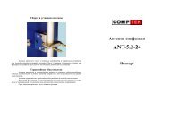
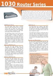
DIALOGIC APPLICATION NOTE6. Software Deliverables from <strong>DataKinetics</strong>SoftwareDeveliverablePCCS6PackageDevelopmentUser Part DevelopmentPackageSystem where SWResidesPCCS6 SystemPCCS6 System & SIUHostSoftware DescriptionContains the device driver, header files and libraryfunctions for use by an application, a number ofexecutables to be run as part of the System7environment, and a utility program to configure theprotocol SW.Contains example source code to illustrate thetechniques used for interfacing with the System 7software modules.OS Specific Host SW SIU Host Contains a number of executable programs andlibraries or C-source files that are linked with theusers’ application.System7 Binary Disks PCCS6 System Contains the code file, which is downloaded to theboard at run-time by the driver program. Codefiles for PCCS3 have a file suffix .dc1 while codefiles for PCCS6 use .dc2.7. High Level Architecture of SIUPCCS6 System Setup<strong>Using</strong> <strong>DataKinetics</strong> <strong>SS7</strong> <strong>Products</strong> - Annette Donofrio Page 13Copyright Dialogic Corporation 1998, All Rights Reserved.The Name Behind the Voice
DIALOGIC APPLICATION NOTESSP or SCPSSP or SCPDialogic Voice Lines(if present)SIU Host - moe(IP: 146.152.64.22)Terminal to control SIU(RS/232)<strong>SS7</strong> NetworkT1 Crossover cablePCCS6 System - ss7(IP: 146.152.64.33)DSC/131 - SIU(IP: 146.152.64.25)Dialogic LANFigure 3. The High Level Architecture of SIU PCCS6 System Setup8. Configuring the PCCS6 SystemTake the following steps to get a <strong>DataKinetics</strong> PCCS6 configuration working:1) Set the I/O base address on the board (SW1)2) Set the IRQ jumpers on the board3) Make sure that daughtercard is set to either either T1 or E1 position (This is not documented in<strong>DataKinetics</strong> manuals!)4) Install the <strong>DataKinetics</strong> software (See “Installing the PCCS6 Development Package for WindowsNT” ,“Installing the User Part Development Package” and “Installing the System7 Binary disks”below).5) Copy the PCCSXDVR.SYS (the <strong>DataKinetics</strong> driver) to the \WINNT\system32 directory (see“Installing the Device Driver”).6) Copy GCTNT.DLL (the <strong>DataKinetics</strong> DLL) to \WINNT\system32 directory (see “Installing the DeviceDriver”).<strong>Using</strong> <strong>DataKinetics</strong> <strong>SS7</strong> <strong>Products</strong> - Annette Donofrio Page 14Copyright Dialogic Corporation 1998, All Rights Reserved.The Name Behind the Voice
DIALOGIC APPLICATION NOTE7) Enable the driver (see "Activating the Device Driver" below)8) Verify that the driver has been enabled (see "Activating the Device Driver" below)9) Change the Startup Mode of the driver to "Automatic".10) Modify the configuration files to reflect your configuration (see "Configuration Files" below)11) Execute the BIN\gctload program to read the system.txt configuration file and "FORK" theappropriate executable files specified in the configuration files.12) Make sure that the signaling link has been activated (see “Activating the <strong>SS7</strong> Link” ).8.1. Installing the PCCS6 Development Package for Windows NTThe PCCS Development Package for Windows NT is distributed on a DOS format disk. The installationprocedure essentially involves copying the files onto your development system.In order to set up the PCCS6 system, first create a new directory to serve as the root directory for theSystem7 software.mkdir c:\system7Then copy the contents of the PCCS Development Package into this directory according to the followingsub-directory structure.<strong>Using</strong> <strong>DataKinetics</strong> <strong>SS7</strong> <strong>Products</strong> - Annette Donofrio Page 15Copyright Dialogic Corporation 1998, All Rights Reserved.The Name Behind the Voice
DIALOGIC APPLICATION NOTEThe sub-directories and their contents are as follows:binrunlibsrc\incsrc\exampleDirectory containing executable programs as follows:• Windows NT device driver: pccsxdvr.sys,• Dynamic link library: gctnt.dll,• Interface w/device driver for message passingto/from board and downloading SW to board:ssd.exe• Board installation utility: pccsxcfg.exe,• System7 environment executables: gctload.exe,tim_nt.exe and tick_nt.exe.• Protocol software configuration utility: s7_mgt.exeand example executables: mtpsl.exe and upe.exe.Directory containing system configuration file system.txtand Protocol configuration file config.txt, as well as the*.dc2 code file. This is the directory from which thesoftware should be run.Directory containing library files *.lib for linking with theusers application: gctnt.lib & genlib.lib.C header files required by an application.Example source code to activate or deactivate an <strong>SS7</strong>signaling link: mtpsl.c and an example of how tointerface to MTP3 upe.c.8.2. Installing the User Part Development PackageCopy the contents of the User Part Development Package distribution disk into the system7\src directorymaintaining the sub-directory structure.8.3. Installing the System7 Binary DiskCopy the appropriate Binary code file (*.dc2) that you want downloaded to your PCCS6 card into the \rundirectory. The title of the file tells which user parts (if any) in addition to the <strong>SS7</strong> Message Transfer Part(MTP) (which is always included) are included in the code file. The title of the file refers to the highest <strong>SS7</strong>Protocol layer included in the code file including all sub layers. Refer to Figure 3 to see which layers areconsidered sub-layers.For Example:mtp.dc2:includes only MTP<strong>Using</strong> <strong>DataKinetics</strong> <strong>SS7</strong> <strong>Products</strong> - Annette Donofrio Page 16Copyright Dialogic Corporation 1998, All Rights Reserved.The Name Behind the Voice
DIALOGIC APPLICATION NOTEisup.dc2:tup.dc2:tcap.dc2:includes ISUP & MTPincludes TUP & MTPincludes TCAP, SCCP & MTP8.4. Installing the Device DriverWhen installing a PCCS6 board, there is one file (pccsxdvr.sys) that is loaded into the \BIN directory thatmust be moved into the \WINNT\system32 directory. This is the device driver file. This file must reside inthe system32 directory for the <strong>DataKinetics</strong> software to operate properly. Also, a copy of the \LIB\gctnt.dllfile must be copied to the system32 directory.8.5. Activating the Device DriverOnce the PCCSXDVR.SYS file has been copied to the correct directory, it must be activated. ThePCCSXCFG.EXE program must be used to do this. The PCCSXCFG.EXE program adds the device driverto the system. Example instantiation of this command to add the device driver is as follows:C:\system7\BIN> pccsxcfg -n1 -p0x200 -m0xd0000 add c:\winnt\system32\pccsxdvr.sysThe parameters are as follows:-n1 number of boards-p0x200i/o port (each board uses 4 portsfrom and including the first)-m0xd0000memory address (each board usesthe same 4K block)add"add" the device driverc:\winnt\system32\pccsxdvr.sysIf the command was successful, the following will be printed to the screen:"PCCS6 board 0 : memory 0xd0000 ioport 0x200"If this is not displayed, something did not get installed correctly. In most cases, this is an I/O or memoryconflict. Check the NT Diagnostics and verify that the board is being loaded in an unoccupied location (usec:\winnt\system32\winmsd.exe). Also, check Event Viewer for more details on failure! The driver must thenbe removed and the "add" process re-tried. To remove the driver, execute the program as follows:C:\system7\BIN> pccsxcfg removeOnce the device has been activated using this command, it can be verified by using Control Panel ->Devices and locating the device PCCS. This device should say "Manual" and "Started". If so, the devicehas been started successfully. Now, the devices Startup Mode should be changed to "Automatic" so thisdevice is always stared upon a restart of NT.<strong>Using</strong> <strong>DataKinetics</strong> <strong>SS7</strong> <strong>Products</strong> - Annette Donofrio Page 17Copyright Dialogic Corporation 1998, All Rights Reserved.The Name Behind the Voice
DIALOGIC APPLICATION NOTENOTE: Activating the driver only has to be done once.8.6. <strong>DataKinetics</strong> PCCS6 Environment Executable ProgramsOnce the installation of the software is complete and the driver is successfully activated, we can beginsetting up the <strong>SS7</strong> link. There are several executable programs which must be run to get a system working.Here is a list of executables needed in PCCS6 configurations and what they mean:8.6.1. S7_MGT.EXES7_MGT.EXE derives configuration parameters from the config.txt text file and sends protocolconfiguration messages to all the <strong>SS7</strong> software modules running. These messages configure the <strong>SS7</strong>protocol. This process is optional (but recommended). As an alternative to using it, the user can alsoperform protocol configuration by sending messages directly to other modules in the system.8.6.2. SSD.EXESSD.EXE is the process, which interfaces with the device driver for passing messages to and from theboard and for downloading SW.8.6.3. TIM_NTProcess to receive periodic tick notification from the tick_nt and handle protocol timers for all otherprocesses. This executable is not used by user applications, but is required by the <strong>DataKinetics</strong> internalsoftware.8.6.4. TICK_NTProtocol timer process to send periodic “tick” notification to the tim_nt process which in turn handlesprotocol timers. This executable is not used by user applications, but is required by the <strong>DataKinetics</strong>internal software.8.7. Activating the <strong>SS7</strong> LinkThe system environment is created and all protocol modules started by the gctload.exe program.8.7.1. GCTLOAD.EXEThe GCTLOAD.EXE program is run once all the configuration files are setup correctly. GCTLOAD.EXEreads through the system.txt file, sets up the software environment, then "forks" the executables specified inthe system.txt file. Typically this program is run from a batch file located in the run directory. For examplerun.bat files, refer to Appendix A for PCCS6 System & Appendix C for SIU Host.Once the system environment is initialized and all environmental executable processes are run, it is nowtime to “Activate the <strong>SS7</strong> Link” from. There is a utility called mtpsl, which is included for the user to easilyactivate the link. The format of the mtpsl utility is:<strong>Using</strong> <strong>DataKinetics</strong> <strong>SS7</strong> <strong>Products</strong> - Annette Donofrio Page 18Copyright Dialogic Corporation 1998, All Rights Reserved.The Name Behind the Voice
DIALOGIC APPLICATION NOTEmtpsl eg: mtpsl ACT 0 0NOTE: mtpsl can not be run from within the system.txt file. It must be run from the command line.The mtpsl.c sample code located in src\example is provided to show users how to send messages to MTP3to activate and deactivate links from within the user application. It is expected that eventually the user willincorporate this example code into their own application to activate the link at initialization.9. Configuring the SIU & SIU Host SystemsTake the following steps to get a <strong>DataKinetics</strong> SIU & SIU Host configuration working:1) Install <strong>DataKinetics</strong> software (See “Installing the OS Specific Host SW” and “Installing the User PartDevelopment Package” below)2) Connect either a dumb terminal to the SIU using the serial (RS232) connector or you can telnetacross the network to gain access to the SIU to edit config.txt and system.txt. A variety of terminalemulation programs, which emulate VT100 terminal type, will work.NOTE #1: The initial time that you configure the SIU, the IP address will not be set up correctly sotelnet will not work. For initial setup, a dumb terminal with a null-modem serial cable is required.NOTE #2: The SIU is not configured to allow access to a machine from another subnet. You musttelnet from the same subnet as the SIU in order to configure that system. Also, the host must be onthe same subnet as the SIU.3) Modify the etc/hosts file on the SIU to reflect the correct IP address for the SIU.NOTE: Make sure that’s the same IP address that is entered in the “FORK_PROCESS rsicmd.exe”line in the host system.txt file!4) Reboot the SIU for the IP address to take affect.5) "ping" the IP address from the "host" machine on the LAN (must be on same subnet!) to verify thatthe machine can talk to the SIU. Modify the configuration files to reflect your configuration (see"Configuration Files" below). If the host machine cannot "ping" the SIU, there may be somethingphysically wrong with the LAN setup. Check cables, etc.6) Execute the BIN\gctload program from the host machine to read the system.txt file on the host and"FORK" the appropriate executable files specified. In an SIU configuration, the <strong>SS7</strong> link specificconfiguration is only resident on the SIU itself since that is where the <strong>SS7</strong> cards reside, so the hostonly has a system.txt file and no config.txt file. For example configuration files, refer to Appendix Bfor SIU files and Appendix C for SIU Host files.9.1. Installing the OS Specific Host SWThe Win NT Host SW is distributed on a DOS format disk. The installation procedure essentially involvescopying the files onto your development system.<strong>Using</strong> <strong>DataKinetics</strong> <strong>SS7</strong> <strong>Products</strong> - Annette Donofrio Page 19Copyright Dialogic Corporation 1998, All Rights Reserved.The Name Behind the Voice
DIALOGIC APPLICATION NOTEIn order to set up the SIU Host system, first create a new directory to serve as the root directory for theSystem7 software.mkdir c:\system7Then copy the contents of the Win NT Host SW into this according to the following sub-directory structure.The sub-directories and their contents are as follows:binrunlibsrcDirectory containing executable programs as follows:System7 environment executables: gctload.exe, rsi.exe,rsi_lnk.exe, rsicmd.exe, s7_log.exe, s7_play.exe andsiucmd.exe.Directory containing system configuration file system.txtand run.bat This is the directory from which the softwareshould be run.Directory containing library file for linking with the user’sapplication: gctlib.lib.Directory where the User Part Development package willbe installed.9.2. Installing the User Part Development PackageCopy the contents of the User Part Development Package distribution disk into the system7\src directorymaintaining the sub-directory structure.9.3. <strong>DataKinetics</strong> SIU & SIU Host Environment Executable Programs9.3.1. RSI.EXEThis program manages the remote socket interface. It manages the routing of messages between the hostand SIU(s).9.3.2. RSI_LNK.EXEThis program is basically a pipe between the application and the SIU. It utilizes the TCP/IP interface andhides the TCP/IP specifics from the application.9.3.3. RSICMD.EXEThis program establishes the initial TCP/IP communication between the host PC and the SIU. Allsubsequent messages from the host to the SIU are sent using the RSI.EXE explained below. The TCP/IPaddress of the SIU is passed in as an argument to this program.<strong>Using</strong> <strong>DataKinetics</strong> <strong>SS7</strong> <strong>Products</strong> - Annette Donofrio Page 20Copyright Dialogic Corporation 1998, All Rights Reserved.The Name Behind the Voice
DIALOGIC APPLICATION NOTE9.3.4. SIUCMD.EXEThis program allows the user to issue SIU management commands as text on the host terminal to controlan SIU.9.3.5. S7_LOG.EXEThis program is a task that receives status and management indication messages from the SIU anddisplays these as text on the application console.9.3.6. S7_PLAY.EXEThis program reads message contents from an ASCII text file (in a defined format) and sends thesemessages to the SIU.9.4. Activating the <strong>SS7</strong> LinkThe system environment is created and all protocol modules started by the gctload.exe program.9.4.1. GCTLOAD.EXEThe GCTLOAD.EXE program is run once all the configuration files are setup correctly. GCTLOAD.EXEreads through the system.txt file, sets up the software environment, then "forks" the executables specified inthe system.txt file. See "Configuration Files" below for details on the system.txt file. TypicallyGCTLOAD.EXE is run from a batch file located in the run directory. For an example SIU Host run.bat file,refer to Appendix C.10. Configuration FilesThere are 2 configuration files used when setting up the software for a <strong>DataKinetics</strong> system: system.txt andconfig.txt.NOTE: Example config files for a PCCS6SIU configuration are in Appendices A-C.10.1. system.txtThe system.txt file specifies how the <strong>DataKinetics</strong> software environment is set up. This is NOT to say the<strong>SS7</strong> specific software, but the software that allows user applications to talk to the <strong>DataKinetics</strong> hardware.The system.txt file is located in the \RUN directory on the SIU Host and PCCS6 machines and is present in/home/dklsiu on the SIU. The easiest way to understand the operation of the <strong>DataKinetics</strong> software is tothink of each item as a module. Each module can run either in the host PC or on the <strong>DataKinetics</strong> hardware(PCCS6 card or SIU). This is true of all software modules from the MTP3 level and up. Each module usesinter process communication to send information to other modules.<strong>Using</strong> <strong>DataKinetics</strong> <strong>SS7</strong> <strong>Products</strong> - Annette Donofrio Page 21Copyright Dialogic Corporation 1998, All Rights Reserved.The Name Behind the Voice
DIALOGIC APPLICATION NOTEEach module that runs is assigned an identifier, called the module ID. The system.txt file creates thosemodule ID’s.The system.txt file contains 3 major sections:10.1.1. LOCALThe LOCAL section assigns module ID's for the modules that will run in the host machine. The hostmachine is the computer where the application is running. By placing the modules in this section it alsoguarantees that the queues for incoming messages (from other processes) will also be created.10.1.2. REDIRECTThe REDIRECT section redirects messages from one module to another. For example: If you REDIRECTmessages from your application to SSD.EXE, that means that the messages will be sent to the board. Ifyou REDIRECT messages from your application to RSI.EXE, they will be sent (via TCP/IP) to the SIU.10.1.3. FORK_PROCESSThe FORK_PROCESS section actually executes programs. This is where each of the modules identified inthe previous sections are actually run.10.2. config.txtThe config.txt file specifies the <strong>SS7</strong> link's connection characteristics. Just like the isxxx.prm files inDialogic ISDN configurations, the config.txt file specifies the details of the <strong>SS7</strong> interface. The config.txt filecontains multiple sections. In a PCCS6 configuration, the config.txt file is located on the host machine inthe \RUN directory. In an SIU configuration, this file is located on the SIU itself in /home/dklsiu. This filemust be modified by 'telnet'ing into the SIU machine and editing the file. Remember that the SIU has itsown operating system (QNX) that uses a 'vi' editor. Depending on whether a PCCS6 card is beingconfigured or an SIU, the config.txt file will contain different sections.10.2.1. PCCS6 Configurations:Below are the following configuration characteristics that are defined in the config.txt with regards to aPCCS6 configuration.10.2.1.1. Physical ConfigurationThe PCCS6_BOARD command identifies the characteristics of the card itself. Most notable items in thiscommand include the clock source for the board, how many interfaces are contained on the board and whatfirmware file to download to the board.10.2.1.2. MTP ConfigurationThis section defines the characteristics of the MTP layers. For example, the linkset, local point code andadjacent point code are defined here. In a back to back configuration, it is very important to verify that theLocal Point Code on one side of the connection is different than the Local Point Code on the other side.<strong>Using</strong> <strong>DataKinetics</strong> <strong>SS7</strong> <strong>Products</strong> - Annette Donofrio Page 22Copyright Dialogic Corporation 1998, All Rights Reserved.The Name Behind the Voice
DIALOGIC APPLICATION NOTEAlso, for a back to back configuration verify that the DPC (Destination Point Code) and Adjacent Point Codeon one side matches the Local Point Code on the other side.NOTE: In the MTP_ROUTE command, the user part mask is a 16 bit value with bit n (n=0..15) set to allowthe route to be used for messages with the following SI (service indicators). The SI’s are defined as follows:SCCP = 3 (0x8)TUP = 4 (0x10)ISUP = 5 (0x20)Important NOTE #1 for ANSI Operation: The MTP_CONFIG line in config.txt specifies how the Layer 2link should be set up. The ‘sub-service field” argument of MTP_CONFIG, which is 8 by default, must be setto 0xb for ANSI T1. This is NOT documented in the manuals. This argument is a bit field which specifiesmessage priorities, and must be set a certain way for ANSI T1 (ITU E1 does not prioritize message, whichis why they are mostly zero). Leaving the sub-service field at the default of 8 has the effect under T1, ofgiving highest priority to call setup messages, which ANSI dictates should have the lowest priority, and ofgiving zero priority to all other messages.Important NOTE #2 for ANSI Operation: Also in MTP_CONFIG, the “Options” bit field, which is set to allzeroes by default, must be set to 0xf00. Bits 8 & 9 specify ANSI operations, as documented in the manuals.Bits 10 & 11 operate somehow with the sub-service field to define message priorities and must be set forANSI T1 operations.10.2.1.3. ISUP ConfigurationThis section defines the ISUP characteristics. Point codes, CIC codes, etc. The Point Codes in this sectionmust match those in the MTP Configuration section.Important NOTE #3 for ANSI Operation: Each <strong>SS7</strong> user part has its own configuration command inconfig.txt. I’m only familiar with ISUP_CONFIG, however the “Options” field of ISUP_CONFIG, which is abit field, must have bits 8 & 9 set in order to enable ANSI compliant operations. These bits are zero bydefault.10.2.2. SIU Configurations:In an SIU configuration, the config.txt file contains all the same information in the PCCS6 configurationplus the following sections:10.2.2.1. SIU CommandsThis defines how many SIU's are in the system. A second SIU is typically configured for redundancy.10.2.2.2. Cross ConnectionsThis section maps the inbound B channels/tslots on one PCM port to the outbound B channels/tslots on theother PCM port, while the SIU strips off signaling information, which is sent to the host(s) via TCP/IP.NOTE: When enabling a T1 signaling link, it is important to comment our references for T1 timeslots 25-32in the MVIP_XCON section. You must also reset bits 25-32 of the “CIC Mask” argument of allISUP_CFG_CCTGRP command lines. By default this mask is 0x7fff7fff, it must be changed to 0x00ff7fff.<strong>Using</strong> <strong>DataKinetics</strong> <strong>SS7</strong> <strong>Products</strong> - Annette Donofrio Page 23Copyright Dialogic Corporation 1998, All Rights Reserved.The Name Behind the Voice
DIALOGIC APPLICATION NOTEIn a multiple host, single SIU configuration, the following are important points:1) The <strong>DataKinetics</strong> software is designed to have a single point of contact for Management and Servicetypes of messages (i.e. any messages received from MTP3 and below). So, when the second hostmachine runs GCTLOAD to activate the link, all that will be seen is a "Link Up" message and nothingelse. This is because the messages that Host 1 sees are Management messages from MTP2 andMTP3. Host 2 will not see these messages.2) You might at that point ask, "How is Host 2 supposed to know that the link is established and I can beginmaking calls?” The answer is, the application code is responsible for informing each host of what ishappening with the link. The management messages are sent to a single place in your system to belogged and controlled by one machine. That machine then informs all the other hosts (you could haveup to 32 hosts with a DSC231 model SIU and 16 hosts with a DSC131 model SIU).3) There must be one ISUP_CFG_CCTGRP command in the configuration file for every "span" in theentire system. That means that even the spans that do not have a D-Channel and are not directlyconnected to the SIU must have an entry in this file. If there are multiple hosts, theISUP_CFG_CCTGRP command instructs the SIU as to where to send the messages for those particularcircuits.4) The base_cic is from the switch's perspective. So, if you are connected to the same switch for bothlinks, the will never be the same number. BUT, if you are connected to multiple switches,the could be the same number. The is a logical number used from the SIU'sperspective. That means that it will never be the same number and should be incremented for everycircuit entry in the configuration file (i.e the = 0 through total_circuits-1).<strong>Using</strong> <strong>DataKinetics</strong> <strong>SS7</strong> <strong>Products</strong> - Annette Donofrio Page 24Copyright Dialogic Corporation 1998, All Rights Reserved.The Name Behind the Voice
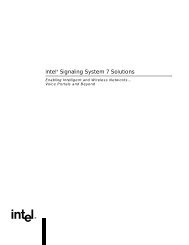
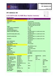
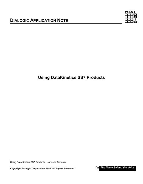
DIALOGIC APPLICATION NOTE11. SIU/PCCS6 Back to Back ConfigurationThe following diagram illustrates a back to back configuration using an SIU on one side and a PCCS6 cardon the other. Configuration files are given to show exactly how to configure this setup in Appendices A-C.These diagrams illustrate software and hardware modules in this configuration. Hardware modules areshown with black shadowing, software modules with gray.The following diagram shows an example of the software environment. Notice that the modules in thepicture map not only to the module ID's in the system.txt files located in Appendix A (for PCCS6 system)and Appendix C (for SIU Host system), but also in the FORK_PROCESS section where these process areactually executed.Host PCPCCS6 System<strong>SS7</strong>pongmod ID:0x1dS7_logmod ID:0xef<strong>SS7</strong> Link<strong>SS7</strong>pong -imod ID: 0x2dTICK_NT.EXEmod ID: 0x00RSImod ID: 0xb0Ethernet -TCP/IP LinkSSD.exemod ID:0x20TIM_NT.EXEmod ID: 0x00RSICMDmod ID: 0xfdSIUPCCS6CardISUP, MTP3, MTP2running on the SIUISUP,MTP3,MTP2 running onthe BoardFigure 4. SIUPCCS6 Back to Back Configuration<strong>Using</strong> <strong>DataKinetics</strong> <strong>SS7</strong> <strong>Products</strong> - Annette Donofrio Page 25Copyright Dialogic Corporation 1998, All Rights Reserved.The Name Behind the Voice
DIALOGIC APPLICATION NOTE12. Things to Check when there are Problems1) Verify that PCCS6 board is set to T1 or E1 mode with the daughtercards. NOTE: This is not documented!For SIU’s, rather than opening up system, send email to support@datakinetics.co.uk with SIU serialnumber and they will tell you how the SIU was configured.2) Make sure that a cross over cable is used for the <strong>SS7</strong> link. Also, when setting up two SIU’s in dualredundancy mode, a cross over cable must be used between the two SIU’s.3) Make sure that each user app is compiled and linked with the appropriate development package that it willbe run with. The libraries are not binary compatible between PCCS6 Development Pkg and OS SpecificSIU Host SW!E.g. An application compiled and linked with the PCCS6 development package will not run on the SIU hostor visa versa!4) Check clocking! Ensure that one end is providing clock and one end is looking to the <strong>SS7</strong> network forclock. Can not have both ends providing or both looking to the network for clock.5) It is helpful to put ‘-d’ for debug in the following FORK_PROCESS commands to get a verbose descriptionof what is going on. NOTE: This is not documented.On the PCCS6 System:In run.bat: “gctload –d”In system.txt:“SSD.EXE –d”“S7_mgt.exe –d”On the SIU Host System:In run.bat: “gctload –d”6) The system.txt file on the SIU should not need to be modified. The only exception to this is when you needto enable protocol verification between the SIU and the host machine for debugging purposes. You willwant to add the -nv option in both the SIU and the SIU host’s system.txt files, as follows:FORK_PROCESS..\BIN\RSI.EXE -pfifo -r..\BIN\RSI_LNK.EXE -nvThis option enables protocol verification between the SIU and the host machine. The -nv option should beremoved from BOTH the SIU system.txt file and the SIU host system.txt file once the verification has beendone.7) If the <strong>DataKinetics</strong> <strong>SS7</strong> Management process on the SIU crashes with the very helpful error message:“***S7MGT FAILED***”, then comment out all timeslots above 24 in the MVIP_XCON commands inconfig.txt<strong>Using</strong> <strong>DataKinetics</strong> <strong>SS7</strong> <strong>Products</strong> - Annette Donofrio Page 26Copyright Dialogic Corporation 1998, All Rights Reserved.The Name Behind the Voice
DIALOGIC APPLICATION NOTE13. Running a sample application like ss7pong.exeNOTE #1: ss7pong.exe is an internal demo created from the CTU demo. It is not delivered with any of the<strong>DataKinetics</strong> packages. To obtain a copy of this demo go to: \\donofria2\ss7pong. As part of the “User PartDevelopment Package” there is a demo called CTU, which is very similar to ss7pong.exe. The CTU demo isan example call control application that runs above a telephony user part. When an incoming call is set up,CTU will answer this call and attempt an outgoing call on the next circuit.The ss7pong.exe demo is very useful in proving a connection between two machines and in also learning thefunctions to prove one. It sends the following ISUP messages back and forth until you hit control-C. (IAM,ACM, ANM, REL and RLC). More importantly, it does not require any voice processing HW in order to verifythe <strong>SS7</strong> link. It’s an excellent starting point.The side that initiates (i.e. sends the first IAM message) must be started with the –i option. Only one call isactive at a time, and the two sides take turns initiating the call.When terminating ss7pong, to keep the ISUP modules happy, ss7pong should be canceled first on the sidethat initiated the first call (that is, ss7pong -i). Cancel it immediately after this side sends an REL message(releasing a call that the other side had initiated), but before it sends its next IAM. There is a one-secondpause between calls for this purpose. Then, cancel ss7pong on the other side.Gotchas:The initiating side running ss7pong.exe with the “-i” option, is hardcoded to module id 0x2d. <strong>Using</strong> the –moption to reset the module id has no effect. The non-initiating side defaults to module id 0x1d, however thisside can be overridden by the –m command line option.NOTE #2: Make sure that if you change the module id using the –m option that the same module id is presentin the FORK_PROCESS line in system.txt.The ss7pong.exe does not activate the signaling link. For this reason, mtpsl must be run prior to running thedemo. mtpsl must be run from the command line, not from within system.txt.<strong>Using</strong> <strong>DataKinetics</strong> <strong>SS7</strong> <strong>Products</strong> - Annette Donofrio Page 27Copyright Dialogic Corporation 1998, All Rights Reserved.The Name Behind the Voice
DIALOGIC APPLICATION NOTEAppendix A14. PCCS6 Files14.1. config.txt* Example config.txt for the System7 protocol configuration.** Edit this file to reflect your configuration.** Physical Configuration* ----------------------* board id is a logical number. The driver accesses the board at the i/o port id* and add a board at the offset. its trying to start a board at 204 . The i/o ports and the* board ID's map 1-1 so board 0 = ox200* up to 16 cardsPCCS6_BOARD 0 0 0 0x0002 isup76.dc2* ^ ^ ^ ^ ^*PortID -------------' | | | |*BOARDID -------------' | | |*NUM_PCM ----------------' | |*FLAGS -------------------------' |*Board code file -------------------------'** MTP Configuration* -----------------*MTP_CONFIG 1 0xb 0x0f00* ^ ^ ^* Local PC -------' | |* SSF ------------------' |* Options -------------------'*MTP_LINKSET 0 0x2 2 0x0000* ^ ^ ^ ^* Linkset ID ------' | | |* Adj PC ---------------' | |* Max number of links --' |* Flags -----------------------------'*<strong>Using</strong> <strong>DataKinetics</strong> <strong>SS7</strong> <strong>Products</strong> - Annette Donofrio Page 28Copyright Dialogic Corporation 1998, All Rights Reserved.The Name Behind the Voice
DIALOGIC APPLICATION NOTEMTP_LINK 0 0 0 0 0 0 0x10 0x10 0x06* ^ ^ ^ ^ ^ ^ ^ ^ ^* LinkID ------' | | | | | | | |* Linkset ID -----' | | | | | | |* Link ref ------------' | | | | | |* SLC ----------------------' | | | | |* BPOS -----------------------' | | | |* BLINK ---------------------------' | | |* STREAM ----------------------------' | |* TIMESLOT ----------------------------------' |* FLAGS -------------------------------------------------'*MTP_ROUTE 2 0 0x0020 * each user part is assigned a unique number* ^ ^ ^* DPC------------' | |* Linkset ID --------' |* UP enable ------------'* tup = 4* sccp = 3* isup = 5* This is the number of bit switches to enable the right user parts. so in our* example above, we are setting bit 5 to 1 for ISUP user part.*** This is normally used if someone is supplying their own user part.*MTP_USER_PART 0x0a 0x23* ^ ^* Service Ind ----------' |* Mod ID --------------------------'*** ISUP Configuration* ------------------** Must enable ISUP's user part*ISUP_CONFIG 1 0xb 0x2d 0x0734 * 0x0001 0x0018* ^ ^ ^ ^ ^ ^*Local PC --------' | | | | |*SSF -------------------' | | | |*User ID ----------------------' | | |*Options ------------------------------' | |*Number of circuit groups (optional) -----' |*Number of circuits (optional) ---------------------------'**<strong>Using</strong> <strong>DataKinetics</strong> <strong>SS7</strong> <strong>Products</strong> - Annette Donofrio Page 29Copyright Dialogic Corporation 1998, All Rights Reserved.The Name Behind the Voice
DIALOGIC APPLICATION NOTEISUP_CFG_CCTGRP 0 2 0x01 0x01 0x00ff7fff 0x001e* ^ ^ ^ ^ ^ ^*GID ------------------------' | | | | |*DPC ----------------------------' | | | |*Base CIC -------------------------' | | |*Base CID ----------------------------------' | |*CIC Mask -------------------------------------------' |*Options -------------------------------------------------------------'14.2. system.txt* Example system.txt for the System7 Windows NT Development* Package.** If neccessary, edit this file to reflect your configuration.** Essential modules running on the host:*LOCAL 0x20 * ssd - Board Interface taskLOCAL 0x00 * Timer Task** Optional modules running on the host:*LOCAL 0xcf * s7_mgt - Management/config taskLOCAL 0x2d * ss7pong.exe - Example user part taskLOCAL 0x3d * mtpsl program** Modules running on the board (all redirected via ssd):*REDIRECT 0x23 0x20 * ISUP module.*REDIRECT 0x4a 0x20 * TUP module - Not currently using this*REDIRECT 0x4a 0x20 * NUP module - Not currently using this*REDIRECT 0x14 0x20 * TCAP module - Not currently using thisREDIRECT 0x22 0x20 * MTP3 moduleREDIRECT 0x71 0x20 * MTP2 moduleREDIRECT 0x10 0x20 * MVIP/SCbus/Clocking control moduleREDIRECT 0x8e 0x20 * On-board management task** Redirection of status:*REDIRECT 0xdf 0x2d * LIU/MTP2 status messages to upeREDIRECT 0xef 0x2d * Other indications to the user application ss7pong.exe** Now start-up all local tasks:*FORK_PROCESS ..\BIN\SSD.EXE -d * NOTE: the '-d' is only for debug purposes<strong>Using</strong> <strong>DataKinetics</strong> <strong>SS7</strong> <strong>Products</strong> - Annette Donofrio Page 30Copyright Dialogic Corporation 1998, All Rights Reserved.The Name Behind the Voice
DIALOGIC APPLICATION NOTEFORK_PROCESS ..\BIN\TIM_NT.EXEFORK_PROCESS ..\BIN\TICK_NT.EXEFORK_PROCESS ..\BIN\S7_MGT.EXE -d * NOTE: the '-d' is only for debug purposesNOTE: Recall that ss7pong.exe doesn’t activate signaling link from within application. Also recall that“mtpsl” can not be run from within system.txt, it must be done prior to running application fromcommand line. Therefore, after running run.bat, you must do the following two things from thecommand line:c:\mtpsl ACT 0 0c:\ss7pong.exe –i // Recall that the other side must be started before this side initiates calls!14.3. run.batstart ..\bin\gctload –dNOTE: The –d option is only for debugging purposes<strong>Using</strong> <strong>DataKinetics</strong> <strong>SS7</strong> <strong>Products</strong> - Annette Donofrio Page 31Copyright Dialogic Corporation 1998, All Rights Reserved.The Name Behind the Voice
DIALOGIC APPLICATION NOTEAppendix B15. SIU Files15.1. config.txt* DSC231 Protocol Configuration File (config.txt)* Refer to the DSC131/DSC231 User Manual.** SIU commands :* Set the SIU instance. Set to SIUA for standalone, SIUA or SIUB for dual oper* SIU_INSTANCE = SIUA | SIUB*SIU_INSTANCE SIUA** Define the network address of this SIU :* SIU_ADDR *SIU_ADDR 146.152.64.25** Define the network address of the partner SIU (dual operation only) :* SIU_REM_ADDR **SIU_REM_ADDR 193.195.185.251** Define the number of hosts that this SIU will connect to :* SIU_HOSTS *SIU_HOSTS 1** Set physical Interface Parameters :* PCCS6_BOARD * PCCS3_BOARD *PCCS6_BOARD 0 4 0 0x0003** MTP Parameters :* MTP_CONFIG *MTP_CONFIG 2 0xb 0x0f00 * ANSI setup*<strong>Using</strong> <strong>DataKinetics</strong> <strong>SS7</strong> <strong>Products</strong> - Annette Donofrio Page 32Copyright Dialogic Corporation 1998, All Rights Reserved.The Name Behind the Voice
DIALOGIC APPLICATION NOTE* Define linksets :* MTP_LINKSET *MTP_LINKSET 0 1 1 0x0000 2 0xb** Define signalling links :* MTP_LINK
DIALOGIC APPLICATION NOTE**SCCP_CONFIG 2 0x8 0x0000** Define SCCP Remote signalling points :* SCCP_RSP **SCCP_RSP 1 0x00** Define all local sub-systems :* SCCP_LSS **SCCP_LSS 0x66 0x0d 0x0** Define all remote sub-systems :* SCCP_RSS **SCCP_RSS 1 0x66 0x0** Define all local sub-systems that require notification of* changes in state of other signalling points or sub-systems :* SCCP_CONC_LSS RSP **SCCP_CONC_LSS RSS **SCCP_CONC_LSS 0x66 RSP 1*SCCP_CONC_LSS 0x66 RSS 1 0x66** Define all remote signalling points that require notification* of change in state of local sub-systems :* SCCP_CONC_RSP LSS **SCCP_CONC_RSP 1 LSS 0x66** The following commands allow the REM_API_ID module to receive* notification of changes of state of other signalling points or* sub-systems.**SCCP_LSS 200 0xef 0*SCCP_CONC_LSS 200 RSS 1 0x66** Cross Connections :* These commands control the connection of voice channels through* the SIU. The default configuration cross-connects all timeslots* other than 0 and 16 between the two ports of each PCCS6 card.* MVIP_XCON *MVIP_XCON 4 16 1 3 17 1 0<strong>Using</strong> <strong>DataKinetics</strong> <strong>SS7</strong> <strong>Products</strong> - Annette Donofrio Page 34Copyright Dialogic Corporation 1998, All Rights Reserved.The Name Behind the Voice
DIALOGIC APPLICATION NOTEMVIP_XCON 4 16 2 3 17 2 0MVIP_XCON 4 16 3 3 17 3 0MVIP_XCON 4 16 4 3 17 4 0MVIP_XCON 4 16 5 3 17 5 0MVIP_XCON 4 16 6 3 17 6 0MVIP_XCON 4 16 7 3 17 7 0MVIP_XCON 4 16 8 3 17 8 0MVIP_XCON 4 16 9 3 17 9 0MVIP_XCON 4 16 10 3 17 10 0MVIP_XCON 4 16 11 3 17 11 0MVIP_XCON 4 16 12 3 17 12 0MVIP_XCON 4 16 13 3 17 13 0MVIP_XCON 4 16 14 3 17 14 0MVIP_XCON 4 16 15 3 17 15 0*** Signalling on Timeslot 16 ***MVIP_XCON 4 16 17 3 17 17 0MVIP_XCON 4 16 18 3 17 18 0MVIP_XCON 4 16 19 3 17 19 0MVIP_XCON 4 16 20 3 17 20 0MVIP_XCON 4 16 21 3 17 21 0MVIP_XCON 4 16 22 3 17 22 0MVIP_XCON 4 16 23 3 17 23 0MVIP_XCON 4 16 24 3 17 24 0*MVIP_XCON 4 16 25 3 17 25 0*MVIP_XCON 4 16 26 3 17 26 0*MVIP_XCON 4 16 27 3 17 27 0*MVIP_XCON 4 16 28 3 17 28 0*MVIP_XCON 4 16 29 3 17 29 0*MVIP_XCON 4 16 30 3 17 30 0*MVIP_XCON 4 16 31 3 17 31 0*** End of file*15.2. system.txt* DSC131/DSC231 System Configuration File (system.txt)***=====================================================================** Generated by : sysgen -sSIUA -uISUP* Date : Wed May 20 13:19:10 1998**=====================================================================<strong>Using</strong> <strong>DataKinetics</strong> <strong>SS7</strong> <strong>Products</strong> - Annette Donofrio Page 35Copyright Dialogic Corporation 1998, All Rights Reserved.The Name Behind the Voice
DIALOGIC APPLICATION NOTE*** Definitions for both SIUA and SIUB:*LOCAL 0xdf * siu_mgt management/configuration processLOCAL 0x20 * ssd signalling board driverLOCAL 0x21 * cong congestion managementLOCAL 0x00 * timerLOCAL 0xb0 * rsi host to SIU communicationLOCAL 0xc0 * rsi SIUA to SIUB communitcationLOCAL 0x32 * rmmLOCAL 0x22 * mtp (mtp3)*REDIRECT 0x71 0x20 * mtp2 running on signalling cardREDIRECT 0x10 0x20 * switch manager running on signalling cardREDIRECT 0x8e 0x20 * management running on signalling card** Definitions unique to SIUA:*REDIRECT 0x42 0x32 * rmm from SIUBREDIRECT 0x62 0x22 * mtp from SIUBREDIRECT 0xaf 0xdf * siumgt from SIUBREDIRECT 0x52 0xc0 * rmm to SIUBREDIRECT 0x72 0xc0 * mtp to SIUBREDIRECT 0xbf 0xc0 * siumgt to SIUB*LOCAL 0x23 * ISUP on SIUAREDIRECT 0x63 0x23 * ISUP from SIUBREDIRECT 0x73 0xc0 * ISUP to SIUB** Processes running on the remote host:*REDIRECT 0xef 0xb0 * Remote APIREDIRECT 0x0d 0xb0 * Application 0REDIRECT 0x1d 0xb0 * Application 1REDIRECT 0x2d 0xb0 * Application 2REDIRECT 0x3d 0xb0 * Application 3REDIRECT 0x4d 0xb0 * Application 4** Processes running on SIUA and SIUB:*FORK_PROCESS ./alarmFORK_PROCESS ./tim_qnxFORK_PROCESS ./tick_qnxFORK_PROCESS ./siu_mgtFORK_PROCESS ./rsi -p/ram0/fifo -r./rsi_lnk -l1 -m0xb0FORK_PROCESS ./rsi -p/ram0/fifo -r./rsi_lnk -l2 -m0xc0<strong>Using</strong> <strong>DataKinetics</strong> <strong>SS7</strong> <strong>Products</strong> - Annette Donofrio Page 36Copyright Dialogic Corporation 1998, All Rights Reserved.The Name Behind the Voice
DIALOGIC APPLICATION NOTEFORK_PROCESS ./cng_qnxFORK_PROCESS ./ssdFORK_PROCESS ./rmm_qnxFORK_PROCESS ./mtp_qnx** Optional processes on SIUA and SIUB:*FORK_PROCESS ./isp_qnx * ISUP*<strong>Using</strong> <strong>DataKinetics</strong> <strong>SS7</strong> <strong>Products</strong> - Annette Donofrio Page 37Copyright Dialogic Corporation 1998, All Rights Reserved.The Name Behind the Voice
DIALOGIC APPLICATION NOTEAppendix C16. SIU Host Files16.1. system.txt* Example system.txt for the System7 Windows NT Development* Package.** If neccessary, edit this file to reflect your configuration.** Optional modules running on the windows NT machine:*LOCAL 0xb0 * RSI Module IDLOCAL 0xef * s7_log Module ID recievesLOCAL 0xfd * RSICMD Module IDLOCAL 0x1d * ss7pong.exe Module ID**** Modules running on the SIU (all redirected via rsi):*REDIRECT 0x23 0xb0 * ISUP module.REDIRECT 0x20 0xb0 * SSD - driverREDIRECT 0x22 0xb0 * MTP3 moduleREDIRECT 0x71 0xb0 * MTP2 moduleREDIRECT 0x10 0xb0 * MVIP/SCbus/Clocking control moduleREDIRECT 0xdf 0xb0 * LIU/MTP2 status messages to upeREDIRECT 0x32 0xb0 * RNM (Redundancy handling for SIU)** Now start-up all local tasks:*FORK_PROCESS ..\BIN\RSI.EXE -pfifo -r..\BIN\RSI_LNK.EXE* socket interface process. Replaces the driver. sends and receives* messages to/from the SIU. Making use of the host operating system,* socket library and TCP/IP.FORK_PROCESS ..\BIN\RSICMD.EXE 0 0xef 0 146.152.64.25 9000* starts the link to the SIU. 9000 is the telnet port that this host will* use to talk to the SIU. This host is host '0', 9001 = host '1'. Setting* up initial socket connection.<strong>Using</strong> <strong>DataKinetics</strong> <strong>SS7</strong> <strong>Products</strong> - Annette Donofrio Page 38Copyright Dialogic Corporation 1998, All Rights Reserved.The Name Behind the Voice
DIALOGIC APPLICATION NOTEFORK_PROCESS ..\BIN\s7_log.EXE* Siu Management Utility. It receives status messages from the SIU and* prints them to the console.FORK_PROCESS ..\BIN\ss7pong.exe -m0x1d16.2. run.batstart ..\bin\gctload –dNOTE: The –d option is only for debugging purposes<strong>Using</strong> <strong>DataKinetics</strong> <strong>SS7</strong> <strong>Products</strong> - Annette Donofrio Page 39Copyright Dialogic Corporation 1998, All Rights Reserved.The Name Behind the Voice
DIALOGIC APPLICATION NOTEReferences1. The white paper entitled “<strong>Using</strong> <strong>DataKinetics</strong> <strong>SS7</strong> <strong>Products</strong>” by Rob Teets was used as a startingpoint for this Application Note.2. <strong>DataKinetics</strong> Entire Documentation Suite.<strong>Using</strong> <strong>DataKinetics</strong> <strong>SS7</strong> <strong>Products</strong> - Annette Donofrio Page 40Copyright Dialogic Corporation 1998, All Rights Reserved.The Name Behind the Voice