Genesis CD-15G/25G - DEL Ozone
Genesis CD-15G/25G - DEL Ozone
Genesis CD-15G/25G - DEL Ozone
- No tags were found...

You also want an ePaper? Increase the reach of your titles
YUMPU automatically turns print PDFs into web optimized ePapers that Google loves.
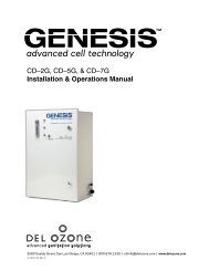
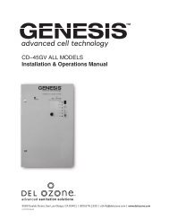
<strong>CD</strong>–<strong>15G</strong> ALL MO<strong>DEL</strong>S<strong>CD</strong>–<strong>25G</strong> ALL MO<strong>DEL</strong>SInstallation & Operations Manual3580 Sueldo Street, San Luis Obispo, CA 93401 | 800.676.1335 | o3info@delozone.com | www.delozone.com4-0558 Rev.F
<strong>Genesis</strong> <strong>CD</strong>–<strong>15G</strong> and <strong>CD</strong>–<strong>25G</strong> Installation & Operations ManualTABLE OF CONTENTSSECTION 1 General Information1A. Description................................................................11B. Specifications............................................................1SECTION 2 Installation2A. Location....................................................................12B. Mounting...................................................................12C. Electrical...................................................................22D. Plumbing...................................................................2SECTION 3 Operation3A. Initial System Start-Up..............................................33B. Normal Operation.....................................................33C. System Shut-Down...................................................3SECTION 4 Maintenance & Service4A. System Electro-Mechanical Overview..................... 34B. PM Schedule........................................................... 74C. Troubleshooting....................................................... 74D. Contact Information................................................. 7SECTION 5 Replacement Parts & Order Info5A. Ordering Information................................................ 7Warranty...................................................................... 8AppendixAppendix "A" (Safety) .................................................... 9Appendix "B" (Troubleshooting Guide) ....................... 15ALL <strong>Genesis</strong> <strong>CD</strong> <strong>Ozone</strong>Generators are NSF listed.IMPORTANT SAFETY INSTRUCTIONSRead and Follow All Instructions.• Read this manual completely before attempting installation.• Risk of Electric Shock. Install the ozone unit and any metallic plumbing associated with the unit at least5 ft from the inside wall of tub or pool.• Risk of Electric Shock. Connect this ozone generator in accordance with the installation instructions.Do not install within an enclosure that would restict ventilation.• (Applicable to cord/plug connected units only) Risk of electric shock. Connect only to a properly grounded,grounding type receptacle.• Do not bury cord.• Warning – To reduce the risk of electric shock, replace damaged cord immediately.• Follow all applicable electrical codes.• Electric shock hazard. Be sure to turn power OFF at power source before any service work is performed.Failure to do so could result in serious injury or death.• Warning – Short term inhalation of high concentrations of ozone and long term inhalation of lowconcentrations of ozone can cause serious harmful physiological effects. DO NOT inhale ozone gasproduced by this device.• For your safety, do not store or use gasoline, chemicals or other flammable liquids or vapors near thisor any other appliance.• A spontaneous and violent ignition may occur if oil, grease or greasy substances come in contact withoxygen under pressure. These substances must be kept away from oxygen regulators, cylinder valvestubing and connections, and all other oxygen equipment.SAVE THESE INSTRUCTIONS!
<strong>Genesis</strong> <strong>CD</strong>–<strong>15G</strong> and <strong>CD</strong>–<strong>25G</strong> Installation & Operations ManualSECTION 1 General Information1A. DescriptionThe <strong>Genesis</strong> Corona Discharge series ozonegenerator described in this manual is designedto provide the benefits of ozonated water in anenvironmentally safe and effective manner. Thehigh quality, specially engineered componentsensure efficient ozone output and reliableperformance.39.2 995The <strong>Genesis</strong> <strong>CD</strong> ozone generator is safe andharmless to your equipment if installed properly.A24.1 61312.3 31124.4 620ADIM "A" = 6 [152] MIN CLEARANCE11.7 297DOOR SWINGR24.5 621SECTION 2 Installation2A. Location<strong>CD</strong>–<strong>15G</strong> amd <strong>CD</strong>–<strong>25G</strong> are designed for eitherfloor or wall mounting in a clean, protected area,either indoors or outdoors. Locate generator outof reach of sprinklers or drainage spouts. Allowsufficient access for maintenance and all tubingand electrical wires. Generators must not beplaced in locations where ambient ozone levelsexceed 0.01 PPM.2B. MountingNOTE: Do not remove compressor packingmaterial until unit has been mounted.2B-1. Wall Mount Option1. Attach two mounting brackets to wall usinganchors appropriate for mounting surface.See Figure 2.2. Using 1/4"-20 bolts (with washers as shown)secure generator to mounts.2B-2. Floor Mount Option1. Use the four 1/4"-20 bolts with washers tosecure feet to bottom of cabinet.2. Stand upright and securely fasten to concreteslab using appropriate anchors and bolts.MOUNTINGBRACKETS (2)4.0 102MIN. CLEARANCE(IF WALL MOUNTED) 4.0 102Figure 11B. Specifications1B-1. For detailed specifications refer to the ozonegenerator specification label located on the insideof the door on the unit.1B-2. Location Requirements*:Mounting: Floor or wall mount in a clean, protectedarea using supplied brackets.Ventilation: Room should provide 6 air changesper hourAmbient Temp.: 40–100˚F (5–38˚C)* Protection from weather elements must be providedfor outdoor installations. Operating outside of therecommended temp. ranges may result in damagenot covered under the manufacturer’s warranty.Figure 2: Wall Mount1
<strong>Genesis</strong> <strong>CD</strong>–<strong>15G</strong> and <strong>CD</strong>–<strong>25G</strong> Installation & Operations Manual2C. ElectricalRefer to the units specification label and localelectrical codes for information on proper electricalconnection.120V ModelsMain power circuit: Unit is supplied with astandard power cord. Plug cord into standard120V grounded, gounding type receptacle only.230V ModelsMain power circuit: 230V models are suppliedwith an IEC 6032 C-14 Type power receptacle.A power cord, having at least a 10AMP rating, witha IEC 60320 C-13 Type plug and a country specificplug is required to power generator.Figure 3: Country Specific Plug(Australia shown for reference only)2D. Plumbing<strong>Ozone</strong> gas is introduced to the circulation lineusing a venturi injector. Suction developed by theventuri allows the generator to operate safely undervacuum. See installation manual for MX-601-XXfor proper venturi installation.2D-1. <strong>Ozone</strong> Gas Line1. Connect ozone tubing to generator outlet fitting.(3/8" stainless steel compression fitting.)2. Connect opposite end of ozone tubing to injectorsuction port. (Suction port fitting: 3/8" stainlesssteel compression fitting.) See Figure 4.NOTE: The ozone gas supply line must bemade of Teflon or stainless steel and have aback flow prevention device (such as a checkvalve) installed between the ozone generatorcabinet and the point of injection to preventwater from backing up into the generatorsystem. An ozone supply check valve isincluded with the MX–601–XX system.Figure 4: Plumbing Schematic - Example of Swimming Pool Application2
<strong>Genesis</strong> <strong>CD</strong>–<strong>15G</strong> and <strong>CD</strong>–<strong>25G</strong> Installation & Operations Manual2D-2. Cooling WaterCooling Water Flow: .1 Gpm (.4 Lpm)Colling water Pressure: 15–40 psi (103–275 kPa)Cooling Water Temp.: 5–90˚F (10–32˚C)1/4" FPT connections are supplied on thegenerator. See Figure 4, 5a, 6a. Be sure thatthe tubing is appropriately matched with the markedinlet and outlet ports. Carefully match and connectto water plumbing as shown in Figure 4. Alternatemethod using connections at injector may be used.SECTION 3 Operation3A. Initial System Start-UpUpon completing all of the generator systemconnections, you are ready to begin start-upprocedures.1. Check electrical fittings.2. Check for proper voltage.3. Turn on circulation pump.4. Check for leaks.5. With the ozone isolation valve closed, adjust theinjector bypass valve and/or filtration sidestreamvalve to flow water through the injector.6. Check cooling water.7. Open the ozone isolation valve.8. Turn main power switch to "ON" position.9. Adjust injector by-pass to attain required vacuum.(Red "Vacuum" light will go out.) Gas flow(as indicated by the flow meter on the door ofthe unit) should correspond with the rating listedfor the specific model on the specification label.3B. Normal OperationWith the power switch on, the system’scompressors and cooling fans will start-up, theoxygen concentrator will begin operating, andthe output solenoid valve will open. With theinjector adjusted to attain the correct gas flow,the ozone generator should be producing ozoneand injecting it into the process line.Both (2) green indicator lights should be lit. Ifan optional ORP Controller is installed, it shouldbe displaying a reading from the sensor probeand will automatically cycle the generator on andoff as needed to maintain water quality. ResidualORP levels will vary per application.However, the system will not start under any ofthe following conditions:1. The system will not start-up if the door is notsecured. A door interlock switch is incorporatedinto the system enclosure.2. If the optional ORP/DO3 controller is installed thesystem will not produce ozone if the measuredlevel is already above the setpoint of the controller.3. The system will not produce ozone if there is notenough vacuum being generated by water flowthrough injector. The red "Vacuum" light will goout when proper vacuum is attained.If you experience complications, see APPENDIX"B", TROUBLESHOOTING GUIDE or call1-800-676-1335 for assistance.3C. System Shut-DownThe <strong>Genesis</strong> Corona Discharge ozone generatoris a specialized water cooled device that must beproperly protected during shut-down/storageperiods.The following sequence of steps must beused for servicing or for storage.1. Toggle the main system power switch to the“OFF” position to shut-down generator.2. Close the ozone isolation valve to prevent waterback flow.3. After the generator has been shut-down, theprocess water circulation pump may be turnedoff.4. If the system is going to be shut-down andstored during freezing weather, it is veryimportant that the cooling water be drained toprotect it from rupture or damage.NOTE: Process water flow must not be shutdownwhen the ozone generator is operating.Doing so may cause water to backflow intothe system and damage the generator cells.SECTION 4 Maintenance & Service4A. System Electro-Mechanical OverviewRefer to Figure 5a and 6a for component locations.4A-1. Indicator Lights1. Main Power: Green light indicates that power isbeing supplied to the ozone generator.2. <strong>Ozone</strong> Power: Green light indicates that poweris being supplied to the high voltage CoronaDischarge circuits and that ozone is beingproduced.3. Vacuum: Red light indicates a low vacuum fault3
<strong>Genesis</strong> <strong>CD</strong>–<strong>15G</strong> and <strong>CD</strong>–<strong>25G</strong> Installation & Operations Manualcondition. (Refer to APPENDIX "B",TROUBLESHOOTING GUIDE.)4. High Coolant Temperature: Red light indicatescell temperature is over 110F - resulting fromloss of cooling water flow. (Refer to APPENDIX"B", TROUBLESHOOTING GUIDE.)5. Water Backflow Detected: Red light indicateswater backflow from injector into generator.(Refer to APPENDIX "B", TROUBLESHOOTINGGUIDE.)4A-2. External Components1. Main Power Switch: Power switch is used forsystem start-up and shut-down. Switch activatesthe control system allowing the generator tostart up.2. Flowmeter: Flowmeter controls and indicatesthe oxygen flow through the system.3. Circuit Breaker: Circuit breaker protects thegenerator from over current conditions. Pushthe breaker button to reset.4A-3. Internal Components1. Variable Output Switch (optional): Adjustshigh voltage power supplied to the ozonegenerator module controlling ozone outputconcentration. Located on the outside of theenclosure door.4A-4. External Devices that Control <strong>Ozone</strong>ProductionThe devices turn ozone production on or offbased on programmed level set points. Referto Figure 5b and 6b for connection details.1. ORP Controller (optional): The ORP controllerreceives a millivolt (mV) signal from the ORPsensor mounted in the process water line. ORP(Oxidation-Reduction Potential) is a measureof the relative oxidation strength of the water.As ozone is added to the water system the ORPlevel will rise. As ozone is used up in the watersystem the ORP level will drop. The ORPcontroller continuously analyzes the sensorsignal, compares it to the setpoint that hasbeen programmed, indicates the ORP level onthe digital display, and relays the signal to theozone generator.2. Dissolved <strong>Ozone</strong> Monitor (optional):Monitoring system designed for the continuousmeasurement of ozone gas in solution. Theoperating range of the system may be selectedby the user from 0-2.00 PPM or from 0-20.00PPM. The basic sensing element used ispolarographic membraned sensor whichmeasures ozone directly.4A-5. External Devices that Control SystemPowerThe devices turn power to the ozone generatoron or off. Examples of such devices would be anambient ozone monitor or flow switch. Refer toFigure 5b and 6b for connection details.4A-6. Internal Components1. <strong>Ozone</strong> Cell Assembly: Cells are made of twoaluminum halves. Enclosed in the aluminumhalves are a ceramic tube, coil type high voltageelectrode and a teflon rod.2. High Voltage Supply(s): Power supplies raiseincoming line voltage and frequency to deliver itto the cells. Each power supply is rated at 100W.3. Air Compressors: Compressors produce andsupply compressed air to oxygen concentrator.4. Oxygen Concentrator: Supplies concentrated,dry, oxygen feed gas to the ozone generator.5. Low Limit Vacuum Switch: If the vacuum in theozone output supply line falls below 1.5 in. Hgthe switch will open causing the system to shutdown.6. Vacuum Regulator: Regulates the oxygenflow into the generator cell based on a vacuumsetpoint (factory set to 3-5 in. Hg). When thesufficient suction is being developed by theinjectors downstream the regulator will allow fullflow to pass. As suction is reduced, flow isrestricted proportionally to maintain the vacuumset point. If suction is lost completely, flow iscut off.7. Water Backflow: The backflow detector senseswater present in ozone tubing in generator. Ifwater is detected, system will close solenoidvalve to prevent additional water backflow fromoccuring. Water in the generator will causesevere damage to the high voltage electrodes.8. Ventilation Fan: Cooling fan operates whenmain power switch is “ON”.9. Air Filter: Filter cleans ventilation air enteringthe enclosure.10. Door Interlock Switch: Interlock switch willshut down entire system if door is opened.Securing the door will bring the system backinto operation.11. Relay Panel: Contains control relays for systeminterlocks, indicator lights and main powercontrol.12. Hour Meter: Indicates total system operatingtime in hours.4
<strong>Genesis</strong> <strong>CD</strong>–<strong>15G</strong> and <strong>CD</strong>–<strong>25G</strong> Installation & Operations ManualFigure 5a: Component Locations (ALL MO<strong>DEL</strong>S EXCEPT –50)Relay PanelRemove jumper if ORP controller or dissolvedozone monitor is used. Connect dry contactleads from controller/monitor or leave openif 5 pin external interface connector is used.Remove jumper and connect dry contact leads ifexternal device is used. (ambient ozone, flow switch,etc.)Figure 5b: Connection Details for External Control Devices (ALL MO<strong>DEL</strong>S EXCEPT –50)5
<strong>Genesis</strong> <strong>CD</strong>–<strong>15G</strong> and <strong>CD</strong>–<strong>25G</strong> Installation & Operations ManualAIR COMPRESSORCOMPRESSORAIR FILTERDOOR SWITCHHOUR METERRELAY PANELON/OFF SWITCHFANSHIGH VOLTAGEPOWER SUPPLIES5 PIN EXTERNALINTERFACECONNECTOROPTIONALVARIABLEOUTPUT SWITCHOXYGENCONCENTRATORVACUUM REGULATOR& SOLENOID VALVEOZONE CELLASSEMBLYINDICATORLIGHTSFLOW METERRECEPTACLEIEC 60320 C-14CIRCUITBREAKERS (2)VACUUM & PRESSURESWITCHESCOOLING WATER OUTOZONE OUTBACK FLOW PREVENTER& SOLENOID VALVECOOLING WATER INAIR INTAKE SCREENS (3)Figure 6a: Component Locations (–50 MO<strong>DEL</strong>S)K3Relay PanelK5K1K2K4Remove jumper if ORP controller or dissolvedozone monitor is used. Connect dry contactleads from controller/monitor or leave openif 5 pin external interface connector is used.Remove jumper and connect dry contact leads ifexternal device is used. (ambient ozone, flow switch,etc.)Figure 6b: Connection Details for External Control Devices (–50 MO<strong>DEL</strong>S)6
<strong>Genesis</strong> <strong>CD</strong>–<strong>15G</strong> and <strong>CD</strong>–<strong>25G</strong> Installation & Operations Manual4B. Preventative Maintenance ScheduleRegular maintenance should be performed to avoiddamage to the system, more costly repairs andto keep the warranty active. For instance, thecompressor should be rebuilt every 8,750 hoursto prevent the reduction in air-pressure and flow.If the compressor is not rebuilt, oxygen concentratorsieve beds will become plugged and unusable,creating more costly problems. If the generatorcells are not cleaned or replaced annually, a lowerozone output will result.DAILY:Check ozone generator for proper operation.- Make sure no red indicator lights are lit.- Make sure flow meter is indicating properair flow.MONTHLY:1. Inspect compressor air filter.- Replace quarterly2. Remove and clean air filter or intake screensSee Figure 7.- Remove filter cover plate to access filter.- Rinse filter in warm, soapy water and blow dry.- Replace filter.- For the <strong>CD</strong>–<strong>15G</strong>V–50 and <strong>CD</strong>–<strong>25G</strong>V–50,remove and clean intake screens.3. Perform general cleaning of cabinet interior.EVERY 8,750 HOURS:1. Rebuild compressor. Kit Avaiable. See Section 5for ordering information.2. Replace/Service Check Valve(s) and SolenoidValves.3. Replace ozone cell O-rings and inspect ozonecells.4C. TroubleshootingSee APPENDIX "B", TROUBLESHOOTING GUIDENOTE: Knowledge of electrical applications isrequired for trouble shooting. Contact a certifiedelectrician if you are unsure of your ability toservice the equipment. If any condition persists,call 1-800-676-1335 for technical assistance.4D. Contact InformationFor Technical assistance:Call: 1-800-676-1335 ext. 293Email: service@delozone.comVisit: www.delozone.comSECTION 5 Replacement Parts &Order Information5A. Ordering informationFor replacement parts call <strong>DEL</strong> at 1-800-676-1335.Be prepared with the following information:• Customer Name• Customer Address• <strong>DEL</strong> Model Number• <strong>DEL</strong> Serial Number• Date Purchased• Proof of PurchaseIntake Screenbottom ofcd cabinetFigure 7: Filter or Intake Screen Removal for Cleaning7DETAIL B
<strong>Genesis</strong> <strong>CD</strong>–<strong>15G</strong> and <strong>CD</strong>–<strong>25G</strong> Installation & Operations Manual<strong>DEL</strong> OZONECOMMERCIAL PRODUCTLIMITED TWO YEAR WARRANTYThe limited warranty set forth below applies to products manufactured by <strong>DEL</strong> OZONE – 3580 Sueldo Street, San LuisObispo, California 93401, and sold by <strong>DEL</strong> OZONE or its authorized dealers. This limited warranty is given only to the firstretail purchaser of such products and is not transferable to any subsequent owners or purchasers of such products.Systems sized 65 grams or greater require factory commissioning and startup to maintain warranty as set forth below.<strong>DEL</strong> OZONE warrants that <strong>DEL</strong> or <strong>DEL</strong> authorized dealers will repair or replace, at <strong>DEL</strong>’s option, any part of suchproducts proven to be defective in materials or workmanship within two (2) years of the date of receipt. Parts are coveredunder the two (2) year warranty when and only when the stated maintenance requirements are met. Contact tanks anddegas valves have a ninety (90) day warranty. Compressor(s) must be maintained per operation and maintenancemanual. Required maintenance includes a compressor rebuild after one (1) year or every 8,760 hours, which ever isreached first. Warranty does not include parts for compressor(s) rebuild kit(s), or other consumable items. See owner’smanual for complete maintenance details. This Warranty specifically excludes any components not manufactured by <strong>DEL</strong>OZONE that are external to the products covered, such as pumps, air compressors, monitors, tanks, or relatedcomponents. <strong>DEL</strong> OZONE will assist with warranty claims for such components purchased through <strong>DEL</strong> OZONE; limitedto the extent of the manufacturer’s standard warranty. ANY REPAIR OR REPLACEMENT WILL BE WARRANTED ONLYFOR THE BALANCE OF THE ORIGINAL TWO (2) YEAR WARRANTY PERIOD.NOTE: USE ONLY <strong>DEL</strong> AUTHORIZED <strong>DEL</strong> REPLACEMENT PARTS. USE OF ANY OTHER PART(S) WILL VOIDTHIS WARRANTY.Any replaced parts must be returned to <strong>DEL</strong> OZONE for warranty evaluation.THIS LIMITED WARRANTY DOES NOT INCLUDE ANY OF THE FOLLOWING:(a)(b)(c)(d)(e)(f)Any labor charges for troubleshooting, removal, or installation of such parts.Any repair or replacement of such parts necessitated by faulty installation, improper maintenance, improperoperation, misuse, abuse, negligence, accident, fire, flood, repair materials, and/or unauthorized accessories.Any such products installed without regard to required local codes and accepted trade practices.Damage to unit caused by water backflow;Any implied warranty of merchantability or implied warranty of fitness for particular purpose, and suchwarranties are hereby disclaimed.<strong>DEL</strong> <strong>Ozone</strong> shall not be liable under any circumstances for loss of use of such product, loss of profits, directdamages, indirect damages, consequential damages, and / or incidental damages.This warranty gives you specific legal rights. You may have other rights which vary from state to state.Extended Warranties and Service Agreements are available. Contact <strong>DEL</strong> for additional details.TO OBTAIN WARRANTY SERVICE:<strong>DEL</strong> OZONE3580 Sueldo, San Luis Obispo, CA 93401Customer Service Number: (800) 676-1335Fax Number: (805) 541-8459E mailservice@delozone.comPROVIDE:1. Project, contact name, mailing address and telephone.2. Installer/Mechanical Contractor.3. Unit Part Number, Serial Number, and date of purchase.4. The date of failure.5. A description of the failure.After this information is provided, <strong>DEL</strong> <strong>Ozone</strong> may release a RETURN GOODS AUTHORIZATION (RGA) NUMBER. After receiving the RGA numberthe part in question must be returned to <strong>DEL</strong> <strong>Ozone</strong>, freight prepaid, with the RGA number clearly marked on the outside of the package. Allpreauthorized defective parts must be returned to <strong>DEL</strong> <strong>Ozone</strong> within thirty (30) days. Under no circumstances may any product be returned to <strong>DEL</strong><strong>Ozone</strong> without prior authorization. Returns without the assigned RGA number on the outside of the package will be refused and shipped back to thesender at their expense. Upon receipt of preauthorized returned goods, <strong>DEL</strong> <strong>Ozone</strong> will repair or replace, at <strong>DEL</strong> <strong>Ozone</strong>’s option, the defective product(s)and return them (freight prepaid for products under warranty). Buyer’s acceptance of the product and use thereof constitutes acceptance of these terms.4-1370-01_Rev.D8
<strong>Genesis</strong> <strong>CD</strong>–<strong>15G</strong> and <strong>CD</strong>–<strong>25G</strong> Installation & Operations ManualAPPENDIX “A”SAFETY9
<strong>Genesis</strong> <strong>CD</strong>–<strong>15G</strong> and <strong>CD</strong>–<strong>25G</strong> Installation & Operations ManualOZONEMaterial Safety Data SheetSECTION I: MATERIAL IDENTIFICATIONIDENTITY: OZONE (Gaseous) ISSUED: February, 1992FORMULA: O 3 REVISED: March, 2009Description (origin/uses): Occurs in atmosphere from UV light action on oxygen at high altitude. Commercially obtained bypassing air between electrodes carrying a high voltage alternating current. Also found as a by-product in welding areas, highvoltage equipment, or UV radiation.<strong>Ozone</strong> is used as an oxidizing agent in air and water disinfection: for bleaching textiles, oils, and waxes; organic synthesis as inprocessing certain perfumes, vanillin, camphor; for mold and bacteria control in cold storage.Cautions: A powerful oxidizing agent, ozone generally exists as a gas and is highly chemically reactive. Inhalation producesvarious degrees of respiratory effects from irritation to pulmonary edema (fluid in lungs) as well as affecting the eyes, blood, andcentral nervous system.Manufacturer/Supplier: On-site generation, equipment available from various suppliers, including:<strong>DEL</strong> <strong>Ozone</strong>Phone: (805) 541-16013580 Sueldo StreetSan Luis Obispo, CA 93401FAX: (805) 541-8459SECTION II: INGREDIENTS AND HAZARDS<strong>Ozone</strong>, CAS No. 10028-15-6: NIOSH RTECS No. RS82250001991 OSHA PELs8-hr TWA: 0.1 ppm vol. (0.2 mg/m 3 )15-min STEL: 0.3 ppm vol (0.6 mg/m 3 )1990 IDLH10 ppm1990 NIOSH RELCeiling: 0.1 ppm vol. (0.2 mg/m 3 )Other Designations:Boiling Point: . . . . . . .Vapor Pressure: . . . . .Vapor Density (AIR = 1):Solubility in Water: . . .1991-1992 ACGIH TLVCeiling: 0.1 ppm (0.2 mg/m 3 )1990 DFG (Germany) MAKTWA: 0.1 ppm (0.2 mg/m 3 )Category 1: Local IrritantPeak Exposure Limit: 0.2 ppm5 min momentary value, 8 per shiftTriatomic oxygen: CAS No. 10028-15-6, NIOSH RTECS No. RS8225000-169° F>1 ATM1.60.49 ml @ 32° F (0° C),3 ppm @ 20 ° CSECTION III: PHYSICAL DATAMelting Point: . . . . . . . .% Volatile by Volume: . .Molecular Weight: . . . . .pH: . . . . . . . . . . . . . . . .Critical Temperature: . .-315.4° F (-193° C)100%48 Grams/MoleNot Listed10.22° F (-12.1° C)Appearance and Odor: Colorless to blue gas (greater than -169° F): characteristic odor often associated with electrical sparks orlightning in concentrations of less than 2 ppm and becomes disagreeable above 1-2 ppm. CAUTION: Olfactory fatigue developsrapidly, so do not use odor as a preventative warning device.Flash Point: . . . . . . . .Extinguishing Media: .SECTION IV: FIRE AND EXPLOSION HAZARD DATANonflammableUse large amounts of water spray or fog to put out fires involving ozone. Use appropriate fire-fightingtechniques to deal with surrounding material.Special Fire Fighting Procedures: Wear a self contained breathing apparatus with full face pieces operated in a pressuredemandor other positive-pressure mode.Unusual Fire/Explosion Hazards: Decomposition of ozone into oxygen gas, (O 2 ), can increase strength of fire.SECTION V: REACTIVITY DATAStability: <strong>Ozone</strong> is not stable. Hazardous polymerization cannot occur.Chemical Incompatibilities: <strong>Ozone</strong> is chemically incompatible with all oxidizable materials, both organic and inorganic.Conditions to Avoid: <strong>Ozone</strong> is unstable at room temperatures and spontaneously decomposes to oxygen gas. Avoid ignitionsources such as heat, sparks, and open flame. Keep away from strong reducing agents and combustible materials such asgrease, oils, and fats.Products of Hazardous Decomposition:<strong>Ozone</strong> spontaneously decomposes to oxygen gas, even at room temperatures.4-0697_ Rev.B10
<strong>Genesis</strong> <strong>CD</strong>–<strong>15G</strong> and <strong>CD</strong>–<strong>25G</strong> Installation & Operations ManualCarcinogenicity:Primary Entry:Target Organs:SECTION VI: HEALTH HAZARD DATA<strong>Ozone</strong> is not listed as a carcinogen by the NTP, IARC, or OSHA.InhalationRespiratory system, eyes, blood.Summary of Risks: There is no true threshold limit and so no exposure (regardless of how small) is theoretically without effectfrom ozone’s strong oxidative ability. <strong>Ozone</strong> passes straight to the smallest bronchioles and alveoli and is not absorbed bymucous membranes along the way. Initial small exposure may reduce cell sensitivity and/or increase mucous thicknessproducing a resistance to low ozone levels. Short exposure to 1-2 ppm concentrations causes headache as well as irritation tothe respiratory tract. but symptoms subside when exposure ends. High concentrations of ozone produce severe irritation of theeyes and respiratory tract. Exposure above the ACGIH/OSHA limits produce nausea, chest pain, coughing, fatigue, reducedvisual acuity, and pulmonary edema. Symptoms of edema from excessive exposure can be delayed one or more hours.Inhalation of >20 ppm for an hour or more (>50 ppm for 1/2 hour) can be fatal.Acute Effects:Chronic Effects:Acute damage from ozone appears to be mainly from its oxidizing effect on contact with tissue.Respiratory disease. Deleterious effects on lungs and acceleration of tumors have been reported.Medical Conditions Generally Aggravated by Long-Term Exposure:History of respiratory or heart disorders.First Aid: Remove from ozone containing air, get prompt medical help*, administer oxygen if necessary.Eye Contact - Gently lift eyelids and flush eyes continuously with flooding amounts of water for 15 minutes or until transported to amedical facility*.Inhalation - Remove exposed person to fresh air, support breathing, administer humidified oxygen as needed, get medical help*.Ingestion - Highly unlikely since ozone is a gas until -169° F,* GET MEDICAL ASSISTANCE = APPROPRIATE IN-PLANT, PARAMEDIC, or COMMUNITY. Get prompt medical assistance forfurther treatment, observation, and support after first aid.SECTION VII: PRECAUTIONS FOR SAFE HANDLING AND USESteps to be Taken in Case of Spill/Leak:1. Discontinue production2. Isolate and vent area3. Immediately notify personnel4. Deny entry5. Follow applicable OSHA regulationsDisposal: Provide ventilation to dilute and disperse small amounts of ozone (below OSHA PELs) to outside atmosphere. Followfederal, state, and local regulations.Handling/Storage Precautions:Respiratory Protection:Eye Protection:Skin Protection:Ventilation:Ensure proper personnel training and establish emergency procedures.SECTION VIII: CONTROL MEASURESHigh Level (>10 ppm) - Self Contained Breathing Apparatus: MISH/NIOSH approved.Low Level (0.3 - 10 ppm) - Canister Type (carbon) respirator may be used.Wear chemical safety goggles if necessary to work in high ozone (>10 ppm).Effects of ozone on skin are minimal to non-existent.Provide general and local exhaust ventilation to dilute & disperse small amounts of ozone into outside atmosphere.SECTION IX: SPECIAL PRECAUTIONS AND COMMENTSStorage Segregation: Prevent ozone from coming into direct physical contact with strong acids or bases or with strongoxidizing/reducing agents.Engineering Controls: Install ventilation systems capable of maintaining ozone to concentrations below the ACGIH/OSHAexposure limits (see sect. II). Install ambient ozone monitor(s) configured to shut down ozone equipment and turn high speedventilation on.4-0697_ Rev.B11
<strong>Genesis</strong> <strong>CD</strong>–<strong>15G</strong> and <strong>CD</strong>–<strong>25G</strong> Installation & Operations ManualPage 1 of 3Material Safety Data SheetThis MSDS complies with OSHA’s Hazardous CommunicationStandard 29 CFR 1910.1200 and OSHA form 174.NFPA 704 DesignationHazard Rating<strong>DEL</strong> <strong>Ozone</strong>3580 Sueldo StreetSan Luis Obispo, CA 93401Product Information 805-541-16014 = Extreme3 = High2 = Moderate1 = Slight0 = InsignificantProduct NameChemical NameAQUEOUS OZONE SOLUTIONDISSOLVED OZONE GAS IN WATER 0 TO 2 PPMProduct DescriptionD.O.T. ShippingClassificationAQUEOUS SOLUTION OF OZONE DISSOLVED IN POTABLE WATERNON REGULATEDI PHYSICAL DATABoiling Point 212 F Freezing Point 32 FSpecific Gravity 1.0 Solubility in Water COMPLETEEvaporation Rate APPROX 1 Physical Form LIQUIDAppearance & OdorCOLORLESS (CLEAR) WATER WITH FRESH, ASEPTIC ODORII HAZARDOUS INGREDIENTSMATERIAL HAZARD CAS # % BY WT ACGIH TLV OSHA PELNoneIII FIRE AND EXPLOSION HAZARD DATAFlash Point NA Method NA Auto Ign. Temp. NAFlammable Limits inAirExtinguishing MediaUnusual Fire &Explosion HazardsSpecial Fire FightingProceduresNON APPLICABLE Lower NA Upper NANON APPLICABLENONENONE4-1444-01_Rev.B12
<strong>Genesis</strong> <strong>CD</strong>–<strong>15G</strong> and <strong>CD</strong>–<strong>25G</strong> Installation & Operations ManualPage 2 of 3Material Safety Data Sheet Cont.Product NameAQUEOUS OZONE SOLUTIONIV HEALTH HAZARD DATAThreshold Limit ValueNOT DETERMINEDRoute of Exposure Inhalation Ingestion Skin Eye Not HazardousEye Contact HazardIngestion HazardInhalation HazardSkin Contact HazardSkin Absorption HazardEffects of AcuteExposureEffects of ChronicExposureExposure may cause mild eye irritation, but is not expected.Not HazardousInhalation is not likely to be a primary route of exposure but could become irritating ifaerosols are exposed to individual for extended period of time.No skin irritation is expected from short term exposure.No published data indicates this product is absorbed through the skin.Mild skin or eye irritation.Repeated exposure of the skin to concentrated product should be avoided to preventirritation and drying of the skin.V EMERGENCY AND FIRST AID PROCEDURESEye ContactSkin ContactInhalationIf exposure to water containing aqueous solution of ozone causes irritation to eyes, flush eyes withplenty of clean, ozone free, running water for at least 15 minutes, lifting the upper and lower lidsoccasionally. Remove contact lenses if worn. Seek medical attention if irritation persists.Not likely to become irritated unless repeatedly exposed to large volumes of material. If irritationdevelops, rinse affected area with ozone free potable water. If irritation continues seek medicaladvice.Inhalation of mists could lead to irritation of lungs. If symptoms develop, move individual away fromexposure and into fresh air. If symptoms persist, seek medical attention.IngestionNAVI REACTIVITY DATAIncompatibility(Materials to Avoid)Conditionsto AvoidHazardousDecompositionNatural rubber (may degrade, or “dry”, rubber components over extended periods of exposure)NONE KNOWNNONEStability STABLE UNSTABLE Hazardous Polymerization MAY OCCUR WILL NOT OCCUR4-1444-01_Rev.B13
<strong>Genesis</strong> <strong>CD</strong>–<strong>15G</strong> and <strong>CD</strong>–<strong>25G</strong> Installation & Operations ManualPage 3 of 3Material Safety Data Sheet Cont.Product NameAQUEOUS OZONE SOLUTIONVII SPILL OR LEAK PROCEDURESSteps To Be TakenIf Material Is ReleasedOr SpilledWaste DisposalMethodNONEDISPOSE OF THE SAME AS POTABLE RINSE WATERVIII SPECIAL PROTECTIVE INFORMATIONRespiratory Protection(Specify Type)NOT REQUIRED FOR NORMAL USE OF THIS PRODUCTVentilationLocalExhaustMechanical(general)PREFERABLE Special NAOK Other NAProtective GlovesEye ProtectionOther ProtectiveEquipmentNOT REQUIREDNOT REQUIREDNOT REQUIREDIX SPECIAL PRECAUTIONSPrecautionaryLabelingCertified testing of <strong>DEL</strong> <strong>Ozone</strong> systems by NSF (National Sanitation Foundation) has shown thatunder normal conditions of use, aqueous solutions containing low levels of ozone gas dissolved inpotable water do not present a safety hazard when contact to the individual is incidental. Whenused in a room with normal ventilation, levels of ozone gas being released into the air have beenshown by NSF to be well below the periodic exposure levels established by OSHA for workersafety through the use of <strong>DEL</strong>’s ozone management technology.Precautions To BeTaken In HandlingAqueous solutions of ozone in potable water should not be sprayed as an aerosol (i.e. >20psi) toavoid releasing higher levels of ozone gas into the work area. The decay rate of ozone gas is afunction of temperature and exposure to organic material. Certified testing has shown that whenozone gas has been properly dissolved in ambient temperature (or colder (33 – 70 °F)) potablewater at a level not exceeding 2 mg/l (ppm) using <strong>DEL</strong>’s ozone management technology, the rateat which ozone is released from the water as ozone gas is below the PEL established for gaseousozone.Rev. Date 03/26/09This material safety data sheet is provided as an information resource only. It should not be taken as a warranty or representation for which the preparerassumes legal responsibility. While we believe the information contained herein is accurate and compiled from sources believed to be reliable, it is theresponsibility of the user to investigate and verify its validity. The buyer assumes all responsibility of using and handling the product in accordance withapplicable federal, state, and local regulations.4-1444-01_Rev.B14
<strong>Genesis</strong> <strong>CD</strong>–<strong>15G</strong> and <strong>CD</strong>–<strong>25G</strong> Installation & Operations ManualAPPENDIX “B”TROUBLESHOOTING GUIDE15
<strong>Genesis</strong> <strong>CD</strong>–<strong>15G</strong> and <strong>CD</strong>–<strong>25G</strong> Installation & Operations ManualTROUBLESHOOTING GUIDEFOR <strong>DEL</strong> OZONE <strong>CD</strong>-<strong>15G</strong> & <strong>25G</strong> SERIESOZONE GENERATORSThis document is a guide to help troubleshoot problems that might arise in operation of the <strong>DEL</strong> <strong>Ozone</strong><strong>CD</strong>-<strong>15G</strong> & <strong>25G</strong> Series ozone generators. It contains three main sections that when used togetherprovide a basic overview of the ozone generator layout, troubleshooting table for common problems, andelectrical, pneumatic, and hydraulic order diagrams. If you still need help, call our Commercial ServiceDepartment at 1-800-676-1335.Note: Always disconnect the ozone generator from the power source before attempting service or repair.Image 1: <strong>Ozone</strong> Generator Component Locations (<strong>CD</strong>-<strong>25G</strong>V model shown)12152212316321319171412842931252710309221824732685611201. 5-Pin connector (not shown) 12. Door switch 23. Power switch2. 12VDC power supply (optional) 13. Flowmeter 24. Pressure relief valve3. Backflow prevention device (BFPD) 14. Fuse 25. Pressure switch4. Brass orifice 15. Hourmeter 26. S.S. check valve5. Cabinet fan 16. Indicator lights 27. Terminal block 1 (TB1)6. Cabinet filter (not shown) 17. Oxygen concentrator 28. Terminal block 4 (TB4)7. Circuit breaker 18. Oxygen solenoid valve 29. Thermal switch (not shown)8. Compressor 19. <strong>Ozone</strong> cells 30. Vacuum regulator9. Compressor air filter 20. <strong>Ozone</strong> output fitting 31. Vacuum switch10. Cooling block assembly 21. <strong>Ozone</strong> power supplies11. Cooling water in & out fittings 22. <strong>Ozone</strong> solenoid valve32. Variable ozone output control(optional)TSG <strong>CD</strong>-<strong>15G</strong> & <strong>25G</strong> 1 of 4 4-1529-01_Rev.A16
<strong>Genesis</strong> <strong>CD</strong>–<strong>15G</strong> and <strong>CD</strong>–<strong>25G</strong> Installation & Operations ManualTable 1: Troubleshooting(for best results follow the table order)Problem (Indication) Possible Cause Corrective Action1. Unit does not starta. Unit is not supplied power(main power light is off and nosound is coming from the unit)2. Unit is in vacuum fault(vacuum light is on)3. Unit is in high temperature fault(high coolant temperature light ison)4. Unit is in backflow fault(water backflow detected light is on)5. Unit does not flow gas(flowmeter at bottom of scale)6. Unit ozone production does notstart(both ozone power and vacuumlights are off)7. Unit does not provide effectivesanitation(both main power and ozone powerlights are on)Connect unit to power sourceTurn power source breaker onReset power source G.F.C.I.Verify power source voltage iswithin unit specificationb. Unit door switch is open Close unit doorc. Unit power switch is in off position Turn power switch ond. Unit circuit breaker is tripped Reset circuit breakera. Inadequate vacuum is supplied tounitConnect unit to vacuum source(injector)Adjust injector to provide morevacuumFix leak or obstruction in plumbingbetween injector and unitb. Unit S.S. check valve has failed Clean or replace S.S. check valvec. Unit vacuum switch has failed Replace vacuum switchd. Unit vacuum regulator requiresadjustment or has faileda. Unit thermal switch has trippedCall service department forassistanceReduce supplied cooling watertemperature and/or increase flowrateObstruction or scaling in coolingblock assembly (clean or replace)b. Unit thermal switch has failed Replace thermal switcha. Water has returned from injectionpoint and triggered unit back flowfloat switchDisconnect ozone line betweeninjector and unit at ozone outputfitting, drain BFPD vessel, andreplace SS check valvea. Unit flowmeter valve is closed Adjust flowmeter valve openb. Unit jumper(s) at TB1 are removed(optional system control hookup, e.g.flow switch and/or ambient O3)c. Unit fuse is blown Replace fused. Unit pressure switch is not activeRe-install jumper(s) and/or verifysystem control(s) are operationalVerify unit plumbing betweenoxygen concentrator and pressureswitch is securely connectedReplace compressor air filterRebuild compressorReplace oxygen concentratore. Unit orifice is plugged Clean or replace orificef. Unit solenoid valve(s) has failed Clean or replace solenoid valve(s)g. Unit flowmeter ball is stuck onbottom of sight tubeh. Unit vacuum regulator requiresadjustment or has faileda. Unit jumper at TB4 is removed(optional external ozone controlhookup, e.g. ORP or dissolved O3,directly wired or through 5-Pin)a. Unit variable ozone output controlsetting is too low (optional feature)b. Leak in plumbing that dilutesapplied ozone dosec. Low gas flow and/or low oxygenconcentrationRepair or replace flowmeterCall service department forassistanceRe-install jumper and/or verifyexternal ozone control isoperationalIf so equipped, increase ozoneoutput settingFix leak in plumbing (inside unitand/or between unit and injector)Replace unit compressor air filterClean or replace unit orificeClean or replace unit check valveRebuild unit compressorReplace unit oxygen concentratord. Unit ozone cell has reached Replace ozone cellservice life or failede. Unit ozone power supply has failed Replace power supplyTSG <strong>CD</strong>-<strong>15G</strong> & <strong>25G</strong> 2 of 4 4-1529-01_Rev.A17
<strong>Genesis</strong> <strong>CD</strong>–<strong>15G</strong> and <strong>CD</strong>–<strong>25G</strong> Installation & Operations ManualTSG <strong>CD</strong>-<strong>15G</strong> & <strong>25G</strong> 3 of 4 4-1529-01_Rev.A18
<strong>Genesis</strong> <strong>CD</strong>–<strong>15G</strong> and <strong>CD</strong>–<strong>25G</strong> Installation & Operations ManualTSG <strong>CD</strong>-<strong>15G</strong> & <strong>25G</strong> 4 of 4 4-1529-01_Rev.A19
3580 Sueldo Street, San Luis Obispo, CA 93401 | 800.676.1335 | o3info@delozone.com | www.delozone.comEPA Estab. No. 071472-CA-001