Defi-Link Display Manual
Defi-Link Display Manual
Defi-Link Display Manual

You also want an ePaper? Increase the reach of your titles
YUMPU automatically turns print PDFs into web optimized ePapers that Google loves.
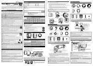
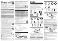
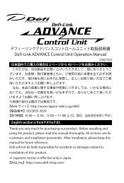
Operation (for the customer)1. Set Up Mode (Screen for setting units and display data parameters.)Confirmationl Be sure to make preparatory settings. The unit will not operate properly without settings being made.When changing the factory settings shown below, pressing the SET UP button after the Opening Mode hascompleted will bring up the setting mode for speed units.ItemSetting Range1 Speed Unitskm/h, MPH2 Pressure/Temperature Units kPa/C, PSI/F3 Speed Pulse2, 4, 8, 16, FREE4 Special <strong>Display</strong>ON, OFF5 Warm-Up20 to 120C, 68 to 248F6 Gauge <strong>Display</strong>Single, Dual7 Tachometer Warning 11000 to 11000 RPMTachometer Warning 2Warning 1 to 11000 RPM<strong>Display</strong> Unitskm/h or MPHkPa/C or PSI/F——C or F—RPMRPMFactory Settingkm/hkPa/C4 pulseON40CSingle7000 RPM8000 RPM3. Gauge Mode(This screen displays actual vehicle data and speed data for metersconnected to <strong>Defi</strong>-<strong>Link</strong> Control Unit II or <strong>Defi</strong>-<strong>Link</strong> Control Unit.)* Does not display Turbo Meter data or Tachometer data.O. TEMP : Oil Temperature Meter W. TEMP : Water Temperature MeterOIL P. : Oil Pressure Meter FUEL P. : Fuel Pressure MeterEXT. T. : Exhaust Temperature MeterPress ENTER to select and adjust the displayed meter.With the ignition on, a “ ” will be displayed for meters with connected sensors.A “/” will be displayed for meters without connected sensors, and selection/adjustmentwill be unavailable.1 Single Gauge ModeEach time the MODE SELECT button is pressed, the displayed meter will change. Press ENTER to set the meter for display.O. TEMP fi W. TEMP fi OIL P. fi FUEL P. fi EXT. T.9. Self-Diagnosis Function(This screen displays serial errors, opens and shorts for each sensor of metersconnected to <strong>Defi</strong>-<strong>Link</strong> Control Unit II or <strong>Defi</strong>-<strong>Link</strong> Control Unit when ignition ison. If an error message is displayed, check the item and take appropriateaction.)1 Serial Error FunctionThis function notifies of communications that have been interrupted between the meter and the Control Unit.2 Disconnection (Open) Check FunctionThis function notifies that a wire disruption, disconnection or improper wiring connection has occurred at the sensoror in the sensor wire.3 Short Circuit Check FunctionThis function notifies that a short circuit has occurred somewhere at the sensor or in the sensor wire.* In Set Up Mode, the item to be set changes each time the ENTER button is pressed. When adjustment of a particularsetting is not needed, press the ENTER button to skip that item.1 Speed Units Æ 2 Pressure Units Æ 3 Speed Pulse Æ 4 Special <strong>Display</strong> Æ 5 Warm-Up Æ 6 Gauge <strong>Display</strong>1 Setting Speed UnitsUse the MODE SELECT button to select Speed Units,then press ENTER to set the desired units.km/h € MPH7 Tachometer Warning 2 ¨ 7 Tachometer Warning 12 Setting Pressure/Temperature UnitsUse the MODE SELECT button to select units for the oil pressure/fuel pressure/oil temperature/water temperature gauges, then press ENTER to set the desired units.kPa/C € PSI/F3 Setting Speed PulseUse the MODE SELECT button to select the speed pulse number, then press ENTERto set the selection.4 fi 8 fi 16 (pulse) fi 2 fi FREE (pulse free)Speed Pulse Number:Pulse Free Setting:Press and holdto change unitsto set the unitsThe speed pulse number differs by model of vehicle.Consult your local car dealer if you are notcertain of the speed pulse number for your vehicle.For vehicles having a speed pulse outside 2, 4, 8, 16 pulse, the speed pulse can be set byswitching to the “Free” screen and then by pressing and holding the ENTER button while thevehicle is moving at 60 km/h or 40 MPH. After 2 seconds of holding the button, the screen willchange and the speed pulse will be set.NormalNormalWith Warning generatedWarning LED2 Dual Gauge ModeEach time the MODE SELECT button is pressed, the displayed meter will change. The upper display is set first, then thelower display. Press ENTER to set the meter for display.O. TEMP fi W. TEMP fi OIL P. fi FUEL P. fi EXT. T. fi SPEED* For O. TEMP, W. TEMP and EXT T. warnings, if the set warning value is exceeded for the displayed meter, the WarningLED will light and the corresponding display value will have reverse lighting.For OIL P. and FUEL P. warnings, if actual value drops below the set warning value, the Warning LED will light and thecorresponding display value will have reverse lighting.Warning LEDWith Warning generated* The upper display has priority when REC, PLAY or PEAK is displayed.4. Speed Mode (This screen displays the vehicle speed.)Pressing the MODE SELECT button while in Gauge Mode will bring up the Speed Mode.Along with display of current vehicle speed, the maximum speed is always monitoredand recorded.Operation (for the customer)2 When connected to <strong>Defi</strong>-<strong>Link</strong> Control Unit.• REC (Recording)Care must be used in operation because <strong>Defi</strong>-<strong>Link</strong> Control Unit operation differs from <strong>Defi</strong>-<strong>Link</strong> <strong>Display</strong>; <strong>Defi</strong>-<strong>Link</strong><strong>Display</strong> determines if it should record/play according to vehicle’s running/stopped condition.Button to PressREAL ModeREC/PLAY buttonPEAK ModeREC/PLAY buttonVehicle’sConditionRunningStoppedRunningStoppedAfter 40 secondsSensor Data Connectedto Control UnitRecordRecordPlayPlaySpeed Data <strong>Display</strong>ed on<strong>Defi</strong>-<strong>Link</strong> <strong>Display</strong>RecordPlayRecordPlay(Record)(Play)Pressing the Control Unit REC/PLAY button in either Gauge Mode, Speed Mode or Triple Warning Mode will startrecording of all data for meters connected to Control Unit and speed data for a maximum of 40 seconds. When 40seconds elapses, the unit will return to the mode used before recording started.To stop recording before the 40 second maximum elapses, press the REC/PLAY button again, and the unit will returnto the mode used before recording started.Speed can be recorded during vehicle running by pressing the REC/PLAY button.* Recording of speed data will be interrupted if wiring disconnection or short circuit occurs during recording.* The unit cannot record while the vehicle is stopped even if the REC/PLAY button is pressed.10. Opening Mode (This screen appears when the ignition is turned on.)Factory setting is for switch to Warm-Up Mode after Opening Mode is complete.OpeningComplete11. Ending Mode (This screen appears when the ignition is turned off.)When connected to Meter Output 2 of Control Unit II, display of the Ending Mode screen isabout 2 seconds longer than when connected to Meter Output 1 of Control Unit II or whenconnected to Control Unit.Warm-Up Setting* If the speed units are changed while using Pulse Free, it is necessary to repeat the pulse freesetting steps.4 Setting Special <strong>Display</strong>Use the MODE SELECT button to select the special display setting, then press ENTERto set the selection.On € Off5 Setting Warm-Up (only available when water temperature sensor is connected)Use the MODE SELECT button to select On or Off, then press ENTER to set the selection.On € Offused toselect On selectionused tosetTemperature Settingpressed once raises value by 1Cpressed and held raises value by 5Cused to set value* When On is selected, each time the MODE SELECT button is pressed, the temperature value setting will increase by 1C andeach time the button is pressed and held, the value will increase by 5C. When the desired temperature value is reached, it isset by pressing the ENTER button.5. Triple Warning Mode(This screen displays a warning when the Tachometer exceeds the engine RPM setwarning value.)Pressing the MODE SELECT button while in Speed Mode will bring up the Triple Warning Mode when the RPM signal wire isconnected to <strong>Defi</strong>-<strong>Link</strong> Control Unit II or <strong>Defi</strong>-<strong>Link</strong> Control Unit.* This mode is not available when connected to <strong>Defi</strong>-<strong>Link</strong> Meter BF.No WarningUnder 9000RPMWarning 1Over 9000 RPMWarning 2Over 10000 RPMWarning 3When <strong>Defi</strong>-<strong>Link</strong> Indicatoris connected, the indicatorflashes being interlockedwith the Warning LED.Warning LEDThe Warning LED lights up when the Tachometer exceeds the warning valueset up by <strong>Defi</strong>-<strong>Link</strong> Control Unit II or <strong>Defi</strong>-<strong>Link</strong> Control Unit.• PLAYAfter recording, pressing the Control Unit REC/PLAY button when PEAK values are being displayed will start playingof all recorded meter data or speed data for a maximum of 40 seconds. When playing is completed, or when theREC/PLAY button is pressed again, the unit will return to the mode used before playing started.Speed can be played by pressing the REC/PLAY button while in PEAK Mode when the vehicle is stopped. If PAUSE ispressed during speed playback, the unit will return to Real Mode.* Recording of speed data will be interrupted if wiring disconnection or short circuit occurred during recording.* The unit cannot play while the vehicle is running even if the REC/PLAY button is pressed.After 40 seconds* If PAUSE is pressed during playback, the time counterdisplay will disappear.• PEAK <strong>Display</strong>Pressing the Control Unit PEAK/RESET button in either Gauge Mode, Speed Mode or Triple Warning Mode willdisplay recorded peak values from all meter data or speed data.Pressing the PEAK/RESET button again will return the unit to the mode used before peak display started.Pressing the Control Unit PEAK/RESET button for 2 seconds while a peak value is displayed will reset the peak value.Optional Parts (for customer)l <strong>Defi</strong>-<strong>Link</strong> Indicator Model number DF01801The indicator flashes red when a meter being displayed on the <strong>Defi</strong>-<strong>Link</strong> <strong>Display</strong> reaches the set warning value.[Indicator Installation Method (for installation personnel)]• When used as an indicator for a connected meter.1. Attach the supplied double-sided tape to the bottom of the indicator body.(Attach 2 layers of double-sided tape for ø4 1/8" (80 mm) orø4 1/2" (115 mm) size meters.)2. Connect the supplied wire.3. Attach the Indicator to the meter or the instrument panel.Double-sidedtapewire6 Setting Gauge <strong>Display</strong>Use the MODE SELECT button to select display data format, then press ENTER to set the selection.Single Gauge € Dual Gaugeused toselectused tosetGauge SettingSingleDual7 Setting Tachometer Warning 1Setting Tachometer Warning 2Use the MODE SELECT button to select warning value, then press ENTER to set the value.Each time the MODE SELECT button is pressed, the value will increase by 100 RPM.1000 fi 1100 fi . . . fi 10900 fi 11000 RPMEach time the MODE SELECT button is pressed and held, the value will increase by 500 RPM.1000 fi 1500 fi . . . fi 10500 fi 11000 RPMTA Triple Warning 1* Only when TA signalis connectedWARN. 1 Lightedpressed once raises value by 100 RPMpressed and held raises value by 500 RPMused to set value. Then WARN. 2 will light.* WARN. 1 setting range:1000 to 11000 RPM* WARN. 1 factory setting:7000 RPMTA Triple Warning 2pressed once raises value by 100 RPMpressed and held raises value by 500 RPMused to set value. Then WARN. 1 will light.* WARN. 2 setting range:WARN.1 WARN. 2 11000 RPM2. Warning Setup Mode(This screen allows setting of warnings for meters connected to<strong>Defi</strong>-<strong>Link</strong> Control Unit II or <strong>Defi</strong>-<strong>Link</strong> Control Unit.)Item1 Turbo Meter2 Exhaust Temp. Meter3 Oil Press. Meter4 Fuel Press. Meter5 Oil Temp. Meter6 Water Temp. Meter7 TachometerSetting Range-100 to 200 kPa or -14.5 to 29.0 PSI200 to 1100C or 390 to 2010F0 to 1000 kPa or 0 to 145 PSI0 to 600 kPa or 0 to 87 PSI50 to 150C or 122 to 302F20 to 120C or 68 to 248F0 to 11000 RPM<strong>Display</strong> UnitskPa or PSIC or FkPa or PSIkPa or PSIC or FC or FRPM* Each time the WARN SET button of <strong>Defi</strong>-<strong>Link</strong> Control Unit II or the SELECT button of <strong>Defi</strong>-<strong>Link</strong> Control Unit ispressed, the meter available for setting will change in the Warning Setup Mode.The value of the setting is adjusted by pressing the UP button or DOWN button of<strong>Defi</strong>-<strong>Link</strong> Control Unit II or <strong>Defi</strong>-<strong>Link</strong> Control Unit.* The resolution of the UP button or DOWN button is adjusted to the analog meter.Because of the difference in step values, the <strong>Display</strong> value changes differently ineach meter.Pressing and holding the button will accelerate the adjustment rate for easier use.1 Turbo Meter Æ 2 Exhaust Temp. Meter Æ 3 Oil Press. Meter Æ 4 Fuel Press. Meter≠Ø7 Tachometer ¨ 6 Water Temp. Meter ¨ 5 Oil Temp. MeteTURBO6. REPLAY <strong>Display</strong>, PEAK <strong>Display</strong>(This screen records vehicle data for meters connected to <strong>Defi</strong>-<strong>Link</strong> Control Unit IIor <strong>Defi</strong>-<strong>Link</strong> Control Unit or it replays the recorded data or displays data peaks.)* Does not display data for Turbo Meter or Tachometer.1 When connected to <strong>Defi</strong>-<strong>Link</strong> Control Unit II.Care must be used in operation because <strong>Defi</strong>-<strong>Link</strong> Control Unit II operation differs from <strong>Defi</strong>-<strong>Link</strong> <strong>Display</strong>; <strong>Defi</strong>-<strong>Link</strong><strong>Display</strong> determines if it should record/play according to vehicle’s running/stopped condition.Button to PressREC buttonPLAY buttonPeakVehicle’sConditionRunningStoppedRunningStoppedAfter 3 minutesAfter 3 minutesSensor Data Connected toControl Unit IIRecordRecordPlayPlayPeak ResetSpeed Data <strong>Display</strong>ed on<strong>Defi</strong>-<strong>Link</strong> <strong>Display</strong>RecordPlayRecordPlay(Record)• REC (Recording)Pressing the Control Unit II REC button in either Gauge Mode, Speed Mode or Triple Warning Mode will startrecording of all data for meters connected to Control Unit II and speed data for a maximum of 3 minutes. When 3minutes elapses, the unit will return to the mode used before recording started.To stop recording before the 3 minute maximum elapses, press the REC button again, and the unit will return to themode used before recording started.Speed can be recorded during vehicle running by pressing the REC button.• PLAYPressing the Control Unit II PLAY button in either Gauge Mode, Speed Mode or Triple Warning Mode will start playingof all recorded meter data or speed data for a maximum of 3 minutes. When playing is completed, or when the PLAYbutton is pressed again, the unit will return to the mode used before playing started.* If PAUSE is pressed during playback, the time counter display will disappear.Speed can be played by pressing the PLAY button when the vehicle is stopped. If PAUSE is pressed during speedplayback, the unit will return to Real Mode.• PEAK <strong>Display</strong>Pressing the Control Unit II PEAK button in either Gauge Mode, Speed Mode or Triple Warning Mode will displayrecorded peak values from all meter data or speed data.Pressing the PEAK button again will return the unit to the mode used before peak display started.Pressing the UP button of Control Unit II while a peak value is displayed will reset the peak value.(Play)PeakWarning LEDSteady FlashDuring Warm-UpWarm-Up CompletedPeak Reset7. Special <strong>Display</strong> Mode(This screen is displayed when speed is 0 Km/h or 0 MPH for more than 10 seconds.)* Turbo Meter and Tachometer are not displayed.When Special <strong>Display</strong> is turned on in Set Up Mode, the peak values for meters having connected sensors aredisplayed from the time ignition is on while in Gauge Mode or Speed Mode.When Special <strong>Display</strong> is turned off in Set Up Mode, the digital display disappears and the Warning LED flashes at asteady interval.* If the Warning LED is lighted while in Gauge Mode, the Special <strong>Display</strong> Mode cannot beactivated.8. Warm-Up Mode (This screen monitors water temperature until it reaches a set value.)When Warm-Up is turned on in Set Up Mode and the water temperature sensor is connected to Control Unit II orControl Unit, the Warm-Up Mode activates after Opening Mode is completed. The “Warm-up” notice and currentwater temperature are displayed until the temperature reaches the set value.When the temperature reaches the set value, the warm-up completed “Ready” notice is displayed for 5 seconds andthe unit returns to the display mode used before the ignition was turned off (Speed Mode, Gauge Mode or TripleWarning Mode). Factory setting is Gauge Mode.Water temperature of 20C (68F) or below is displayed as “ - - -”.If the MODE SELECT button or SET UP button is pressed before water temperature reaches the set value, the unit willswitch to the other mode (except for Warning Setup Mode or Set Up Mode) and a “C” symbol will appear in theupper left corner of the screen until the temperature reaches the set value.,<strong>Display</strong>ing Oil Press./Water Temp.* REC, PLAY and PEAK display cannot be used duringWarm-Up Mode.<strong>Display</strong>ing Speed* REC, PLAY and PEAK display can be used while the “C” symbol is displayed.l <strong>Defi</strong>-<strong>Link</strong> Sensor SetSensor sets include the meter sensor and sensor wire for connection to <strong>Defi</strong>-<strong>Link</strong> Control Unit II or <strong>Defi</strong>-<strong>Link</strong> ControlUnit.If one of the following sensor sets is connected to <strong>Defi</strong>-<strong>Link</strong> Control Unit II or <strong>Defi</strong>-<strong>Link</strong> Control Unit, <strong>Defi</strong>-<strong>Link</strong> <strong>Display</strong>can be used for displaying values even without a meter.Item<strong>Defi</strong>-<strong>Link</strong> OIL PRESS. Sensor Set<strong>Defi</strong>-<strong>Link</strong> FUEL PRESS. Sensor Set<strong>Defi</strong>-<strong>Link</strong> OIL TEMP. Sensor Set<strong>Defi</strong>-<strong>Link</strong> WATER TEMP. Sensor Set<strong>Defi</strong>-<strong>Link</strong> EXHAUST TEMP. Sensor SetModel NumberPDF00713SSPDF00806SSPDF00908SSPDF01006SSPDF01114SS02.9-0.3k