Multi-agent Design of a Traffic-Flow Control System
Multi-agent Design of a Traffic-Flow Control System
Multi-agent Design of a Traffic-Flow Control System

Create successful ePaper yourself
Turn your PDF publications into a flip-book with our unique Google optimized e-Paper software.
<strong>Multi</strong>-<strong>agent</strong> <strong>Design</strong> <strong>of</strong> a<strong>Traffic</strong>-<strong>Flow</strong> <strong>Control</strong> <strong>System</strong>A Project in Collaboration with AAII Tihomir GabrićNicholas HowdenEmma NorlingGil Tidhar yLiz SonenbergTechnical Report 94/24Department <strong>of</strong> Computer ScienceThe University <strong>of</strong> MelbourneParkville, Victoria 3052AUSTRALIAAbstractThis technical report outlines a multi-<strong>agent</strong> oriented approach to improving traffic flowin city streets. The work was undertaken as a summer project between December1993 and February 1994. It was designed to be implemented using the Distributed<strong>Multi</strong>-Agent Reasoning <strong>System</strong> (dMARS) developed at the Australian ArtificialIntelligence Institute (AAII). The primary intention <strong>of</strong> this project was to test andevaluate the paradigm and its current implementation. This report describes thebackground and design <strong>of</strong> the traffic-flow control system. This system consists <strong>of</strong> twocommunicating sub-systems: the simulator, which simulates traffic flowing around asystem <strong>of</strong> roads and intersections; and the controller, which watches over the flow <strong>of</strong>traffic and makes decisions about traffic-light state timings.The Australian Artificial Intelligence Institute.yWith AAII.
Contents1 Introduction 32 <strong>Traffic</strong>-<strong>Flow</strong> <strong>Control</strong>: Problem Definition 42.1 Introduction : : : : : : : : : : : : : : : : : : : : : : : : : : : : : : : : : : 42.2 <strong>Traffic</strong> : : : : : : : : : : : : : : : : : : : : : : : : : : : : : : : : : : : : : 42.2.1 Number <strong>of</strong> Vehicles : : : : : : : : : : : : : : : : : : : : : : : : : : 42.2.2 Density <strong>of</strong> <strong>Traffic</strong> : : : : : : : : : : : : : : : : : : : : : : : : : : : 42.2.3 Speed <strong>of</strong> <strong>Traffic</strong> : : : : : : : : : : : : : : : : : : : : : : : : : : : : 42.3 Roads : : : : : : : : : : : : : : : : : : : : : : : : : : : : : : : : : : : : : 52.3.1 Priorities : : : : : : : : : : : : : : : : : : : : : : : : : : : : : : : : 52.3.2 <strong>Traffic</strong> Capacities : : : : : : : : : : : : : : : : : : : : : : : : : : : 52.3.3 <strong>Traffic</strong> Speeds : : : : : : : : : : : : : : : : : : : : : : : : : : : : : 52.4 Action Areas : : : : : : : : : : : : : : : : : : : : : : : : : : : : : : : : : : 52.4.1 <strong>Traffic</strong> Lights : : : : : : : : : : : : : : : : : : : : : : : : : : : : : 52.4.2 Direction <strong>of</strong> Lanes : : : : : : : : : : : : : : : : : : : : : : : : : : : 62.4.3 Speed Limits : : : : : : : : : : : : : : : : : : : : : : : : : : : : : : 62.5 Area to be Modeled : : : : : : : : : : : : : : : : : : : : : : : : : : : : : : 62.6 Other Considerations : : : : : : : : : : : : : : : : : : : : : : : : : : : : : : 63 <strong>Design</strong> <strong>of</strong> the <strong>Traffic</strong>-<strong>Flow</strong> <strong>Control</strong> <strong>System</strong> 83.1 Introduction : : : : : : : : : : : : : : : : : : : : : : : : : : : : : : : : : : 83.2 Outline <strong>of</strong> <strong>Design</strong> : : : : : : : : : : : : : : : : : : : : : : : : : : : : : : : 83.3 Agents : : : : : : : : : : : : : : : : : : : : : : : : : : : : : : : : : : : : : 83.3.1 Street Agent : : : : : : : : : : : : : : : : : : : : : : : : : : : : : : 93.3.2 Intersection Agent : : : : : : : : : : : : : : : : : : : : : : : : : : : 113.4 Future Expansions : : : : : : : : : : : : : : : : : : : : : : : : : : : : : : : 143.4.1 Global Strategies : : : : : : : : : : : : : : : : : : : : : : : : : : : 143.5 Discussion : : : : : : : : : : : : : : : : : : : : : : : : : : : : : : : : : : : 154 <strong>Traffic</strong>-<strong>Flow</strong> <strong>Control</strong>: Simulator <strong>Design</strong> 164.1 Introduction : : : : : : : : : : : : : : : : : : : : : : : : : : : : : : : : : : 164.2 An Intersection Agent : : : : : : : : : : : : : : : : : : : : : : : : : : : : : 164.2.1 Intersections : : : : : : : : : : : : : : : : : : : : : : : : : : : : : : 164.2.2 Road Segments : : : : : : : : : : : : : : : : : : : : : : : : : : : : 174.2.3 Inter-<strong>agent</strong> Communications : : : : : : : : : : : : : : : : : : : : : : 184.2.4 Internal Data Structures : : : : : : : : : : : : : : : : : : : : : : : : 191
2 CONTENTS4.2.5 An Example Run : : : : : : : : : : : : : : : : : : : : : : : : : : : 224.3 A Vehicle Source : : : : : : : : : : : : : : : : : : : : : : : : : : : : : : : : 234.4 A Vehicle Sink : : : : : : : : : : : : : : : : : : : : : : : : : : : : : : : : : 234.5 External Communications : : : : : : : : : : : : : : : : : : : : : : : : : : : 245 Discussion 25A <strong>System</strong> Street Plans 26B <strong>System</strong> Intersection Plans 30C Simulator Plans 36
Chapter 1IntroductionIn this document we describe the background and design <strong>of</strong> a traffic-flow control system, whosetask is to improve traffic flow in city streets. This system consists <strong>of</strong> two communicatingsub-systems; the simulator, which simulates traffic flowing around a system <strong>of</strong> roads andintersections; and the controller, which watches over the flow <strong>of</strong> traffic and makes decisionsabout traffic-light state timings. This report combines all <strong>of</strong> the documentation produced duringthe development <strong>of</strong> this traffic-flow control system. This was a summer student project, incollaboration with the Australian Artificial Intelligence Institute (AAII), undertaken betweenDecember 1993 and February 1994. Project supervisors were Gil Tidhar and Liz Sonenberg.The purpose <strong>of</strong> the project was to increase our understanding <strong>of</strong> AAII’s Distributed <strong>Multi</strong>-AgentReasoning <strong>System</strong> (dMARS), and to test and criticise its current implementation.The traffic-flow control problem was chosen because it could be seen as a real worldapplication, and because it would utilise many <strong>of</strong> dMARS’ features. Some time was spentunderstanding and defining the problem, and chapter 2 is the problem definition documentproduced. We needed to limit the problem domain to an achievable level, due to timeconstraints, and there we outline which “real-life” properties are being modelled by our system.The system and simulator designs were then produced and refined over a number <strong>of</strong> weeks.Chapter 3 discusses the principles and ideas behind the control <strong>agent</strong>s, whose task is to improvetraffic flow in the simulated street network, and chapter 4 deals with the simulator’s design andimplementation.Implementation began on all parts <strong>of</strong> the trafic-flow system but was hampered by dMARS’incomplete state at the time. Eventually, it was decided that the implementation would cease,and possibly be completed at a later date.As the primary motivation for the project was to exercise the multi-<strong>agent</strong> system dMARS,a number <strong>of</strong> simplifying assumptions were made about trafic flow control. These assumptionshave not been tested from a traffic simulation perspective. 1Chapter 5 outlines what remains to be done to get the system working, and the appendiceslist the dMARS plans that were written.1 c.f., G. Russell et al, ‘Simulating Vehicular <strong>Traffic</strong> <strong>Flow</strong>s using the Circal <strong>System</strong>,’ Technical ReportCIS-94-013, May 1994, School <strong>of</strong> Computer and Information Science, University <strong>of</strong> South Australia; R.J. Salter,Highway <strong>Traffic</strong> Analysis and <strong>Design</strong>, Macmillan, 1990.3
2.3. ROADS 5The speed <strong>of</strong> individual vehicles along a section <strong>of</strong> road depends upon a number <strong>of</strong> factors:weather, road condition, number <strong>of</strong> obstacles on the road, number <strong>of</strong> cars, the speeds <strong>of</strong> anyother cars, and so on. Actual speed is typically determined by drivers using a combination <strong>of</strong>road conditions and perceived safety, so can vary greatly and irrationally (for example, speedsare <strong>of</strong>ten higher at night even though seeing distance is poorest).2.3 Roads2.3.1 PrioritiesCommonly, at any given intersection, one road will be more “major” than the other(s). Thisroad should be given priority at the intersection.2.3.2 <strong>Traffic</strong> CapacitiesThis is a property <strong>of</strong> the individual road segments, since only a finite number <strong>of</strong> vehicles cantravel along a road at any given time. The maximum capacity <strong>of</strong> a segment is the number <strong>of</strong>vehicles which can fit on the road in stationary “bumper-to-bumper” traffic.2.3.3 <strong>Traffic</strong> SpeedsDifferent drivers behave differently under the same conditions, so there is <strong>of</strong>ten no one trafficspeed at which all vehicles travel. In general, the fewer vehicles there are in a road segment, thewider the range <strong>of</strong> speeds at which vehicles can travel. For our simulator to be realistic, someaccount needs to be taken <strong>of</strong> the effect <strong>of</strong> vehicle densities upon speed.2.4 Action AreasWe use the phrase “action areas” to denote those parts <strong>of</strong> the system that may be subject toexternal control. They change the driving environment, and will be used to alter traffic flow.2.4.1 <strong>Traffic</strong> Lights<strong>Traffic</strong> lights have an enormous bearing on the flow <strong>of</strong> traffic, and are also easy to control for thepurposes <strong>of</strong> traffic flow management. They can be used to favour larger arterial roads or limitaccess to parts <strong>of</strong> a system straining under heavy loads. There are two aspects <strong>of</strong> their behaviorwhich may be varied for traffic control:1. Frequency <strong>of</strong> ChangeThe time between red-red cycles for a given direction (the “cycle-time”).2. Times for Each StateThe portion <strong>of</strong> the cycle-time that is allocated to a colour in a given direction.As well as these items, we must also consider the “granularity” <strong>of</strong> the changes. That is, theminimum time between changes <strong>of</strong> individual colored lights at an intersection (for example,the period during which the amber light is lit). This need not be the same for all directions.
6 CHAPTER 2. TRAFFIC-FLOW CONTROL: PROBLEM DEFINITION2.4.2 Direction <strong>of</strong> LanesThe directions <strong>of</strong> certain lanes along some busy highways can be altered during peak times toimprove the traffic flow in a given direction.2.4.3 Speed LimitsThe maximum speeds <strong>of</strong> a section <strong>of</strong> road are generally not alterable, but for some roads thismay need to be done. A local example is the tallest bridge in Australia, the Westgate Bridge, 1which has a number <strong>of</strong> flashing lights warning <strong>of</strong> high winds and lowering the current speedlimit. The limit is lowered in relation to the strength <strong>of</strong> the wind.2.5 Area to be ModeledWe intend to model a real area <strong>of</strong> Melbourne’s roads, as this way we can compare the results <strong>of</strong>our simulations with the real life behavior <strong>of</strong> the area, and also hopefully use real Victorian Road<strong>Traffic</strong> Authority (RTA) data for the traffic in the area. The physical location we will model willdepend upon what additional data is available.2.6 Other ConsiderationsThere are a number <strong>of</strong> other issues involved in the traffic flow problem which we will not beattempting to incorporate in our design, but will hopefully be relatively simple to include at alater stage if desired. Below is a brief list <strong>of</strong> some <strong>of</strong> these issues:1. Priority traffic<strong>Traffic</strong> such as public transport (which <strong>of</strong>ten has its own lanes), and emergency vehicles.2. Dangerous and other non-ordinary trafficOver-width and over-length vehicles or vehicles carrying dangerous substances aregenerally restricted to certain roads.3. AreasIn many cases a section <strong>of</strong> the road system may be somehow connected to other facilities,be it by use or by proximity. It may be useful to model these areas as distinct and cohesiveentities.4. ParkingParking can have a major affect on traffic flow, with on-street parking <strong>of</strong>ten varying inavailability during the day, causing variations in traffic flow, and <strong>of</strong>f-street parking beinga major sink and source <strong>of</strong> traffic.5. ObstructionsObstructions such as accidents, roadworks and natural disasters can have major effectsupon traffic flow.1 By design, the Westgate Bridge is only one meter taller than the Sydney Harbour Bridge!
2.6. OTHER CONSIDERATIONS 76. Air Pollution<strong>Traffic</strong> flow affects air pollution, and at a future time this may be considered whencontrolling traffic flow.7. Weather ConditionsWeather conditions such as fog, heavy rain, ice, snow, etc can significantly alter the wayin which cars are driven. It may also make some sections <strong>of</strong> road unusable.8. DetoursDetour signs may be introduced to inform vehicles <strong>of</strong> alternative routes in the case <strong>of</strong>some types <strong>of</strong> obstructions.
Chapter 3<strong>Design</strong> <strong>of</strong> the <strong>Traffic</strong>-<strong>Flow</strong> <strong>Control</strong> <strong>System</strong>3.1 IntroductionThis chapter describes a detailed design to solve the road traffic flow problem using the dMARS<strong>agent</strong> oriented programming environment. It tackles the problem with a number <strong>of</strong> almostidentical <strong>agent</strong>s which communicate only with their neighbours and therefore represents anemergent behavior approach. We discuss the outline <strong>of</strong> the design and then go into its partsin more detail. We finish with a discussion on the quality <strong>of</strong> the solution represented by thisdesign and the reasons for the design decisions made as well as some possible alternatives.3.2 Outline <strong>of</strong> <strong>Design</strong>There are two families <strong>of</strong> <strong>agent</strong>s in this design; one family represents each road segment,and another represents each intersection. These <strong>agent</strong>s are responsible for maintaining all <strong>of</strong>the information about their real-world counterparts and also for communicating with <strong>agent</strong>srepresenting their geographical neighbours. The input into the system (from the real world orfrom a simulator) is the number <strong>of</strong> cars that are at each point within the system 1 . Each <strong>agent</strong>therefore has only this information along with communications from its neighbours on whichto base its decisions about the control <strong>of</strong> traffic flow. The underlying idea is that with someexperimentation with the system, a set <strong>of</strong> rules for each type <strong>of</strong> <strong>agent</strong> can be developed thatproduce a desirable global effect. We will discuss the reasons that these design decisions weremade in section 3.5 at the end <strong>of</strong> this chapter.3.3 AgentsThere are two families <strong>of</strong> <strong>agent</strong>s in this design. One to represent each direction <strong>of</strong> a road sectionand another to handle the traffic lights at each intersection. They are described in detail below.1 More complex information may be added later such as accidents, weather information, etc.8
3.3. AGENTS 93.3.1 Street AgentThis <strong>agent</strong> family is responsible for the sections <strong>of</strong> road between intersections — one for eachdirection <strong>of</strong> each section.Database Entries1. PriorityThis may change at different hours <strong>of</strong> the day — it is an obvious place to allow for flowchanges at peak hour.2. CapacityThis can change to incorporate on street parking. It could also be used to model accidentsand weather conditions.3. Downstream Load PercentThis is a table <strong>of</strong> the percentages <strong>of</strong> this street’s load that it sends to each <strong>of</strong> its downstreamroads (calculated from a statistical history). For example:Name PercentageRussell 5 0.76Collins 3 0.11Collins 4 0.134. Upstream LoadsThis is a table which holds the current loads which will be sent from streets furtherUpstream. These are received in messages from those streets and are used to calculatethis street’s load. For Example:Name LoadRussell 3 34Bourke 3 5Bourke 4 115. Upstream SumThis is the sum <strong>of</strong> the loads appearing in the Upstream Loads table, multiplied by a factor(probably 0.5 is a good start). This will be added to this road’s load upon recalculation.6. Prev Upstream SumThis is for the road to trigger a load recalculation. Whenever this differs significantlyfrom the current Upstream Sum then the load should be recalculated.7. Car CountSimply the current number <strong>of</strong> cars that are waiting to cross the intersection and leave thisroad segment. It is updated upon receiving messages from the simulator.8. Prev Car CountThis stores the number <strong>of</strong> cars on the road at the last time the load was calculated — itallows the street <strong>agent</strong> to decide when to recalculate the load.
10 CHAPTER 3. DESIGN OF THE TRAFFIC-FLOW CONTROL SYSTEM9. Rate <strong>of</strong> <strong>Flow</strong>This may be necessary for the road segment to differentiate between being loaded withcars that are moving and constantly being replaced, and being loaded with a stationarytraffic jam <strong>of</strong> cars (ie. for blockages and detour information)CommunicationsThese <strong>agent</strong>s send their load to the street <strong>agent</strong>s further along the line 2 to allow for moreaccurate load processing. They will obviously also receive this information from <strong>agent</strong>s furtherUpstream from them — this is used in the calculation <strong>of</strong> their own load. When they are polledby ‘their’ intersection, they will also return a message showing their current load.Hopefully this will lead to an effect <strong>of</strong> a “pressure build-up” when heavy traffic loads existacross several intersections. For example, a street knows that it has a certain number <strong>of</strong> carswhich translates to a certain load, but this could be changed by a message from the next streetup the line indicating that it has a heavy load. This would be incorporated into the street’s loadand given to the intersection <strong>agent</strong> when required. Greater attention would then need to be paidto relieving this build-up than if it had only been in the single block preceding the intersection.This local communication limits the scope that each <strong>agent</strong> needs to handle while still givingeach <strong>agent</strong> some sort <strong>of</strong> global information with which to make strategic decisions.The simulator will also send a ‘blip’ for each car arriving to wait in a street and an ‘un-blip’for each car that leaves a street. These messages will need to be received and the relevantdatabase entries updated.Plans1. Add Car Upon receiving message from the simulator, increment Car Count in database. When count is significantly different (a percentage or a function <strong>of</strong> capacity ?) fromlast time load was calculated, then call Recalculate Load 3 .2. Recalculate Load Recalculate the load <strong>of</strong> cars on the road. Update Prev Car Count in the database with the value <strong>of</strong> Car Count. Update Prev Upstream Sum in the database with the current value <strong>of</strong>Upstream Sum. Call Send Load Downstream with new calculated load.3. Receive Load Upstream Receive load from the upstream road and store in the Upstream Loads table in thedatabase.2 For example, they may send 15% <strong>of</strong> their load to the street <strong>agent</strong> which is right at the next intersection andthe other 85% to the <strong>agent</strong> straight ahead. These figures would be based on past statistics about how the traffic hasbehaved in the past.3 Not yet implemented
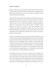
3.3. AGENTS 11 If this information would change this road’s load significantly then call the planRecalculate Load.4. Remove Car Upon receiving message from simulator, decrement Car Count in the database. When count is significantly different (perhaps taken as a percentage or a function <strong>of</strong>capacity) from last time load was calculated, then call Recalculate Load 4 .5. Send Load Downstream Send load to all downstream roads in the Downstream Load Percent table in thedatabase. This is done using the Tell Send plan as we cannot have an action insideanother.6. Send Load Intersection Receive message asking for load from intersection. Call the Recalculate Load plan. Send the load back to the intersection.7. Tell Send Sends the load it is passed to the <strong>agent</strong> it is passed.3.3.2 Intersection AgentThese <strong>agent</strong>s are responsible for each intersection. They handle the control <strong>of</strong> the traffic throughthe traffic lights. Originally they will simply change the timing <strong>of</strong> the lights to allow the‘best’ 5 traffic flow in only two directions (ie. no turning arrows — these could be incorporatedlater). The basis <strong>of</strong> the <strong>agent</strong>’s strategy is an algorithm which, given the loads <strong>of</strong> all incomingroads, decides whether to change out <strong>of</strong> its current state, and therefore, into the next one in apredetermined sequence. This sequence is implemented in the Change Lights plan and so canbe changed (or discarded altogether) very easily.Database Entries1. Current StateSimply stores the current state <strong>of</strong> the lights. It is used to decide on the changes necessaryto move to a new state in the Change Lights plan. It is simply a list consisting <strong>of</strong> the letters”r” and ”g” showing the state <strong>of</strong> each set <strong>of</strong> lights with the northern-most lights being thefirst position and continuing clockwise (see figure 3.1).4 Not yet implemented5 There needs to be more discussion about what comprises an optimal solution to this problem
12 CHAPTER 3. DESIGN OF THE TRAFFIC-FLOW CONTROL SYSTEMN12534Figure 3.1: <strong>Traffic</strong> Light Numbering2. Poll TimeThis is simply the time interval after which the intersection <strong>agent</strong> will poll the incomingroads and calculate whether it should change out <strong>of</strong> its current state. A good starting valuewould be something around ten seconds.3. Poll CountCounts the number <strong>of</strong> polls that have occurred while in this traffic light state. This allowsthe <strong>agent</strong> to calculate whether or not it should change state based on how long it hasbeen in the current state. That is, the time since the last change will be (Poll Time *Poll Count).4. Street LoadsThis is a table <strong>of</strong> the incoming streets, their order in the Current State list, whether it isthe load going straight or turning and their respective loads. These are the streets that theintersection polls to calculate its strategy about the timing <strong>of</strong> state changes. When theloads <strong>of</strong> these streets are received they are put into this table. For example:List Number Agent Name Direction Load1 Russell 4 straight 342 Collins 3 straight 673 Russell 5 straight 434 Collins 4 straight 755. Light StatesThis is a table showing all the possible states, the order in which these states are usuallycycled through, and the current priority <strong>of</strong> each <strong>of</strong> these states.State Number State Priority1 rgrg 772 grgr 1426. Number StatesThis contains the number <strong>of</strong> states in the Light States table.
3.3. AGENTS 13CommunicationThese <strong>agent</strong>s will communicate with incoming street <strong>agent</strong>s, the simulator, and maycommunicate with neighbouring intersection <strong>agent</strong>s 6 . They will poll the incoming street <strong>agent</strong>sfor load information which they will use to calculate state changes for the intersection’s trafficlights. This will occur every Poll Time seconds, so obviously changes can only occur with thisgranularity.Plans1. Change Lights Call the Change State plan with the current state and the next state. Set Poll Count to zero in the database.2. Change State Call the Calculate Intermediate State plan. Change lights to this intermediate state 7 and call the Notify Simulator plan. Wait for a given time (say, three seconds). Change lights from the Current State to the next state in the sequence. Call the Notify Simulator plan.3. Poll Streets For every street in the Street Loads table database entry, call Poll Street. For each state in Light States table, call Calculate Combined Load. Increment Poll Count in the database. This will happen every Poll Time seconds until the lights change 8 .4. Poll Street Ask this street for its load. Store returned information in Street Loads database.5. Calculate Combined LoadThis plan and Calculate Combined Load0 recursively calculate the loads. The existingplans need to be amended to only add in the loads <strong>of</strong> the streets which are green for eachstate. The changing <strong>of</strong> the database in the success condition also needs to be checked, asit may lead to an assert being done on every recursive call — very wasteful. Add the load on each street that has a green light in the given state.6 If we manage (or even decide) to implement agreement <strong>of</strong> changes between intersections then thiscommunication will be necessary — see Future Expansions (section 3.4) below.7 In the real world.8 This still needs to be implemented.
14 CHAPTER 3. DESIGN OF THE TRAFFIC-FLOW CONTROL SYSTEM Incorporate some function <strong>of</strong> the time since last change (Poll Time * Poll Count). Store total in Light States table entry.6. Decide Change State Calculate whether to change out <strong>of</strong> the current state based on priorities inLight States. If change should occur then call Change Lights.3.4 Future Expansions3.4.1 Global StrategiesIt may seem ridiculous to discuss global strategies when we are taking an emergent behaviorapproach with localized communication, but we believe that an understanding <strong>of</strong> the desiredbehavior <strong>of</strong> the system is necessary before one can adequately design the system’s localizedparts (ie. the street and intersection <strong>agent</strong>s). Obviously the simplest strategy is to regulate thetiming given to each cross street taking into account the respective loads, and this is probablythe best way to begin the implementation. The following discussion will hopefully be usefulif (or when) we change this strategy into something more advanced. The implementation<strong>of</strong> these strategies (coordination <strong>of</strong> the changes <strong>of</strong> lights) is not intuitive with the emergentbehavior approach we have chosen — it would require some sort <strong>of</strong> agreement to be reachedwith neighbouring intersections before any state changes were made. This is certainly possible,but it would be difficult and it is hard to comment on its effectiveness.If we were to implement these types <strong>of</strong> strategies we believe we would need to cope withthree different scenarios:1. Heavy <strong>Traffic</strong> Loads2. Medium <strong>Traffic</strong> Loads3. Light <strong>Traffic</strong> LoadsThese three scenarios are sufficiently different that the system should respond differently to eachone. We discuss each in detail below.In these discussions we use the terms entrance and exit ends <strong>of</strong> a road stretch. Theserepresent the ends <strong>of</strong> a stretch <strong>of</strong> road (which may contain one or more intersections andtherefore one or more road sections) by which cars enter and leave respectively. It is thereforeobvious that any entrance is also an exit in the opposite direction. We will discuss only a singledirection here for reasons <strong>of</strong> simplification. This is an important point as it may occur that onedirection is heavily loaded and the other lightly loaded; as one set <strong>of</strong> lights must control bothdirections a single strategy must be decided upon 9 . Probably the simplest method is to use astrategy which will help the most cars (ie. give preference to the heavily-loaded direction). Youwill notice that some <strong>of</strong> the particular strategies outlined below will perform favourably withuneven loading in the two directions.9 These complications may mean that implementing these global strategies with the type <strong>of</strong> system we havediscussed will be impossible
3.5. DISCUSSION 15Heavy <strong>Traffic</strong> LoadsBecause the roads are heavily loaded, cars are bound to encounter a queue <strong>of</strong> cars at the nextintersection very soon after leaving the one they are waiting at. This means that making a lightgreen in the middle <strong>of</strong> the stretch <strong>of</strong> loaded road is almost useless. The obvious solution is tobegin making lights green at the exit from the stretch first, then hopefully when cars are allowedto go, they haven’t got a blockage in front <strong>of</strong> them.Medium <strong>Traffic</strong> LoadsThis seems to be the situation in which lights on a stretch <strong>of</strong> road should be synchronized to gogreen simultaneously. This means that traffic taking <strong>of</strong>f from one light will not be slowed bythe traffic only just starting <strong>of</strong>f from the next light.Light <strong>Traffic</strong> LoadsIn this situation it would be good if the lights were synchronized so that cars get a clear run alongthe stretch <strong>of</strong> road. For example, if a car was stopped at the entrance, when it got a green lightall the lights in front <strong>of</strong> it should be green by the time the car gets to them. Therefore lights atthe entrance should go green first and the change should propagate along the road stretch at anappropriate speed. It should be obvious that this would lead to the cars in the opposite directiongetting the treatment for a heavy load (which may be an advantage at peak hour times).3.5 DiscussionThis design had the advantage that in its most basic form it was readily understandable andtherefore implementable within our time constraints. It does not require an in-depth knowledge<strong>of</strong> the global systematic strategies <strong>of</strong> traffic flow, although this may be an advantage in laterrefinement. As a system it would be easily expanded because <strong>of</strong> its modular design, and anyexpansions would only incur linearly growing costs in terms <strong>of</strong> communications and no drop inresponse time.The quality <strong>of</strong> the solution is hard to judge at this stage, partly because we haven’tadequately defined what a quality solution would be, and also because the very nature <strong>of</strong> anemergent behavior system means that its behavior is relatively unpredictable at the design stage.
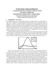
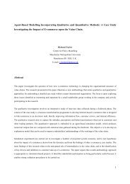
Chapter 4<strong>Traffic</strong>-<strong>Flow</strong> <strong>Control</strong>: Simulator <strong>Design</strong>4.1 IntroductionIn this chapter, we describe in detail the design <strong>of</strong> the traffic flow simulator. Intersections andtraffic lights will be modeled using dMARS <strong>agent</strong>s, and road sections will be just a part <strong>of</strong> these<strong>agent</strong>s.Much <strong>of</strong> this chapter is not relevant to those wishing only to use the simulator as a model <strong>of</strong>the real world. For them, the only part which will be <strong>of</strong> interest is section 4.5, where we outlinethe interface between the simulator and the controlling <strong>agent</strong>s.The only external control available is to specify changes to the state <strong>of</strong> the traffic lights.The simulator also sends out a message whenever a car moves into or out-<strong>of</strong> a road segment.No other interaction occurs between the simulator and the outside world.Using dMARS <strong>agent</strong>s for the implementation has the effect <strong>of</strong> simplifying the code required.It also has efficiency advantages over a UNIX process-based implementation, since contextswitching within a dMARS <strong>agent</strong> is much more efficient than context switching entire UNIXprocesses.4.2 An Intersection Agent4.2.1 IntersectionsEvery intersection is being modeled as an <strong>agent</strong>. The intersection <strong>agent</strong> will handle trafficflowing into it from any neighbouring upstream intersection <strong>agent</strong>s, and pass vehicles on todownstream <strong>agent</strong>s. The way in which it passes them down is governed by a number <strong>of</strong> factors: The current state <strong>of</strong> the traffic lights, that is, the colors currently being shown in everydirection, The number <strong>of</strong> cars wishing to turn <strong>of</strong>f into other streets (the proportion <strong>of</strong> the total flowwishing to turn <strong>of</strong>f is determined within each intersection <strong>agent</strong>), The ability <strong>of</strong> any downstream road segments to take up the vehicles, and The amount <strong>of</strong> time it takes for a vehicle to cross the intersection.16
4.2. AN INTERSECTION AGENT 17Intersection<strong>agent</strong>55 cars33 sec4216GNumber <strong>of</strong> carstravelling in thisdirectionSignal state forthat direction35 cars18 sec58R3 secR01222 cars10 secGCurrentintersectioncrossing timeNumber <strong>of</strong>cars waitingto enterRoadsegment21140 cars23 secRoad segmentcapacity and traveltime to nextintersectionFigure 4.1: The information with which the intersection <strong>agent</strong> operates.For realism, the amount <strong>of</strong> time it takes for a vehicle to cross an intersection should varyover time. When an intersection has just changed state to green for a given direction, the frontvehicles take a while to accelerate and cross the intersection. The cars behind take less time,since they have already started moving by the time the others have passed through. To simulatethis behaviour, the intersection <strong>agent</strong> must be able to realistically alter the period <strong>of</strong> time it takesa vehicle to cross the intersection. It should be set to the highest value at the moment a light turnsgreen, then quickly decay to a shorter period <strong>of</strong> time.4.2.2 Road SegmentsEach <strong>agent</strong> is responsible for the half <strong>of</strong> the road segment leading away from the intersection 1 .Since the intersection <strong>agent</strong> knows the capacities <strong>of</strong> these segments, and the number <strong>of</strong> carscurrently traveling along them, it can easily decide how many more cars can be accepted fromthe upstream <strong>agent</strong>s. Figure 4.1 outlines the information used by an intersection <strong>agent</strong>, andfigure 4.2 shows the <strong>agent</strong>s’ responsibility for any downstream road segments.1 Because this program is being written in Australia, all our figures will assume that vehicles drive on theleft-hand side <strong>of</strong> the road. The simulator <strong>agent</strong>s don’t depend upon this information, they only need the identities<strong>of</strong> the downstream <strong>agent</strong>s. The simulator can be used anywhere in the world.
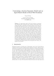
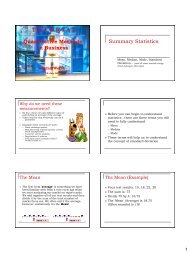
18 CHAPTER 4. TRAFFIC-FLOW CONTROL: SIMULATOR DESIGNAgent 1Agent 2Inter−<strong>agent</strong>communicationsFigure 4.2: Overview <strong>of</strong> the flow <strong>of</strong> information between any pair <strong>of</strong> adjacent intersection<strong>agent</strong>s.The intersection <strong>agent</strong>s are also responsible for simulating the traveling time for vehiclesmoving along those stretches <strong>of</strong> road. In particular, the specific time periods involved are: The amount <strong>of</strong> time that it takes a vehicle to travel along a segment to the next downstreamintersection, and The amount <strong>of</strong> time it takes for a vehicle to cross the intersection (see section 4.2.1 abovefor more on how this value is manipulated).4.2.3 Inter-<strong>agent</strong> CommunicationsIn this section, we discuss the information passed between any pair <strong>of</strong> neighbouring intersection<strong>agent</strong>s. (Details <strong>of</strong> the interaction between the simulator <strong>agent</strong>s and the controller <strong>agent</strong>s isdiscussed in section 4.5.) A typical layout <strong>of</strong> a pair <strong>of</strong> <strong>agent</strong>s is given in figure 4.2, showingthe flow <strong>of</strong> vehicles and information. The circled portion <strong>of</strong> the diagram is discussed in detailhere.There are two types <strong>of</strong> messages exchanged between neighbouring intersection <strong>agent</strong>s: sensor_trip $from (sent from Agent 2 to Agent 1)indicating that there is now another car waiting at the entrance to the downstreamintersection <strong>agent</strong> (coming from the <strong>agent</strong> given in the variable $from), and car_entered $from (sent from Agent 1 to Agent 2)which is sent back to an upstream <strong>agent</strong> indicating that the car has been accepted and isnow moving along a road segment.
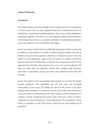
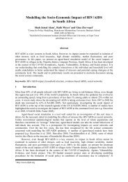
4.2. AN INTERSECTION AGENT 19Intersection<strong>agent</strong>35 cars18 secWG3 secSNumber <strong>of</strong>vehicles in thesegmentNumber <strong>of</strong>vehicles waitingto enter from thisdirectionCurrent signal statefor this directionCurrent intersectioncrossing timeFigure 4.3: The data structures used within the intersection <strong>agent</strong>s to control the flow <strong>of</strong> vehiclesalong road segments.Note that for every sensor_trip sent forward, there should be a correspondingcar_entered sent back, to ensure correct book-keeping.4.2.4 Internal Data StructuresIn this section we outline the data structures needed for the various parts <strong>of</strong> an intersection <strong>agent</strong>.Figure 4.3 shows part <strong>of</strong> an intersection, labeled with the various counters and database entriesused at the indicated points.The messages received from neighbouring <strong>agent</strong>s (section 4.2.3) and controlling <strong>agent</strong>soutside the simulator (section 4.5) are used to modify some <strong>of</strong> these database entries. Othersare modified using various time-out mechanisms. Specifically: As has been mentioned in section 4.2.1, the intersection crossing time is modified usinga time-out mechanism initiated whenever any <strong>of</strong> the lights turn green. For simplicity wehave assumed that this travel time is identical for all directions. The crossing period isused to simulate the acceleration <strong>of</strong> traffic when lights change from red to green. It willdecay quickly to a one-second traversal time. The signal state is modified whenever the controller <strong>agent</strong> sends a message requestingthere be a change <strong>of</strong> color. The W counter keeps track <strong>of</strong> the number <strong>of</strong> vehicles that are waiting to enter fromthe indicated direction. It is incremented every time the intersection <strong>agent</strong> receives asensor_trip message, and decremented every time one <strong>of</strong> the vehicles enters a roadsegment. Decrementing also requires that this <strong>agent</strong> sends a car_entered messageback to the upstream <strong>agent</strong>. The S counter keeps a count <strong>of</strong> the number <strong>of</strong> vehicles that are traveling along a roadsegment. We must ensure this counter never exceeds the segment’s capacity.
20 CHAPTER 4. TRAFFIC-FLOW CONTROL: SIMULATOR DESIGNThese data structures are stored in the intersection <strong>agent</strong>’s private database. We outline belowthe extensional databases used by the <strong>agent</strong>, listing the names <strong>of</strong> the relation, their fields, andany aliases we have used for the relation.Upstream Agent NamesUpstream Agent Name relates the upstream intersection <strong>agent</strong>’s name with the correspondingincoming direction identifier. The direction identifier is the key field.Upstream Agent Namesupstream <strong>agent</strong>Incoming Direction IdI dir idAgent Namea nameAliases: upstreamDownstream Agent NamesMuch like the predicate above, Downstream Agent Names relates the downstream <strong>agent</strong>’s nameto its direction identifier. The direction identifier is the key field.Downstream Agent Namesdownstream <strong>agent</strong>Outgoing Direction Id Agent NameO dir id a nameAliases: downstreamIncoming Segment <strong>Control</strong>ler AgentThis relates the <strong>agent</strong>s needed to be notified <strong>of</strong> vehicle movements to direction identifiers. Thedirection identifier is the key field.Incoming Segment <strong>Control</strong>ler Agentcontroller <strong>agent</strong> IIncoming Direction Id <strong>Control</strong>ler Agent NameI dir ida nameAliases: (none)Outgoing Segment <strong>Control</strong>ler AgentThis relates the <strong>agent</strong>s needed to be notified <strong>of</strong> vehicle movements to direction identifiers. Thedirection identifier is the key field.
4.2. AN INTERSECTION AGENT 21Outgoing Segment <strong>Control</strong>ler Agentcontroller <strong>agent</strong> OOutgoing Direction Id <strong>Control</strong>ler Agent NameO dir ida nameAliases: (none)Outgoing Segment Vehicle DistributionThis relation is used to distribute incoming vehicles to the outgoing segments. Any incomingvehicle accepted from direction I dir id will be randomly sent to any <strong>of</strong> the downstream<strong>agent</strong>s based on the probabilities listed. I dir id is the key field.Outgoing Segment Vehicle Distributionvehicle distributionIncoming Direction Id Outgoing Direction Probability ListI dir idO dir prsAliases: distributionOutgoing Segment LimitsThis relates the outgoing segment identifiers to the particular road segment’s physical limits.The key field is O dir id.Outgoing Segment Limitsoutgoing segment limitsOutgoing Direction Id Segment Capacity Travel TimeO dir id cap timeAliases: limit<strong>Traffic</strong> Light StatesThis relation is used to store the current state <strong>of</strong> the traffic lights for all incoming directions.<strong>Traffic</strong> Light Statestraffic light statesIncoming Direction Id <strong>Traffic</strong> Light ColorI dir idcolorAliases: traffic light
22 CHAPTER 4. TRAFFIC-FLOW CONTROL: SIMULATOR DESIGNIncoming Vehicle CounterThis relation is used to store the number <strong>of</strong> vehicles waiting to enter from all incomingdirections. I dir id is the key field.Incoming Vehicle Counterincoming cntrIncoming Direction Id Waiting counterI dir idwAliases: i cntrOutgoing Vehicle CounterThis relation is used to store the number <strong>of</strong> vehicles traveling along the road segments leadingfrom the intersection. O dir id is the key field.Outgoing Vehicle Counteroutgoing cntrOutgoing Direction Id Segment counterO dir idSAliases: o cntrIntersection Traversal TimeThis relation is used to store the time required for a vehicle to cross the intersection. There is nokey field since there can only ever be one entry stored within - the current traversal time period.Intersection Traversal Timetraversal timeTraversal delaydelayAliases: (none)4.2.5 An Example RunIn this section, we outline a sample set <strong>of</strong> interactions between intersection <strong>agent</strong>s (set upmuch like figure 4.2), focusing on the events occurring as an individual car moves through anintersection. This is taken from the point <strong>of</strong> view <strong>of</strong> a typical intersection (such as the one infigure 4.3). Assuming a car wishes to enter from an upstream road segment:1. The upstream <strong>agent</strong> sends a sensor_trip to the <strong>agent</strong>, indicating that a car is waitingto enter the intersection.2. The W counter for that direction is incremented.
4.3. A VEHICLE SOURCE 233. If: the light is green for this direction, there is room in the chosen downstream road segment, and the waiting period (intersection crossing time) has expired since a vehicle was lastsent down from this direction,we can send a car_entered message back to the upstream <strong>agent</strong> and decrement theW counter.4. We increment the S counter for the chosen direction, schedule a message to be sent tothe appropriate downstream intersection <strong>agent</strong> in 18 seconds time (the segment traversaltime), and re-schedule another waiting period timeout to allow another car to cross theintersection.5. When the 18 seconds have expired, this <strong>agent</strong> will send a sensor_trip to thedownstream intersection <strong>agent</strong>.6. Eventually the downstream <strong>agent</strong> will send this <strong>agent</strong> a car_entered message. Wecan now decrement S for that direction, as the vehicle has just entered the downstreamintersection.4.3 A Vehicle SourceThe vehicle source will generate vehicles for the simulator, and pass them on to downstream<strong>agent</strong>s. It may be used with various sources <strong>of</strong> information, such as input files outlining numbersand times <strong>of</strong> cars desired or real-life load information, or can internally generate random flows<strong>of</strong> vehicles.Such a program is available for dMARS; an <strong>agent</strong> is not needed for this task. A non-existent<strong>agent</strong> name is given as a return address in the (sensor_trip $from) message. 24.4 A Vehicle SinkThe job <strong>of</strong> a vehicle sink is to be an unlimited sponge <strong>of</strong> vehicles. It can be considered the edge<strong>of</strong> our simple simulated “flat world”, where everything reaching the edge just falls over, neverto be seen again.As far as any upstream intersection <strong>agent</strong> is concerned, a vehicle sink should respond likeany other intersection <strong>agent</strong>. It will differ in that it never halts the flow <strong>of</strong> vehicles entering; it’saction is to respond immediately to every sensor_trip message sent with a car_enteredmessage.Only one such <strong>agent</strong> is needed for the entire simulator; sensor_trip messages arealways sent with return addresses, so any number <strong>of</strong> <strong>agent</strong>s can have this one “sink” <strong>agent</strong> as a“downstream intersection”.2 This relies on the fact that the dMARS communication manager will ignore messages sent to non-existent<strong>agent</strong>s. If the manager were to cause a fatal error on this event, a real <strong>agent</strong> would be needed to harmlessly absorbthese redundant messages.
24 CHAPTER 4. TRAFFIC-FLOW CONTROL: SIMULATOR DESIGN4.5 External CommunicationsIn this section we discuss the content and form <strong>of</strong> the communications sent between intersection<strong>agent</strong>s and the external <strong>agent</strong>s controlling the intersection. (See section 4.2.3 for discussion <strong>of</strong>the communications internal to the simulator).The only control any external <strong>agent</strong>s can exercise over the intersection is to change thecurrent state <strong>of</strong> the traffic lights. There is no verification <strong>of</strong> the identity <strong>of</strong> an <strong>agent</strong> requestingtraffic light state changes; they are taken on faith.The form <strong>of</strong> the message to change traffic lights is: (change traffic lights $list <strong>of</strong> states)where $list <strong>of</strong> states is a list <strong>of</strong> colors. The order followed is clockwise fromNorth; so the first element in the list is for the first incoming direction found whentraveling clockwise from North, the second element is for the second light, and so on.The terms contained in the list are simply either “r” or“g”.If the list is shorter than the actual number <strong>of</strong> lights, those not addressed remain in theirprevious states.The form <strong>of</strong> the messages sent out from the simulator <strong>agent</strong> whenever a vehicle passes out-<strong>of</strong>or in-to a segment is: (car entered), and (car exited).Note that this assumes controller <strong>agent</strong>s are monitoring vehicles moving between road segmentsrather than into intersections. Although the messages look like the messages used for simulatorinter-<strong>agent</strong> communications (from section 4.2.3), their purpose is different.
Chapter 5DiscussionIt is unfortunate that we were unable to run our system. The problems were the incompletestate <strong>of</strong> dMARS, which made it hard to test our code, and the limited time we had in which toimplement the system. There were also some things we needed to decide before we could finishthe project: We intended to have a number <strong>of</strong> controllers, implementing different types <strong>of</strong> controlstrategy, and evaluating their effectiveness. Initially, two strategies were proposed; theemergent-behavior approach (which we did implement), and the hierarchical-controlapproach (which we did not).We would like to have had both represented; time and conflicting needs halted this line<strong>of</strong> research. The competitive nature <strong>of</strong> the above strategies required performance monitoring metricsand criteria to be decided. Also, a realistic performance monitoring system is needed toevaluate any solution we did implement. We currently have not decided how this is to bedone.25
Appendix A<strong>System</strong> Street PlansFigure A.1: Add Car26
27Figure A.2: Recalculate LoadFigure A.3: Receive Load Upstream
28 APPENDIX A. SYSTEM STREET PLANSFigure A.4: Remove CarFigure A.5: Send Load Downstream
29Figure A.6: Send Load IntersectionFigure A.7: Tell Send
Appendix B<strong>System</strong> Intersection PlansFigure B.1: Change Lights30
31Figure B.2: Change StateFigure B.3: Calculate Combined Loads
32 APPENDIX B. SYSTEM INTERSECTION PLANSFigure B.4: Calculate Combined Loads0Figure B.5: Decide Change State
33Figure B.6: Calculate Intermediate StateFigure B.7: Calculate Intermediate State0
34 APPENDIX B. SYSTEM INTERSECTION PLANSFigure B.8: Notify SimulatorFigure B.9: Poll Streets
Figure B.10: Poll Street35
Appendix CSimulator PlansINVOCATION(*add-fact (monitor_segment $o_dir_id))CONTEXT(and(*fact (downstream $o_dir_id $downstream_<strong>agent</strong>))(*fact (controller_<strong>agent</strong>_O $o_dir_id $controller_<strong>agent</strong>))(*fact (limit $o_dir_id $capacity $travel_time)))PROPERTIES((priority 10))START(* (tell (car_entered) $controller_<strong>agent</strong>))P1(^ (elapsed $travel_time))P3(* (tell (sensor_trip (<strong>agent</strong>-name)) $downstream_<strong>agent</strong>))END1Figure C.1: The plan: monitor segment. Initiated whenever a vehicle enters a downstreamsegment. It takes care <strong>of</strong> one vehicle’s traversal; its timing and notification <strong>of</strong> downstreamsegments.36
37INVOCATION(*add-fact (monitor_incoming $i_dir_id))CONTEXT(and (*fact (controller_<strong>agent</strong>_I $i_dir_id$controller_<strong>agent</strong>))(*fact (distribution $i_dir_id $probabilities))(*fact (upstream_<strong>agent</strong> $i_dir_id $upstream_<strong>agent</strong>)))PROPERTIES((priority 10))STARTotherwiseotherwise(? (traffic_light $i_dir_id g))P1otherwise(! (nonzero_i_cntr $i_dir_id))END1P2(! (select_direction $probablilties $destination))P3(* (=> (monitor_segment $destination)))(! (increment_o_cntr $destination))P4(! (decrement_i_cntr $i_dir_id))P5(* (tell (car_exited) $controller_<strong>agent</strong>))P9(* (tell (car_entered (<strong>agent</strong>_name)) $upstream_<strong>agent</strong>))P8(? (traversal_time $delay))P6(^ (elapsed $delay))P7Figure C.2: The plan: monitor incoming. Initiated when a light turns green for a givendirection, and takes care <strong>of</strong> intersection traversal timeouts for individual vehicles.
38 APPENDIX C. SIMULATOR PLANSINVOCATION(*goal (!(select_direction $probabilities $result)))CONTEXTTPROPERTIES((priority 10))START(* (= $random (erand48 666)))P4(* (@= @cumulative_prob 0))P9(* (@= @tl $probabilities))P8(* (@= @pos 1))P5(? (isempty @tl))otherwiseP6(* (:= $result @pos))P1(* (@= @hd (first @tl)))END1P2(* (@= @tl (rest @tl)))(* (@= @pos (+ 1 @pos)))(? (
39INVOCATION(*goal (!(decrement_o_cntr $o_dir_id)))CONTEXTTPROPERTIES((priority 5))START(? (o_cntr $o_dir_id $s))P4(? (> $s 0)) otherwiseP2P5(* (=> (o_cntr $o_dir_id (- $s 1))))NILEND3END2Figure C.4: The plan: decrement o cntr. Decrements an outgoing segment counter. Itshigh priority ensures it is atomically executed (never pre-empted).INVOCATION(*goal (!(increment_o_cntr $o_dir_id)))CONTEXT(*fact (limit $o_dir_id $limit $time))PROPERTIES((priority 5))START(? (o_cntr $o_dir_id $s))P4(? (< $s $limit)) otherwiseP2(* (=> (o_cntr $o_dir_id (+ $s 1))))P5NILEND3END2Figure C.5: The plan: increment o cntr. Increments an outgoing segment counter. (Thisis atomic also.)
40 APPENDIX C. SIMULATOR PLANSINVOCATION(*goal (!(decrement_i_cntr $i_dir_id)))CONTEXTTSTARTPROPERTIES((priority 5))(? (i_cntr $i_dir_id $w))P4(? (> $w 0)) otherwiseP2P5(* (=> (i_cntr $i_dir_id (- $w 1))))NILEND3END2Figure C.6: The plan: decrement i cntr. Decrements an incoming segment counter.(Atomic)INVOCATION(*goal (!(increment_i_cntr $i_dir_id)))CONTEXTTPROPERTIES((priority 5))START(? (i_cntr $i_dir_id $w))P2(* (=> (i_cntr $i_dir_id (+ $w 1))))END1Figure C.7: The plan: increment i cntr.(Atomic)Increments an incoming segment counter.
41INVOCATION(*goal (!(nonzero_i_cntr $i_dir_id)))CONTEXTTPROPERTIES((priority 5))START(? (i_cntr $i_dir_id $w))P4(? (> $w 0))END1Figure C.8: The plan: nonzero i cntr. Atomically test if an incoming segment counter isnon-zero.INVOCATION(*goal (!(change_lights $i_dir_id $statesCONTEXT(*fact (isempty $states))PROPERTIES((priority 9))Figure C.9: The plan: change lights ma[]. Changes traffic lights: the plan when the list<strong>of</strong> states is empty.
42 APPENDIX C. SIMULATOR PLANSINVOCATION(*goal (! (change_lights $i_dir_id $states)))CONTEXT(*fact (~ (isempty $states)))PROPERTIES((priority 9))START(* (:= $x (first $states)))P1(* (:= $xs (rest $states)))P2(* (:= $nextid (+ $i_dir_id 1)))P3(* (=> (traffic_light $i_dir_id $x)))P4(! (change_lights $next_id $xs))END1Figure C.10: The plan: change lights (x:xs). Changes traffic lights: the plan when thelist <strong>of</strong> states is non-empty. Recurses through the list, updating the appropriate database entries.
43INVOCATION(*told (change_traffic_lights $states) told $_)CONTEXTTPROPERTIES((priority 9))START(* (=> (traversal_time 3)))P1(! (change_lights 1 $states))END1Figure C.11: The plan: told change traffic lights. Catches the ‘told’ message fromthe controller <strong>agent</strong>, spawns the intersection delay decay plan, and the plan to recursively changethe traffic light database.INVOCATION(*add-fact (traffic_light $i_dir_id $color))CONTEXT(*fact (== $color g))PROPERTIES((priority 9))EFFECTS( (=> (monitor_incoming $i_dir_id)) )Figure C.12: The plan: spawn direction monitor. This notices that a traffic light hasturned green, and spawns a direction monitor plan to watch over that direction.
44 APPENDIX C. SIMULATOR PLANSINVOCATION(*add-fact (traversal_time $delay))CONTEXT(*fact (> $delay 1))PROPERTIES((priority 9))START(^ (elapsed 1))P1(* (=> (traversal_time (- $delay 1))))END1Figure C.13: The plan: traversal time decay. Decays the intersection traversal timeslowly to one second.INVOCATION(*told (sensor_trip $from) told $_)CONTEXT(*fact (upstream $i_dir_id $from))PROPERTIES((priority 10))START(! (increment_i_cntr $i_dir_id))END1Figure C.14: The plan: told sensor trip. Catches the message sent when upstreamintersection <strong>agent</strong>s tell this one that there is now another car waiting to enter the intersection.Increments the appropriate counter.
45INVOCATION(*told (car_entered $to) told $_)CONTEXT(*fact (downstream $o_dir_id $to))PROPERTIES((priority 10))START(! (decrement_o_cntr $o_dir_id))END1Figure C.15: The plan: told car entered. Catches the message sent when downstreamintersection <strong>agent</strong>s tell this one that another car has entered the downstream intersection.Decrements the appropriate counter.INVOCATION(*told (sensor_trip $from) told $_)CONTEXTTPROPERTIES((priority 10))START(* (tell (car_entered (<strong>agent</strong>_name)) $from))END1Figure C.16: The plan: respond to sensor trip. This is the only plan in the Sink <strong>agent</strong>family. It will echo back a car entered message for every sensor trip message sent to it.It just keeps the intersections’ counters sensible.