i. Module 4 Fluids and Thermodynamics ... - Workforce 3 One
i. Module 4 Fluids and Thermodynamics ... - Workforce 3 One
i. Module 4 Fluids and Thermodynamics ... - Workforce 3 One

Create successful ePaper yourself
Turn your PDF publications into a flip-book with our unique Google optimized e-Paper software.
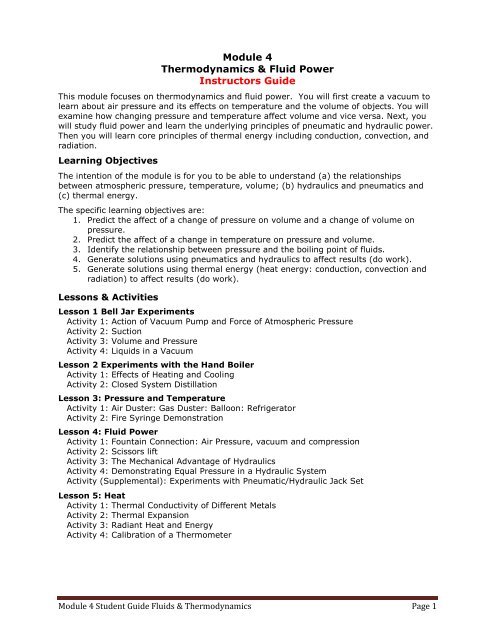
<strong>Module</strong> 4<strong>Thermodynamics</strong> & Fluid PowerInstructors GuideThis module focuses on thermodynamics <strong>and</strong> fluid power. You will first create a vacuum tolearn about air pressure <strong>and</strong> its effects on temperature <strong>and</strong> the volume of objects. You willexamine how changing pressure <strong>and</strong> temperature affect volume <strong>and</strong> vice versa. Next, youwill study fluid power <strong>and</strong> learn the underlying principles of pneumatic <strong>and</strong> hydraulic power.Then you will learn core principles of thermal energy including conduction, convection, <strong>and</strong>radiation.Learning ObjectivesThe intention of the module is for you to be able to underst<strong>and</strong> (a) the relationshipsbetween atmospheric pressure, temperature, volume; (b) hydraulics <strong>and</strong> pneumatics <strong>and</strong>(c) thermal energy.The specific learning objectives are:1. Predict the affect of a change of pressure on volume <strong>and</strong> a change of volume onpressure.2. Predict the affect of a change in temperature on pressure <strong>and</strong> volume.3. Identify the relationship between pressure <strong>and</strong> the boiling point of fluids.4. Generate solutions using pneumatics <strong>and</strong> hydraulics to affect results (do work).5. Generate solutions using thermal energy (heat energy: conduction, convection <strong>and</strong>radiation) to affect results (do work).Lessons & ActivitiesLesson 1 Bell Jar ExperimentsActivity 1: Action of Vacuum Pump <strong>and</strong> Force of Atmospheric PressureActivity 2: SuctionActivity 3: Volume <strong>and</strong> PressureActivity 4: Liquids in a VacuumLesson 2 Experiments with the H<strong>and</strong> BoilerActivity 1: Effects of Heating <strong>and</strong> CoolingActivity 2: Closed System DistillationLesson 3: Pressure <strong>and</strong> TemperatureActivity 1: Air Duster: Gas Duster: Balloon: RefrigeratorActivity 2: Fire Syringe DemonstrationLesson 4: Fluid PowerActivity 1: Fountain Connection: Air Pressure, vacuum <strong>and</strong> compressionActivity 2: Scissors liftActivity 3: The Mechanical Advantage of HydraulicsActivity 4: Demonstrating Equal Pressure in a Hydraulic SystemActivity (Supplemental): Experiments with Pneumatic/Hydraulic Jack SetLesson 5: HeatActivity 1: Thermal Conductivity of Different MetalsActivity 2: Thermal ExpansionActivity 3: Radiant Heat <strong>and</strong> EnergyActivity 4: Calibration of a Thermometer<strong>Module</strong> 4 Student Guide <strong>Fluids</strong> & <strong>Thermodynamics</strong> Page 1
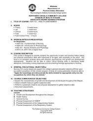
<strong>Module</strong> 4: <strong>Fluids</strong> & <strong>Thermodynamics</strong>Instructors GuideLesson 1: Bell Jar ExperimentsHave students work in groups of 2. Provide each group with the following:Bell Jar SetSilicone based lubricant (to lubricate the orings)Large <strong>and</strong> small marshmallowsCan of shaving creamHot liquid (water or coffee)Small balloonThe micro bell jar enables you to create a vacuum to learn about air pressure <strong>and</strong> its effectson temperature <strong>and</strong> the volume of objects. The syringe <strong>and</strong> one-way check valve systemconstitute the vacuum pump.PartsA – Bell Jar with top connectorB – Bottom PlateC – “O” ringD – Hose with one-way valveE – Hose with T <strong>and</strong> check valveF – SyringeG – Plastic cupH – Suction cupBasic Setup & Operation1. Assemble the Vacuum pump asshown in Figure 1.The fitting from the side-arm of theT connects to the syringe with lightfinger pressure <strong>and</strong> a partial turn.The other fitting connects to part Dwith a partial turn.2. Attach part E to the connector on thetop of the bell jar. (Figure 2)A turn of approximately one-third isall that is needed to make theconnection secure.Do not over-tighten! Figure 1 Figure 2<strong>Module</strong> 4 Student Guide <strong>Fluids</strong> & <strong>Thermodynamics</strong> Page 2
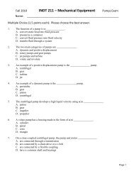
The final assembly of the apparatus isshown in Figure 3.The check valves will easily allow air toflow in the direction shown by thearrows, but not in the other direction.Figure 3Activity 1: Action of Vacuum Pump <strong>and</strong> Force of Atmospheric Pressure1. To create a vacuum, have one person push down on the bell jar to make certain that thebell jar is pressing against the “O” ring. While they are doing this, pull the piston of thesyringe out to the 60 mark.2. Where does the air come from that fills the syringe?The air in the the bell jar3. Let go of the piston <strong>and</strong> watch what happens.4. Now quickly push the piston all the way back into the syringe. Listen for the sound ofmoving air. Where did the air go that was in the syringe?It is pushed out into the room5. Describe in words the amount of force that was required to pull the piston out. Whatkind or kinds of force resisted you as you pulled out the piston?Lack of air pressure in the bell jar <strong>and</strong> air pressure on the syringe plunger.6. Repeat these steps 5 times:• Pull the piston out to the 60ml mark• Let go of the piston <strong>and</strong> see what happens• Push the piston all the way back in.What happened to the amount of force as you followed the steps?It became more <strong>and</strong> more difficult to pull the syringe out7. Try to explain why the amount of the force changed as you completed step 6 above.___________________________________________________________________8. Try pulling the bell jar (A) from its base (C). What’s holding them together?The air pressure pushing the base against the oring. Differenece in pressure from insideto outside<strong>Module</strong> 4 Student Guide <strong>Fluids</strong> & <strong>Thermodynamics</strong> Page 3
9. Loosen the connection between the hose (D) <strong>and</strong> the bell jar. Did you hear airmovement? What was the air doing?It was moving in to fill the vacuum in the bell jar.Activity 2: What is “suction”?1. Press the suction cup onto the inside base of the bell jar. Turn the base upside down <strong>and</strong>make sure the suction cup “sticks” to the base.2. Place the bell jar on the base <strong>and</strong> pump the syringe until you have created a vacuuminside the jar.3. Turn the bell jar upside down. What happened? Suction cup fell4. What was holding the suction cup prior to creating the vacuum?Air pressure on outside of cupActivity 3: Increasing/Reducing Volume by Reducing/Increasing PressureRemoving atmospheric pressure from objectsA rubber balloon has been provided. It is designed to be blown up to a nine inch diameterround shape, but in this activity it will be barely inflated.1. Blow into the balloon until it is tight but not stretched. Then tie it. It should be about7cm long <strong>and</strong> 3 or 4 cm in diameter. Why is the balloon now the size it is, <strong>and</strong> notbigger?2. Place the balloon inside the bell jar <strong>and</strong> attach the pumping apparatus to it. Before youstart pumping the piston predict what you think will happen._______________________________________________________________3. Now start pumping the piston. What happens to the balloon? Why did the balloonchange in the way it did?The balloon inflates, there is more air pressure inside the balloon than inside the bell jar4. Loosen the connection between the hose (D) <strong>and</strong> the bell jar until you hear themovement of air. What happens to the balloon? Why does this change occur?The balloon deflated, the air pressure was the same inside the balloon as out.5. Repeat the balloon experiment using a cup of shaving cream <strong>and</strong>/or a marshmallow.How do you explain the change that occurred to the objects?Marshmallows <strong>and</strong> shaving cream is filled with air. The air exp<strong>and</strong>s when the pressure inthe bell jar is reduced making the marshmallow <strong>and</strong> shaving cream to exp<strong>and</strong>Activity 4: Liquids in a VacuumCan you boil liquids without adding heat?1. Fill the plastic cup halfway with hot tap water or very hot coffee <strong>and</strong> measure thetemperature of the water.<strong>Module</strong> 4 Student Guide <strong>Fluids</strong> & <strong>Thermodynamics</strong> Page 4
2. Place the cup in the bell jar <strong>and</strong> start pumping the piston to create a vacuum.3. What happens as you pump the piston? See if you can get the liquid to “boil”.4. What do think has happened to the temperature of the liquid? It remained the same5. Slowly loosen the connection between the hose <strong>and</strong> the bell jar. Open the bell jar <strong>and</strong>check the temperature of the liquid. What has happened? It remained the same6. Think about the boiling process. The water becomes gas (steam) bubbles. Do you thinkthat the presence of atmospheric pressure helps the boiling process or makes it moredifficult?Decreasing the pressure decreases the boiling point7. How do you think many manufactures in the process industry (food, chemicals, etc)control the “cooking” or reaction process by controlling pressure?8. Pressure cookers allows the items to be cooked at a temperature higher than the boilingpoint of water causing the food to cook faster <strong>and</strong> also killing harmful bacteria.Lesson 2: Experiments with the H<strong>and</strong> BoilerProvide each student with a h<strong>and</strong> boiler. At the end of the experiment collect the h<strong>and</strong>boiler <strong>and</strong> retain for use in the chemistry sectionActivity 1: H<strong>and</strong> Boiler: Effects of Heat & Cooling (effects of temperature differential)CAUTION: The H<strong>and</strong> Boiler contains Ethyl Alcohol – DO NOT use near heat or flames.1. Place the larger glass bulb in your h<strong>and</strong> <strong>and</strong> wrap your fingers around it <strong>and</strong> watch whathappens. Your body heat causes the liquid to move into the top bulb <strong>and</strong> appear to boil.How does it work?As the temperature of ethanol increases the vapor pressure increases. The increased gaspressure in the bottom bulb pushes the solution into the top bulb. The solution neverreally boils; however, it just appears to boil when the bottom bulb empties, <strong>and</strong> thevapor is bubbled up through the upper solution.Specifically:1) The warmth causes the vapor pressure to increase enough to push the ethanolthrough the tube <strong>and</strong> into the upper bulb.2) When the liquid level in that bulb drops below the level of the extended tube, thenthe vapor itself is pushed up through the tube.<strong>Module</strong> 4 Student Guide <strong>Fluids</strong> & <strong>Thermodynamics</strong> Page 5
3) As the vapor bubbles up through the ethanol in the top bulb it gives the appearanceof rapid boiling.4) This bubbling lasts several seconds until the pressures equalizes in the two bulbs.5) At this point the upper bulb can be warmed to push the ethanol back down into thelower bulb.2. Hold the lower bulb until the “boiling” stops to demonstrate that the pressures are inbalance. Set the boiler on the desk <strong>and</strong> see how long it takes for the liquid to drop backdown to the bottom bulb.3. Hold the lower bulb again until all the liquid is pushed up. Then hold the upper bulb <strong>and</strong>see if the liquid is pushed back down.4. What do you think will happen if you hold both bulbs at the same time? Test yourprediction.Lesson 3: Pressure <strong>and</strong> TemperatureActivity 1: Air DusterProvide each student with a balloon <strong>and</strong> have several cans of compressed air (dust remover)available for the students to useA. How Air Duster Works1. Hold the can upright <strong>and</strong> spray.2. Note what happens to the temperature of the can.Why does the can get so cold?Gas duster, also known as canned air or Air Duster, contains gases inside that have beencompressed to the point that they have become liquid, <strong>and</strong> they evaporate before leavingthe can since the valve draws from the top (unlike most aerosol cans which have a strawthat draws from the bottom of the can). Despite the name "canned air," the cans actuallycontain inert gases that are much easier to compress into liquids, such as difluoroethane.When the can is held upright <strong>and</strong> activated, gas flows out through the nozzle. The pressureinside the can therefore drops, <strong>and</strong> is no longer sufficient to keep the contents as a liquid;so some of the liquid boils, until the equilibrium pressure is re-established. As vaporizationof a liquid occurs heat is absorbed <strong>and</strong> the can becomes cold.If the can is held upside down, then its contents are expelled as a liquid. This liquidevaporates very quickly at st<strong>and</strong>ard temperature <strong>and</strong> pressure, chilling anything in contactwith it. This process can produce very cold temperatures, easily sufficient to cause frostbite.Similar cans with dip tubes are marketed as "freeze spray," <strong>and</strong> will expel liquid when heldright side up.Safety: Inhaling the gas can cause death, paralysis, or serious injuryBecause of the generic name "canned air", some people mistakenly believe that the canonly contains normal air or contains a less harmful substance known as nitrous oxide.However, the gas is denser than air. Inhaling the gas can cause death, paralysis, orserious injury. Recently, in the United States <strong>and</strong> Canada stores have begun to ask for IDto verify if the customer is 18 years or older.<strong>Module</strong> 4 Student Guide <strong>Fluids</strong> & <strong>Thermodynamics</strong> Page 6
B. Freeze a balloonEver wanted to freeze balloons so they shrivel up? But you couldn't get your h<strong>and</strong>s onindustrial quality liquid nitrogen? We can do it with our Air Duster.Materials: Can of Air Duster, Tweezers or something to hold the balloon so your h<strong>and</strong>s won’tfreeze.1. Fill the Balloon with the gas from the Air Duster, not air. Then tie off the balloon <strong>and</strong>hold on to it by using "your means of holding the balloon"2. Turn the Air Duster upside down <strong>and</strong> spray the balloon. Watch the balloon shrivel up <strong>and</strong>frost form on it.3. How does it work?The gas is in a liquid form as it exits the can, but as it contacts the balloon, the liquidevaporates. The resulting rapid evaporation of liquid gas (oxymoron) takes some of theballoons heats with it, making the balloon shrivel up.C. Evaporation absorbs heat1. Rub some alcohol on your skin2. Notice how cool it feels as it evaporatesHow Refrigerators WorkSee: http://home.howstuffworks.com/refrigerator.htmThe RefrigeratorThe basic idea behind a refrigerator is to use the evaporation of a liquid to absorb heat. Youprobably know that putting rubbing alcohol on your skin feels cool because it evaporates ata lower temperature. The liquid, or refrigerant, used in a refrigerator evaporates at anextremely low temperature, so it can create freezing temperatures inside the refrigerator.How the Refrigerator WorksMany industrial installations use pure ammonia as the refrigerant. Pureammonia evaporates at -27 degrees Fahrenheit (-32 degrees Celsius).The basic mechanism of a refrigerator works like this:1. The compressor (B) compresses the refrigerant gas (ammonia).The compressed gas heats up as it is pressurized (orange).2. The coils on the back of the refrigerator let the hot ammonia gasdissipate its heat. As it cools, the refrigerant (ammonia gas)condenses into liquid form (purple).3. The high-pressure ammonia liquid flows through the expansionvalve. When it flows through the expansion valve, the liquidrefrigerant is allowed to move from a high-pressure zone to a lowpressurezone, so it exp<strong>and</strong>s <strong>and</strong> evaporates (light blue). Inevaporating, it absorbs heat, making it cold.4. The coils inside the refrigerator allow the refrigerant to absorb heat,making the inside of the refrigerator cold. The cycle then repeats.Activity 2: Fire Syringe Demonstration<strong>Module</strong> 4 Student Guide <strong>Fluids</strong> & <strong>Thermodynamics</strong> Page 7
The instructor will use a Syringe to ignite a few str<strong>and</strong>s of cotton, todemonstrate the heating of a gas at increased pressure. Cotton placed atthe bottom of the tube ignites in a flash as the plunger causes rapidcompression of the gas inside the tube. If the cotton alone doesn’t workuse a match head.Also see a demonstration at:http://www.teachertube.com/view_video.php?viewkey=b9537c8753c09e08d4dfThis is a demonstration of what is called adiabatic compression where noheat is lost to the outside environment, in which the compression has tobe so fast that practically no heat generated by the compression isallowed to escape.The fire syringe demonstrates the relationship between pressure <strong>and</strong>temperature. When the pressure on a gas is increased, the particles(atoms <strong>and</strong> molecules) are forced to move in a smaller space. This canbe shown when a ping-pong paddle is lowered onto a bouncing ping-pongball. The intervals between the ball striking the paddle decrease as thepaddle is lowered. The French scientist Joseph Gay-Lussac concluded thatequal volumes of all gases exp<strong>and</strong> the same with identical increases intemperature. This is known as the Gay-Lussac's Law.This also explains how canning creates a vacuum seal. As the temperature inside the jardecreases <strong>and</strong> atmospheric pressure seals the lid tightly.The Diesel EngineDiesel engines rely on the relationship between pressure <strong>and</strong> temperature. There are nospark plugs in a diesel engine. The fuel is sprayed into the cylinder of compressed airwhere, because of the relationship between pressure <strong>and</strong> temperature, the fuel ignites <strong>and</strong>the exp<strong>and</strong>ing gases from the ignition forces the engine piston downward.The diesel engine uses a four-stroke combustion cycle justlike a gasoline engine.Intake stroke -- The intake valve opens up, letting in air<strong>and</strong> moving the piston down.Compression stroke -- The piston moves back up <strong>and</strong>compresses the air.Combustion stroke -- As the piston reaches the top, fuelis injected at just the right moment <strong>and</strong> ignited, forcingthe piston back down.Exhaust stroke -- The piston moves back to the top,pushing out the exhaust created from the combustion outof the exhaust valve.See:http://auto.howstuffworks.com/diesel1.htmhttp://library.thinkquest.org/C006011/english/sites/diesel.php3?v=2<strong>Module</strong> 4 Student Guide <strong>Fluids</strong> & <strong>Thermodynamics</strong> Page 8
Lesson 4: Fluid PowerActivity 1: Fountain Connection: Air Pressure, vacuum <strong>and</strong> compressionUse the soda bottles <strong>and</strong> plastic tubes to demonstrate how a water fountain worksPerform this as a demonstration <strong>and</strong> discuss with the class.1. The clear plastic tubes have holes drilled near the one end. Insertthis end into the connector approximately ¼ inch.2. Clean out two PLASTIC 2-liter soda bottles <strong>and</strong> remove the labelsusing hot air from a hair dryer. The plastic tubes can be shortenedto fit smaller bottles. Do not cut the ends with the small holesdrilled into it.3. Some soda bottles have separate molded bottoms. It is best toremove this piece for a better view of the fountain. This base can beremoved more easily if it is heated first with hot water or a hairdryer to soften the glue. Press the two bases together to make ast<strong>and</strong> to hold the bottles upright (Figure 2) or, most of the base canbe cut away leaving just the flat section attached.4. Fill one bottle ¾ full with clear or colored water <strong>and</strong> connect the twobottles together.5. The fountain will erupt every time you turn the bottle over.BackgroundHero of Alex<strong>and</strong>ria described a water fountain that used compressed air to lift water to apoint higher than its origin. The result was a fountain that seemed to defy both logic <strong>and</strong>the laws of nature. A closer study of your fountain will reveal the principles of operation.When the bottles are inverted1. Gravity pulls the water from the upper bottle down through the lower tube <strong>and</strong>compresses the air to the tower bottle.2. When water leaves the upper bottle, a decrease to pressure, or partial vacuum, isformed.3. Air is then forced from the lower bottle, up the fountain tube, <strong>and</strong> takes the place ofthe water as it leaves the upper bottle.If you examine the clear tubes near where they enter the bottle connector, you will be ableto see several small holes.4. When the bottle is turned over, water runs into these small holes <strong>and</strong> is pushedupwards by the air with enough force to form the fountain at the top of the bottle.This is the same type of action that moves water in fish tank filters <strong>and</strong> some typesof coffee percolators.5. The tube to the lower bottle has no effect on the formation of the fountain. Try itwith one tube removed.Vacuum <strong>and</strong> Compression Demonstration:1. Start the fountain <strong>and</strong> unscrew the lower bottle.2. Lift the fountain up. Air rushes up the fountain tube <strong>and</strong> takes water with it. Place atray underneath to catch any spilled water.Demonstrate how using compressed air will lift water to a point higher than its origin1. Cut the base off a third bottle <strong>and</strong> replace this for the upper bottle.2. Hold your finger on the hole of the tube <strong>and</strong> fill this open bottle with water.3. Let go of the tube <strong>and</strong> the fountain will start.<strong>Module</strong> 4 Student Guide <strong>Fluids</strong> & <strong>Thermodynamics</strong> Page 9
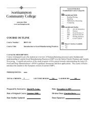
Activity 2: Scissors liftHave students work in groups of 2. Provide a scissor lift to each group.This activity is designed to demonstrate the use of hydraulic power <strong>and</strong> the differencebetween hydraulic <strong>and</strong> pneumatic power.Scissor Lifts are one of the most essential<strong>and</strong> often-used types of material h<strong>and</strong>lingequipment in the industrialized world. Somescissor lifts are built as small portable carts<strong>and</strong> designed to lift no more than a couplehundred pounds of material; others are builtto maintain a load of 50 tons. Scissor liftsare available to be operated by manualhydraulic foot pump, mechanical screw, <strong>and</strong>electric hydraulic, air hydraulic or air bag.The small scissor lift uses a similarmechanism that is used in real life. Ahydraulic piston (syringe) pushes one of thearms <strong>and</strong> with a first class lever the platformrises up horizontally. They are often used todo repairs to, or build ceilings where it ishigh, <strong>and</strong> a ladder won't do. As you can see,the platform can be a very stable workplace.Operating the lift1. Charge up the syringeTo charge (fill) the syringe push the 14 cm tube tightly over the end. Slowly suck waterup into it. Holding the syringe vertically, push the plunger <strong>and</strong> expel the air from thesyringe <strong>and</strong> the tube. You may have to suck up the water <strong>and</strong> push it out a few times toget all the air bubbles out. Gently tap the syringe while holding it vertically so thebubbles float up, <strong>and</strong> then push them out. When the syringe is fully charged with nobubbles in the tube, hold the piston attached to the block tightly closed so the plunger isfully in <strong>and</strong> then push the tube over the end as far up as you can.2. Operate the lift by pushing <strong>and</strong> pulling the syringe piston.Pneumatics <strong>and</strong> hydraulicsBoth pneumatics <strong>and</strong> hydraulics are applications of fluid power. Pneumatics uses air whilehydraulics uses oil or water. <strong>One</strong> of the main differences between the two systems is that inpneumatics, air is compressible. In hydraulics, liquids are not.Hydraulic Systemsa) Hydraulic systems use liquids such as oil <strong>and</strong> water to perform work processes.b) Hydraulic systems are closed systems, re-circulating the oil or water after use.Pneumatic Systemsa) Pneumatic systems use compressed gas such as air or nitrogen to perform workprocesses.b) Pneumatic systems are open systems, exhausting the compressed air to atmosphereafter use.<strong>Module</strong> 4 Student Guide <strong>Fluids</strong> & <strong>Thermodynamics</strong> Page 10
3. Switch the water filled syringe with an air filled syringe <strong>and</strong> operate the lift. Note thedifferences in force required when using the water filled syringe.Activity 3: The Mechanical Advantage of HydraulicsHave student work in groups of 2. Provide each group with the following:1 30ml syringe2 60ml syringeT connectorTubingPeg board with legsTie wraps100 gram weightWaterThe key advantage of using liquids over air is that they cannot be compressed. They aresaid to be 'incompressible'. If you fill a syringe with water <strong>and</strong> press the plunger by puttingyour thumb over the nozzle, it will not move. This is because the water in the syringecannot be compressed.The fact that liquids cannot be compressed is extremely useful. It means that pressure canbe transmitted through liquids.When you connect the two syringes together with the rubber tubing <strong>and</strong> then fill them withwater, you observe that pressing one plunger in makes the other one come out. In fact, youhave transmitted pressure from one plunger to the other. However, we do not know whatmechanical advantage was gained.With syringes of different sizes it is possible to demonstrate how tomultiply force. A small mass on a small syringe can lift a much largermass if it is resting on a bigger syringe.This is because the pressure in the two syringes is equal, but thesurface areas of the two pistons are different, <strong>and</strong> force = pressure ×area.1. Connect two syringes of different sizes together as shown inFigure 1.2. Place a 100g mass on the larger syringe (B) <strong>and</strong> determine howmuch force is required to push B up by placing different masseson syringe A. Use a box or peg board to hold the syringes.Also note the distance that plunger B is move up.The basic relationship of forces in a hydraulic system is:Force OUT = Force IN x Area B/Area AFigure 1For example, in Area A is one square inch <strong>and</strong> Area B is 10 square inches. Then the forceat B would be 10 times greater. If we place a 1 lb mass on A then we could lift 10 lbs at B.Force OUT = 1lb x 10in 2 /1in 2 or Force OUT = 1lb x 10 = 10lbs<strong>Module</strong> 4 Student Guide <strong>Fluids</strong> & <strong>Thermodynamics</strong> Page 11
3. Was there any mechanical advantage provided by the hydraulic system (syringes) in themini lift that you operated in Activity 1?<strong>Module</strong> 4 Student Guide <strong>Fluids</strong> & <strong>Thermodynamics</strong> Page 12
The key mechanical advantage of hydraulic systems is that the same pressure is applied toall areas within the container.Pascal’s LawPressure exerted on a confined liquid at rest is transmittedequally in all directions.It is the same at any point in the liquid, <strong>and</strong> acts at rightangles to the surfaces of the container.• Pascal’s law is valid irrespective of the shape of thevessel• Any change in the exerted pressure is seen almostinstantly throughout the liquid.If syringe A’s area is 1 in 2, <strong>and</strong> we apply a 1lb force then weare applying 1lb per square inch. That is we are applying 1 lbof pressure to every square inch in Syringe A, Syringe B<strong>and</strong> the tubing connecting the syringes.In Figure 1, the pressure is the same for all areas, so 1lb ofpressure is applied to each square inch.If the Area of B is 10 square inches then we have 10 timesthe force.Formally:Pressure = Force/Area or P =F/AFor 1lb of force applied to 1 square inch: P = 1lb/in 2 .This is usually referred to as psi(pressure per square inch)Figure 1<strong>Module</strong> 4 Student Guide <strong>Fluids</strong> & <strong>Thermodynamics</strong> Page 13
Activity 4: Demonstrating Equal Pressure in a Hydraulic SystemUse a T connector <strong>and</strong> create the hydraulic system shown below.1. Charge each of the syringes with water <strong>and</strong> connect the Syringes as shown above.2. Place a mass on B <strong>and</strong> then place a mass on A that will lift B3. Remove the mass placed on A but keep the mass on B. Then place the same mass thatis placed on B onto to Syringe C.4. Note what happens. The mass on A should lift the masses on C <strong>and</strong> B.5. Note how far C <strong>and</strong> B were lifted. Were they lifted the same distance as A was pusheddown?6. Take the mass off syringe A <strong>and</strong> push the plunger down two major marks (e.g. from the5ml mark to the 15ml mark). Note the distance that the pistons for syringes C <strong>and</strong> Bwere raised.As you may have noticed that you have to pay for the multiplied output force by exerting asmaller input force through a larger distance. That is because work (W) has to remainthe same. That is the amount of work applied to syringe A has to be equal to the amountof work applied to syringe B.Work is the amount of force applied to an object through a constant direction “x”:W = Force x Distance(x) or W = FxIf you apply 10 lb of force to an object for 10 feet you would apply 100 ft-lbs of work.If youThen(1) apply 10gm of force to Syringe A piston <strong>and</strong>(2) push it down 10 centimeters <strong>and</strong>(3) there is 100gm mass on Syringe B,(4) Syringe B will move a distance of 1 centimeter7. See if you can build a model of a brake system using syringes for the master cylinder,slave cylinder <strong>and</strong> 4 brake cylinders.<strong>Module</strong> 4 Student Guide <strong>Fluids</strong> & <strong>Thermodynamics</strong> Page 14
The brakes in cars are a good example of a basic piston-driven hydraulic system.Lines to each of the brakes on the four wheels are connected to the slave cylinder.1. Your foot pushes on the brake pedal.2. As the pedal moves down, it pushes aclass 2 lever increasing your pushingforce.3. The lever pushes a piston (blue) into anarrow cylinder filled with hydraulicbrake fluid (red). As the piston movesinto the cylinder, it squeezes hydraulicfluid out of the end (like a bicycle pumpsqueezes out air).4. The brake fluid squirts down a long, thinpipe until it reaches another cylinder atthe wheel, which is much wider.5. When the fluid enters the cylinder, itpushes the piston in the wider cylinder(blue) with greatly increased force.6. The piston pushes the brake pad (green)toward the brake disc (grey).7. When the brake pad touches the brakedisc, friction between the two generatesheat (red cloud).8. The friction slows down the outer wheel<strong>and</strong> tire, stopping the car.<strong>Module</strong> 4 Student Guide <strong>Fluids</strong> & <strong>Thermodynamics</strong> Page 15
You can determine the different values for Work, Force, Pressure, <strong>and</strong> Distance forhydraulics at HyperPhysics: http://hyperphysics.phy-astr.gsu.edu/hbase/pasc.html#hpressHyperPhysics Home Pagehttp://hyperphysics.phyastr.gsu.edu/hbase/hframe.htmlHydraulic Presshttp://hyperphysics.phyastr.gsu.edu/hbase/pasc.html#hpressClick on Calculation or Scroll downYou can enter values in either U.S. or metricdimensions:r: Radius of the pistonsA: Areas of the pistonsIt will calculate the force multiplicationThen enter values for the input force (F 1 )It will calculate the Pressure (P) <strong>and</strong> theoutput force (F 2 )Enter the distance for the output distance (d 2 )It will calculate the input distance (d 1 )Note if you scroll down the page, an explanationof the Automobile Hydraulic Lift if provided.<strong>Module</strong> 4 Student Guide <strong>Fluids</strong> & <strong>Thermodynamics</strong> Page 16
How does a Hydraulic Jack Work?Hydraulic jacks work on the basis of Pascal's Principle.Pressure is described mathematically by a Force divided by Area. Thereforeif you have two cylinders connected together, a small one <strong>and</strong> a large one,<strong>and</strong> apply a small Force to the small cylinder, this would result in a givenpressure. By Pascal's Principle, this pressure would be the same in thelarger cylinder, but since the larger cylinder has more area, the forceemitted by the second cylinder would be greater. This is represented byrearranging the pressure formula P = F/A, to F = PA. The pressure stayedthe same in the second cylinder, but Area was increased, resulting in alarger Force. The greater the differences in the areas of the cylinders, thegreater the potential force output of the big cylinder.A hydraulic jack is simply two cylinders connected as shown above.Assume a small piston (one squareinch area) applies a weight of 1 lb. toa confined hydraulic fluid.That provides a pressure of 1 lb. persquare inch throughout the fluid.If another larger piston with an areaof 10 square inches is in contact withthe fluid, that piston will feel a forceof 1 lbs/square inch x 10 squareinches = 10 lbs.So we can apply 1 lb. to the small piston <strong>and</strong> get 10 lbs. of force to lift a heavy object withthe large piston. Is this 'getting something for nothing'? Unfortunately, no. Just as a leverprovides more force near the fulcrum in exchange for more distance further away, thehydraulic lift merely converts work (force x distance) at the smaller piston for the SAMEwork at the larger one. In the example, when the smaller piston moves a distance of 10inches it displaces 10 cubic inches of fluid. The 10 cubic inches displaced at the 10 squareinch piston moves it only 1 inch, so a small force <strong>and</strong> larger distance has been exchangedfor a large force through a smaller distance.You will have to operate the h<strong>and</strong>le 10 times to lift the heavy object 10 inches.<strong>Module</strong> 4 Student Guide <strong>Fluids</strong> & <strong>Thermodynamics</strong> Page 17
Activity (Supplemental): Experiments with Pneumatic/Hydraulic Jack SetHave students work in groups of 2. Provide each group with the following:Hydraulic jack setSeveral text books to use as weightsThis activity uses a self-contained kit to conductseveral experiments involving fluids <strong>and</strong> air power.• The operation of a pump• The hydraulic/pneumatic jack as a forcetransformer (simple machine)• The difference in the ability of gases tocompress compared to liquids• Force, area, <strong>and</strong> the concept of pressure• Boyle's law, using air or other gasesSetting up the apparatus1. Connect the hose assemblies <strong>and</strong> associated partsin the order (d) - (e) - (f) - (g) - (h), as shown inFigure 1.The quick-connect fittings only require a fractionof a turn with light finger pressure. Do not overtighten.2. Install the 60 cc syringe (c) in the Jack st<strong>and</strong> (a),with the graduations visible from the front. Thenturn the syringe one-third turn counter-clockwise.3. Place the sidearm of the tee (e) up through thehole in the bottom of the st<strong>and</strong> (a) <strong>and</strong> onto theend of the syringe (c). Turn the syringe clockwiseone-third turn to connect the tee to the syringe.Do not over tighten.4. Insert the piston (b) into the syringe (c). Push itin all the way.5. Install the 6 cc syringe (k) onto the sidearm ofthe tee of part (d). Do not over tighten.(j-m) Smaller syringes (3 cc, 6 cc, 12cc, 20 cc)Figure 1(If the apparatus is to be used with air or other gases, setup is complete. If the unit is to beused with water as a hydraulic system, continue with the following steps.)6. Place the unattached ends of the tubing (d) <strong>and</strong> (h) in the bottom of a beaker or similarcontainer of water.a) The valve should be opened (on) with the h<strong>and</strong>le in line with tubing, as shown in thediagram.b) Pull out the small syringe to the limit of the measuring graduation marks. Push it allthe way in.c) Repeat this several times, watching the movement of the fluid <strong>and</strong> air bubbles. Make<strong>Module</strong> 4 Student Guide <strong>Fluids</strong> & <strong>Thermodynamics</strong> Page 18
sure the ends of the tubing do not come out of the water.Observing the Action of the Pump1. The valve (g) should be opened (on) with the h<strong>and</strong>le in line with the tubing, as shown inthe diagram. Pull out the small syringe to the limit of the measuring graduation marks.Push it all the way in. Repeat this several times, watching the movement of the fluid <strong>and</strong>air bubbles. Make sure the ends of the tubing do not come out of the water.Describe the fluid movement during the pull stroke.Describe the movement during the push stroke.2. Close the valve (g) by turning the h<strong>and</strong>le one-quarter turn, so that the h<strong>and</strong>le is at rightangles to the tubing. Pump the small syringe 3 or 4 times. Describe what happens, <strong>and</strong>tell why it happens.3. Without allowing the ends of the tubing to come out of the water, turn the main piston<strong>and</strong> cylinder assembly upside down. Open the valve, push in the main piston to expelany air, <strong>and</strong> close the valve. Return the main piston <strong>and</strong> cylinder assembly to its normalupright position. The process of eliminating air from a hydraulic system is referred to as"bleeding the system".The Hydraulic Jack as a Simple Machine, or "Force Transformer"Machines such as levers, pulley arrangements, <strong>and</strong> hydraulic systems can multiply an inputforce, to produce a greater output force. In this experiment we investigate this phenomenonin a hydraulic jack.1. Set up <strong>and</strong> "bleed" the apparatus as described previously. The large piston should bepushed all the way down. The 6 cc syringe should be installed as indicated in thediagram. Its piston should be pulled out to the largest volume graduation mark. Thevalve (g) should be closed (h<strong>and</strong>le at right angles to the tubing.)2. Make a stack of 4 to 6 textbooks, <strong>and</strong> find its weight in Newtons.3. Carefully balance the stack of textbooks on the platform of the large piston. Take care toposition them so that they are centered <strong>and</strong> do not lean in any direction.CAUTION! The load should not exceed 6 textbooks. To prevent breakage, do notpump the piston above the 40 cubic centimeter mark at any time during theexperiment. And to repeat, it is very important that the books be centered <strong>and</strong> notcause the piston to lean.4. Push in the piston of the small syringe <strong>and</strong> notice the amount of force required. Inwords, compare the force you used to the amount of force that would have beenrequired to lift the books directly.5. Compare the distance you moved the small piston to the distance the books were lifted.6. Pump the piston of the small syringe several times. Record your observations.<strong>Module</strong> 4 Student Guide <strong>Fluids</strong> & <strong>Thermodynamics</strong> Page 19
7. Open the valve by turning the h<strong>and</strong>le to line up with the tubing. What happens to theload of books?8. Summarize your observations: You lifted a heavy weight, overcoming a large force ofgravity, a short distance by using a (larger, smaller) ______ force over a (longer,shorter) _________ distance.9. Next you will make measurements to quantify these observations. Record yourmeasurements in the Table 1. Measure the distance the small piston moves as youmove it from a starting position at the largest graduation mark to the zero mark. Use aruler, not the graduations on the syringe. This is Distance in.10. Pull out the small piston to the largest graduation mark. Now measure the force requiredas you push in the piston. Use a force sensor if available. If not, use another method,such as holding the syringe vertical <strong>and</strong> piling on stackable lab weights. This result,expressed in Newtons is Force in . Record this measurement in Table 1.Table 1Syringe Force in Distance in Force out Distance out AMA IMA Work in Work out Efficiency6 ccForce in <strong>and</strong> Distance in are the force <strong>and</strong> distance involved in operating the small syringe.Force out is the weight of the stack of books, <strong>and</strong> Distance out is the distance they were liftedas a result of one stroke of the small piston.Calculating Work is described in Activity 4.See Mechanics <strong>Module</strong>:AMA (actual mechanical advantage),IMA (ideal mechanical advantage),Efficiency11. Open the valve to lower the load. Then close the valve again.Note the position of the large piston that supports the books.12. Pump the small piston for 5 strokes. Count the strokes, <strong>and</strong> use a ruler to measure thedistance the piston moved. Also note the volume of fluid that entered the syringe. Dividethe distance by the number of strokes to find the distance out for 1 stroke13. Repeat the above measurements for some or all of the other small syringes.14. Find the AMA, IMA, Work in , <strong>and</strong> Workout <strong>and</strong> record your results in Table 1.15. Is the efficiency different for different systems?<strong>Module</strong> 4 Student Guide <strong>Fluids</strong> & <strong>Thermodynamics</strong> Page 20
Relating Force, Area, <strong>and</strong> PressureThis experiment is a study of how the variables force, area, <strong>and</strong> pressure are related.In this experiment we will produce the same amount of pressure four different times byapplying force to four different syringe pistons. The amount of pressure created will be justthe amount needed to lift a stack of books on the hydraulic jack, <strong>and</strong> is thus the same eachtime. Each small piston has a different cross-sectional area, <strong>and</strong> requires a different force toproduce the required pressure.The force, area, <strong>and</strong> pressure are related by a simple formula that may be discovered usingthis apparatus.1. Set up <strong>and</strong> bleed the system as described previously.2. Carefully balance several large books on the platform of the large piston. Take care toposition the books so that they do not lean in any direction.Caution! To prevent breakage, do not pump the piston above the 40 cubic centimeter markat any time during the experiment3. If a pressure sensor is available, connect it to the sidearm of part (i), which is connectedbetween parts (f) <strong>and</strong> (g), as shown in the Figure 1.4. With the smallest piston installed on the sidearm of the tee in part (d), measure theforce required to push in the plunger <strong>and</strong> lift the stack of books. Use a force sensor ifavailable. If not, use another method such as holding the syringe vertical <strong>and</strong> piling onstackable lab weights. Express the force in Newtons.5. Find the cross-sectional area of the small syringe. This may be done by measuring theinside diameter of the syringe, <strong>and</strong> using the formula for the area of a circle. A moreaccurate method is to use a ruler to measure the graduated portion of the syringe, <strong>and</strong>to note the volume of that portion. A formula for the volume of a cylinder, allowscalculation of the area.Volume = Area x Length6. Convert the area to square meters7. Record the pressure if a pressure sensor is available.8. Repeat the above steps for all four small syringes.9. Make a graph displaying the (area, force) data pairs from the four small syringes. Areashould be plotted along the horizontal axis, <strong>and</strong> force along the vertical axis.A straight line passing through the origin should show the pattern of the data. Usetechnology or traditional techniques to determine the equation of this best-fit line.The slope of the line is constant, <strong>and</strong> the pressure was also constant in this experiment.It seems plausible that these two facts are related. In fact, the slope is Force / Area,which is the definition of pressure.10. If a pressure sensor was available during this experiment, compare the pressure to theslope, <strong>and</strong> comment. (If the pressure sensor is calibrated in units of Pascals, (Pa), notethat one Pascal is the same as one Newton per square Meter.)<strong>Module</strong> 4 Student Guide <strong>Fluids</strong> & <strong>Thermodynamics</strong> Page 21
11. Calculate the pressure by considering the weight of the books, <strong>and</strong> the area of the pistonsupporting them. Make the necessary measurements, <strong>and</strong> calculate the pressure inNewtons / square meter.12. Calculate the pressure by considering the weight of the books, <strong>and</strong> the area of the pistonsupporting them. Make the necessary measurements, <strong>and</strong> calculate the pressure inNewtons / square meter.13. Compare the pressure just calculated to the slope of the graph <strong>and</strong> comment.Boyles Law (Optional)Unlike liquids, which have a relatively constant volume, a sample of gas may vary greatly involume. The volume <strong>and</strong> pressure are related by a mathematical formula called Boyle's Law.This lab provides data that may be analyzed to discover this formula. Air or another gasmay be used as the gas.1. Set up the system as described previously, except that the system should be as free ofwater as possible. Attach any small syringe to the sidearm of the tee of part (s). Ifpossible, arrange to use a pressure sensor. The sensor will be attached to the sidearm ofpart (i). Part (i) is then installed between parts (f) <strong>and</strong> (g).2. If a pressure sensor is not being used, lubricating the large syringe is important. Useglycerin or silicone oil. Do NOT use a petroleum based lubricant, because doing so willrapidly ruin the seals.3. Close valve (g) by turning the h<strong>and</strong>le at right angles to the tubing. If a gas other thanair is to be used, connect a balloon containing the gas to the unattached end of hoseassembly (d). If air is to be used, leave the end unattached. Now pump the smallsyringe until the large syringe piston goes up to the 20 cc mark. Open the valve whilepushing the large syringe platform down, <strong>and</strong> then close the valve again. Use the smallsyringe to pump the large syringe piston up to the 50 cc mark.4. If a pressure sensor is attached, add one book at a time to the platform at a time,carefully balancing the stack each time. Use a maximum of six books. Record thepressure <strong>and</strong> corresponding volume each time. If a pressure sensor is being used thatmeasures absolute pressure, then these readings should be recorded under "totalpressure" in the table, <strong>and</strong> the column "pressure due to books" may be left blank. If thepressure sensor measures "gauge pressure", then the readings should be recordedunder "pressure due to books". Then the total pressure may be calculated by adding 101KPa (a typical barometric pressure at sea level), or, better, actual barometric pressureat your location. The column for total weight of books may be left blank if a pressuresensor is being used.5. If working without a pressure sensor, add identical books one at a time, recording thevolume after each book has been added. The total weight of books should be expressedin Newtons.6. To calculate the pressure due to the books when a pressure sensor is not available, itwill be necessary to calculate the cross-sectional area of the large syringe. This may bedone by measuring the inside diameter of the syringe, <strong>and</strong> using the formula for thearea of a circle.<strong>Module</strong> 4 Student Guide <strong>Fluids</strong> & <strong>Thermodynamics</strong> Page 22
A more accurate method is to use a ruler to measure the graduated portion of thesyringe, <strong>and</strong> to note the volume of that portion. A formula for the volume of a cylinder,Volume = Area x Lengthmay be solved for area, allowing calculation of the area. Convert the area to squaremeters. Then divide the weight of the books in Newtons by the area of the syringe insquare meters. The answer is in units of Newtons per square meter, or Pascals (Pa). Toobtain KPa, divide by 1000. Then the total pressure may be calculated by adding 101 KPa(a typical barometric pressure at sea level), or, better, actual barometric pressure atyour location7. If a pressure sensor was available during this experiment, compare the pressure to theslope, <strong>and</strong> comment. (If the pressure sensor is calibrated in units of Pascals, (Pa), notethat one Pascal is the same as one Newton per square Meter.)8. Calculate the pressure by considering the weight of the books <strong>and</strong> the area of the pistonsupporting them. Make the necessary measurements, <strong>and</strong> calculate the pressure inNewtons/square meter.9. Compare the pressure just calculated to the slope of the graph <strong>and</strong> comment.# ofbooksVolumeTotal wtof booksPressure dueto booksTotalPressure123456Boyle's Law states that the Pressure of a gas sample times its Volume is constant, assumingconstant temperature. Test this by calculating P x V for the gas sample for each of the 6pressures.<strong>Module</strong> 4 Student Guide <strong>Fluids</strong> & <strong>Thermodynamics</strong> Page 23
Lesson 5: How Heat FlowsText <strong>and</strong> Activities are from NeoSci How Heat Flows programEarly scientists believed that heat was an invisible, weightless fluid capable of flowing fromhotter objects to colder ones. They called this fluid substance "caloric."It was not until 1798 that scientists finally got on the right track in explaining the truenature of heat. Benjamin Thompson, who became known as Count Rumford, was anAmerican who went to Bavaria to help in the boring of cannon barrels. He observed that thecannon <strong>and</strong> the boring tools became hot as the drilling progressed <strong>and</strong> that, even when theboring tools became dull <strong>and</strong> little material was being removed, heat continued to begenerated. Thus, he concluded that the heat generated was related to the work done <strong>and</strong>was, in fact, just another form of energy.Forty years after Count Rumford's observations, a British scientist named James PrescottJoule performed a series of experiments that supported the relationship between heat <strong>and</strong>motion. Combining all of the facts known about heat, we currently use the followingdefinitions: thermal energy is the energy associated with the internal motion of molecules inmatter <strong>and</strong> heat is thermal energy in transfer.Thermal energy is transferred in three ways:ConductionConvectionRadiationThermal energy is transferred from one substance to another by directcontact.Transfer of thermal energy that takes place in liquids <strong>and</strong> gasesTransfer of thermal energy that takes place through space, includingthrough vacuum, such as in the case of energy transfer from the sunHeat <strong>and</strong> TemperatureA misconception held by many people is that temperature <strong>and</strong> heat are the same. Althoughtemperature <strong>and</strong> heat are related, they are not the same. Heat is thermal energy intransfer, <strong>and</strong> temperature is the measure of this form of energy. The old terms from calorictheory still remain, <strong>and</strong> a common unit of measure for heat is the "calorie." The calorie isdefined as the amount of energy that must be added to one gram of water to make itstemperature increase by one degree Celsius, from 14.5°C to 15.5°C.Heat is in fact molecular vibrations in any substance. The hotter something is, the more themolecules in that substance vibrate. Temperature is a measurement of these tiny vibrations.The more vigorous the vibrations, the higher the temperature.Matter can exist in three phases: solid, liquid <strong>and</strong> gas. A phase change - such as solid toliquid or liquid to gas requires heat. The amount of heat needed to change 1 gram of asubstance from a solid phase to the liquid phase is known as the "heat effusion." Theamount of heat needed to change 1 gram of a substance from a liquid phase to a gas phaseis called "heat of vaporization."Solids, gases <strong>and</strong> liquids exp<strong>and</strong> when heated. When solids are heated, molecules movefarther away from their fixed position <strong>and</strong> from each other. This increased distance amongthe molecules accounts for the expansion of solids. Liquids also exp<strong>and</strong> as they are heated.An exception to this rule is water which, between the temperature of 4 °C <strong>and</strong> 0 °C,exp<strong>and</strong>s as it cools. Thermal expansion in gases is due to molecules moving faster <strong>and</strong>faster as the temperature increases.<strong>Module</strong> 4 Student Guide <strong>Fluids</strong> & <strong>Thermodynamics</strong> Page 24
Activity 1: Thermal Conductivity of Different MetalsThermal energy transfer occurs between twosubstances whenever there is a temperaturedifference between them. The process of thermalenergy transfer from one substance to anotherby direct contact is known as "conduction."During this process, thermal energy istransferred from a warmer substance to a coolerone. Thermal energy transfer is dependent onthe conductivity of the substance. Thermalconductivity is a measure of how fast thermalenergy moves within a substance. The thermalconductivity unit of measurement (k) is Joulesper meter second per degree Celsius (J/ms °C).Data Table 3 lists the thermal conductivity ofselect substances. Diamond has the highestthermal conductivity valueData Table 3Substance Thermal Conductivity(J/ms °C)Diamond 2,450.0Copper 385.0Aluminum 237.0Brass 110.0Nickel 90.7Iron 80.2Steel 50.2Ice 1.60Glass 1.28Water, distilled 0.61Wood 0.1Air 0.024Safety: Wear heat protective gloves <strong>and</strong> safety goggles. An open flame is required duringthis activity so extra vigilance is required. The instrument is very hot during use <strong>and</strong> cancause serious injury. Do not touch any metal part of the instrument during the experiment.Do not allow the instrument to overheat or the wax may smoke.Have students work in groups of 2. Provide each group with the following:Heat conductometerC<strong>and</strong>leC<strong>and</strong>le lighter1. Examine the apparatus to be certain that you underst<strong>and</strong>its operation. The heat conductometer is madeup of five different metals - aluminum, brass, steel,stainless steel, <strong>and</strong> copper radiating from a hexagonalbrass hub. At the end of each arm, there is a notch tohold wax.2. Hold the heat conductometer horizontally, with the notches facing upwards. Pack eachnotch with wax. The wax should be level with the top of the notch. Make sure that thenotches are equally full.3. Hold the center solid part of the conductometer over a c<strong>and</strong>le flame <strong>and</strong> carefullyobserve what happens. Be sure that the conductometer is heated slowly. Record theorder in which the wax melts in the 4 notches.4. Douse the c<strong>and</strong>le flame <strong>and</strong> place the conductometer out of reach. Allow it to cool downbefore another student group uses it. Do not touch the instrument. If the instrumentbegins to smoke, immediately douse the flame <strong>and</strong> end the experiment.5. Rank the metals in order of thermal conductivity.<strong>Module</strong> 4 Student Guide <strong>Fluids</strong> & <strong>Thermodynamics</strong> Page 25
Activity 2: Thermal ExpansionSAFETY: Wear heat protective gloves <strong>and</strong> safety goggles. An open flame is required duringthis activity so extra vigilance is required. The instrument is very hot during use <strong>and</strong> cancause serious injury. Do not touch any metal part of the instrument during the experiment.Heat the instrument in a fume hood, if possible.This is experiment requires a very large heat source. Perform this as a demonstration. A propane torchwill be require to heat the ball to a sufficient temperature1. Obtain a metal ball <strong>and</strong> ring apparatus. Pass the ball through the ring. Does it passthrough the ring easily?2. Heat the ball for about 30 seconds.3. Try to pass the ball through the ring again. If the ball passes through, reheat the ball foran additional 30 seconds. Record your observations. Were you able to pass the ballthrough the ring?NOTE: Continue to heat the ball at 30 second intervals until it will not pass through thering.4. Immediately heat the ring <strong>and</strong> try to pass the ball through it. Record your observations.5. What is meant by thermal expansion?Activity 3: Radiant Heat <strong>and</strong> EnergyIn the following activity, you will use a radiometer to explore radiant heat <strong>and</strong> energy. Thevanes, or wings, of the radiometer are alternately black <strong>and</strong> white in color. When lightstrikes these vanes, it transfers heat to each of them, but not equally. The white vanesreflect the heat, while the dark vanes absorb the heat. Because of this difference, the vanesbegin to spin. The more thermal energy there is to heat up the dark vanes, the faster theyspin.1. Place the radiometer on your lab bench <strong>and</strong> observe any movement of the vanes.2. Place your h<strong>and</strong>s around the radiometer <strong>and</strong> observe the vanes from the top. Are thevanes spinning?3. As an option, use a lamp to compare the speed of the vanes as more energy istransferred to them. Place the lamp about 6 inches over the radiometer <strong>and</strong> turn it "on."Observe what is happening to the vanes. Are the vanes moving any faster<strong>Module</strong> 4 Student Guide <strong>Fluids</strong> & <strong>Thermodynamics</strong> Page 26
4. What is radiant heat?5. List three ways that thermal energy is transferred.Activity 4: Calibration of a ThermometerHave students working groups of 2. Provide each group with the following:Unmarked thermometerCalibrated thermometerPyrex beakerHot plateRed sharpie markerWaterIceTemperature scales were originally based on two fixed temperatures, the freezing point <strong>and</strong>the boiling point of watt;-" Unfortunately different scientists arbitrarily assigned differentnumbers to the boiling point <strong>and</strong> the freezing point of water. Because of this historicalchoice the boiling point was set at 212 degrees on the Fahrenheit scale <strong>and</strong> 100 degrees onthe Celsius scale while the freezing point was set at 32 degrees on the Fahrenheit scale <strong>and</strong>0 degrees on the Celsius scale. Thus, there are 180 Fahrenheit degrees <strong>and</strong> 100 Celsiusdegrees between the freezing point <strong>and</strong> the boiling point of water. This means that theFahrenheit degree must be smaller than the Celsius degree. In fact, each Fahrenheit degreeis only 5/9 as big as a Celsius degree. Since the Celsius scale begins at zero <strong>and</strong> theFahrenheit scale at 32, to convert from one scale to the other the following formulas can beused:°F = (9/5)°C + 32°C = (°F - 32) x 5/9Create your own Celsius Scale Thermometer1. Fill a beaker with ice water <strong>and</strong> place an unmarked thermometer in it2. Allow the thermometer to remain in the ice water for several minutes, until the red liquidinside it stops moving. Using a wax pencil or permanent marker, mark the lowest pointreached by the red liquid in the thermometer. This point is the freezing temperature orzero degree point on the Celsius scale.Safety: Wear safety goggles, apron, <strong>and</strong> heat protective gloves. Do not touch hotobjects with your bare h<strong>and</strong>s. Scalding water can cause severe burns. Proceed withextreme caution.3. Place the beaker on a hot plate <strong>and</strong> begin heating it. Continue heating the water untilthe red liquid reaches its highest point. This temperature is 100 °C. What is happeningto the water at this point?Note: As an added safety precaution, you may heat the water up to 50 °C. You'll need touse a calibrated thermometer to know when the water reaches this temperature4. Using tongs or heat protective gloves, remove the thermometer from the hot water <strong>and</strong>allow it to cool before proceeding to the next step. Be sure to turn "off" the hot plate.5. Using a ruler, divide the distance between the lowest <strong>and</strong> highest recorded points intoten equal parts, if the water were allowed to boil, or into five equal parts if the watertemperature only reached 50 °C.6. Use your calibrated thermometer to determine the temperature of various liquids of yourchoice or even the room temperature.<strong>Module</strong> 4 Student Guide <strong>Fluids</strong> & <strong>Thermodynamics</strong> Page 27
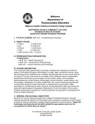
7. What property of matter is utilized by the red alcohol contained in the thermometer thatmakes it possible to measure temperature changes?8. Why were the freezing <strong>and</strong> boiling points chosen as the fixed points for establishingtemperature scales?9. Using the conversion formulas, find the Fahrenheit temperature corresponding to 20 °C,40 °C <strong>and</strong> 0 °C. Find the Celsius equivalent corresponding to 90 °F, 0 °F <strong>and</strong> 62 °F.How does a Heat Sink Work?( www.overclock.net/faqs/115016-info-how-does-heatsink-work.html)A heat sink (or heatsink) absorbs <strong>and</strong>dissipates heat from another object usingthermal contact (either direct or radiant).Heat sinks are used in a wide range ofapplications wherever efficient heatdissipation is required; major examplesinclude refrigeration <strong>and</strong> coolingelectronic devices.A "sink" is also a concept in science: ifyou want to say that there is a drain or away out for something, you might call it a"sink." You might have a sink forelectrons or a sink for heat.How it WorksUnderst<strong>and</strong>ing what heat isComputer CPU Heat Sink with Fan <strong>and</strong> smallerheat sink.Heat is in fact molecular vibrations in any substance. The hotter something is, the more themolecules in that substance vibrate. Temperature is a measurement of these tiny vibrations.The more vigorous the vibrations, the higher the temperature.How heat is transferredHeat is transferred because when a particle vibrates, it stimulates the particles beside it tovibrate. Think of this as holding a piece of rope at one end <strong>and</strong> shaking it. If you wave it inthe air, the rope will likely move all over. If the rope is on the ground, it will likely move alot less. Think of this as an example of particles stimulating neighboring particles, which isheat transfer, <strong>and</strong> also as an example of thermal resistance, which is what makes somematerials good at conducting heat, such as copper, <strong>and</strong> some materials bad at conductingheat, such as plastic.Thermally bonding the Heatsink <strong>and</strong> ComponentNow we know the basics of heat transfer, <strong>and</strong> thermal resistance, how can we translate thisinto how a heatsink works?<strong>Module</strong> 4 Student Guide <strong>Fluids</strong> & <strong>Thermodynamics</strong> Page 28
Well lets overview the set up so far. We have a CPU or other heat generating component,<strong>and</strong> a block of metal with low thermal resistance. The problem now is how do we efficientlytransfer this heat from the component to the heat sink?The answer is thermal compound, or Thermal Interface Material (TIM). This is usually apaste like substance with VERY low thermal resistance, <strong>and</strong> is usually made with particles ofsilver. Silver has very low thermal resistance, hence why it is used in TIM's. Also, TIM isdesigned as a paste so that it fills in the microscopic imperfections (Or valleys) on thesurface of the CPU <strong>and</strong> heatsink so that the entire surface of the CPU is thermally bonded(linked to in a way which allows heat to be transferred) to the base of the heatsink.Our setup is almost complete. We have a Heat source (Component of some sort), the TIM,<strong>and</strong> the Heatsink. The dissipation (moving <strong>and</strong> removal) of heat from the component cannow begin. The particles in the component vibrate, causing the particles in the TIM tovibrate. This in turn causes the particles in the heatsink to vibrate.But how does that make the CPU cooler? If more particles are vibrating, surely that meansthe component gets hotter?Every time a vibrating particle causes a neighboring particle to vibrate, it transfers energy.We know that energy cannot be created from nothing, <strong>and</strong> in the case of a heatsink, theenergy is generated from the power (Voltage <strong>and</strong> Current) being supplied to the componentbeing cooled. When this energy is transferred, the particle causes its neighboring particle tovibrate <strong>and</strong> lose energy. It vibrates less. In fact, this occurs to the point where the particlevibrates near enough as much as it neighboring particle.Within this theory lie the fundamentals to the Heatsinks operation. By spreading the heatacross a large piece of material, we can reduce the temperature of the component.Optimizing the heatsinks designSo we have a block of let’s say copper thermally bonded to a heat producing component.How can we increase the efficiency of this block? Well for a while the block will workreasonably well but there is a problem. Heat is only being spread across the materials.Think of this example. You are buttering a slice of toast. Think of the butter as heat, theknife as the component, producing the heat, <strong>and</strong> the toast as our copper block. We continuespreading butter onto the toast, so what happens? More <strong>and</strong> more butter (heat)accumulates on the toast (copper). This is a problem as the component is now going to gethotter <strong>and</strong> hotter because the copper is heating up with the component.To get rid of this heat of our material, we introduce a way of transferring this heat awayfrom the heatsink. It may be air, or water, or some other substance such as liquid nitrogen.For the sake of argument, we'll look at the most common medium for this application, air.So our job now is to transfer as much heat as possible from the copper to the surroundingair. How do we go about this? Well we know that a larger surface area being cooled is betterso we can turn the copper block into a block with fins to increase the heatsinks contact withthe air surrounding the heatsink.How the heat in the air (or other medium) is moved away from the heatsinkThankfully, physics is on our side in this. As most of you will know, hot air is less dense thancold air, because the vibrating particles cause themselves to be spaced further apart(Because they essentially push their neighboring particles away from them). Because ofthis, the hot air around or copper fins rises up <strong>and</strong> away from the heatsink (EG, a hot airballoon. The balloon is filled with hot air, <strong>and</strong> the balloon rises.) Due to air pressure, cold airfrom underneath is sucked up into the heatsink. Of course you won't actually notice this, as<strong>Module</strong> 4 Student Guide <strong>Fluids</strong> & <strong>Thermodynamics</strong> Page 29
it is nowhere near the type of suction you would get from something like a FAN. This bringsus onto or next point:Increasing the flow of air to the heatsinkQuite simply, mount a fan onto our copper fins to push more air across the heatsink. Thismeans that more heat can be dissipated from the heatsink <strong>and</strong> transferred into the air. Thishot air then rises, <strong>and</strong> is usually sucked out of your case via an exhaust fan at the back ofyour case.So there you have it. Heatsinks today also implement heatpipes, which are hollow copperpipes filled with a liquid which evaporates <strong>and</strong> condenses to transfer heat.<strong>Module</strong> 4 Student Guide <strong>Fluids</strong> & <strong>Thermodynamics</strong> Page 30
OnLine ResourcesHyperPhysicsHome Page: http://hyperphysics.phy-astr.gsu.edu/hbase/hframe.htmlHydraulic Press: http://hyperphysics.phy-astr.gsu.edu/hbase/pasc.html#hpressVCATS eLearninghttps://vcats.prosperitylms.com/req/vcats_student/index.cfmSelect: My ProgramsSelect: Fluid Power & <strong>Thermodynamics</strong>Heat Transfer <strong>and</strong> Phase ChangesThermo101-Heat TransferTrmoGiz101Heat Transfer by ConductionTrmoGiz102-Conduction & ConvectionTrmoGiz103-Phases of WaterTrmoGiz104-Phase ChangesRelationship between Pressure, Temperature & VolumeThermo201-Pressure, temperature & VolumeTrmoGiz201-Boyle’s Law <strong>and</strong> Charles’ LawTrmoGiz202-Temperature <strong>and</strong> Particle MotionHydraulics & PneumaticsThermo301-HydraulicsThermo302-PneumataicsPhET Simulationshttp://phet.colorado.edu/simulations/index.php?cat=Heat_<strong>and</strong>_ThermoStates of MatterFrictionGas PropertiesBalloons & Buoyancy<strong>Module</strong> 4 Student Guide <strong>Fluids</strong> & <strong>Thermodynamics</strong> Page 31