Triple BEAST - Benezan Electronics
Triple BEAST - Benezan Electronics
Triple BEAST - Benezan Electronics

You also want an ePaper? Increase the reach of your titles
YUMPU automatically turns print PDFs into web optimized ePapers that Google loves.
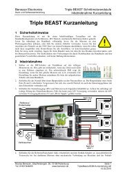
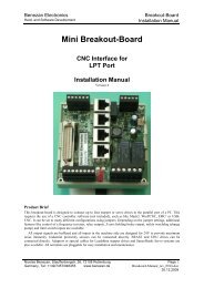
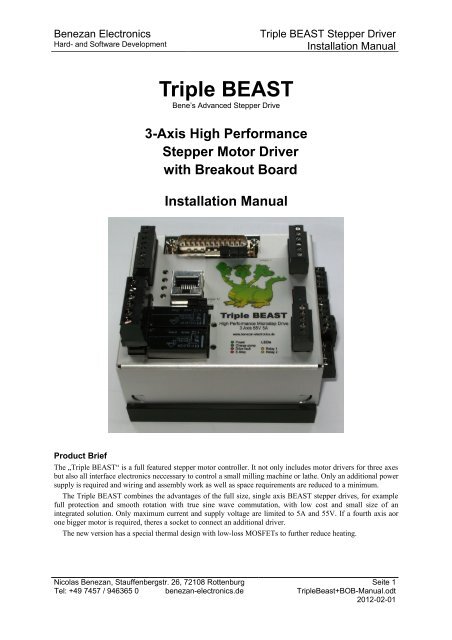
<strong>Benezan</strong> <strong>Electronics</strong>Hard- and Software Development<strong>Triple</strong> <strong>BEAST</strong> Stepper DriverInstallation Manual<strong>Triple</strong> <strong>BEAST</strong>Bene’s Advanced Stepper Drive3-Axis High PerformanceStepper Motor Driverwith Breakout BoardInstallation ManualProduct BriefThe „<strong>Triple</strong> <strong>BEAST</strong>“ is a full featured stepper motor controller. It not only includes motor drivers for three axesbut also all interface electronics neccessary to control a small milling machine or lathe. Only an additional powersupply is required and wiring and assembly work as well as space requirements are reduced to a minimum.The <strong>Triple</strong> <strong>BEAST</strong> combines the advantages of the full size, single axis <strong>BEAST</strong> stepper drives, for examplefull protection and smooth rotation with true sine wave commutation, with low cost and small size of anintegrated solution. Only maximum current and supply voltage are limited to 5A and 55V. If a fourth axis aorone bigger motor is required, theres a socket to connect an additional driver.The new version has a special thermal design with low-loss MOSFETs to further reduce heating.Nicolas <strong>Benezan</strong>, Stauffenbergstr. 26, 72108 RottenburgTel: +49 7457 / 946365 0 benezan-electronics.deSeite 1<strong>Triple</strong>Beast+BOB-Manual.odt2012-02-01
<strong>Benezan</strong> <strong>Electronics</strong>Hard- and Software Development<strong>Triple</strong> <strong>BEAST</strong> Stepper DriverInstallation Manual1 Safety InstructionsThe installation of the <strong>Triple</strong> <strong>BEAST</strong> has to be carried out by qualified personel, only. Please read this manualthoroughly and carefuly obey all instructions. Failure to do so can result in damage to mechanics, electronics orin personal injury.Depending on the level of risk of the machine it may be required to install additionalprotection devices like door locks or safe halt guards. All safety circuits must be implementedpurely electromechanical or with certified electronic parts that are not included in the <strong>Triple</strong><strong>BEAST</strong>. Relying on software or not certified electronic devices for critical safety functions isstrongly disencouraged. The machine manufacturer who carries out the final assembly and theoperator of the machine is responsible to meet all applicable safety standards and laws.Caution! Use an isolated power supply, only. Be sure to operate the <strong>Triple</strong>Beast within the maximumratings given in the technical data section. Make a protective ground connection to the machine frame andelectrical cabinet. The connection to the mains line requires special knowledge of the obligatory safetyprecautions. If you don't have the required qualification please let a professional electrician do this job foryou. For the first test run, remove the motor couplings or drive belts to avoid damage or injury due tounexpected movements.2 System requirementsFor a complete CNC drive system you need the following components additionally to the <strong>Triple</strong> <strong>BEAST</strong>controller:1. one to three stepper motors with two phase windings. Nominal motor current can be between 1.4 to 5A(up to 6A with restrictions). Three or five phase motors or smaller motors with high winding resistance fromprinters or disk drives are not suitable.2. A power supply with DC voltage between 24 and 55V. Voltage regulation is not necessary. See chapter3.3 for detailed requirements.3. A source for step and direction signals. This can be a PC with CNC software and LPT port or an externalsignal generator like a smoothstepper, for example.2.1 Recommended MotorsThe following table shows some motors that are recommended to be used together with the <strong>Triple</strong> <strong>BEAST</strong>. Themotor size should be choosen according to the requirements of the application. If you need assistance forcalculating motor sizes feel free to contact <strong>Benezan</strong> Electonics.Motor Typ Abmessungen Phasenstrom Betriebsspannung AnwendungHS56-0818 56 x 56mm 1,8A 24..48V pick&place machines, pen or knife plottersHS56-1442 56 x 76mm 4,2A 24..48VHS60-2150 60 x 90mm 5,0A 48..55Vsmall to medium sized milling orengraving machinesHS86-3263 86 x 78mm 5,0A 48..55V bigger milling machines for metal work,plasma cuttersThe <strong>Triple</strong>Beast also works with many types of motors from different brands. If possible, use modern hybridsteppers with neodymium magnets that are designed for microstepping. Best results are achieved with motorsizes from NEMA23 to 24 (56 to 60mm) and phase currents from 3 to 5A. Bigger motors (NEMA 34) can alsobe used but with some restrictions at speed and torque. Motors with high inductance (especially NEMA34 with4A or less) do generally not run very well at speeds above 500/min.If you need both high speed and hih torque you might consider using a single axis <strong>BEAST</strong> or Big <strong>BEAST</strong>driver instead which allows for a higher supply voltage and higher phase currents. A <strong>BEAST</strong> driver can be usedtogether with the <strong>Triple</strong>Beast as fourth axis.Nicolas <strong>Benezan</strong>, Stauffenbergstr. 26, 72108 RottenburgTel: +49 7457 / 946365 0 benezan-electronics.deSeite 2<strong>Triple</strong>Beast+BOB-Manual.odt2012-02-01
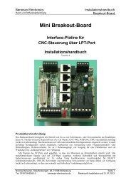
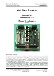
<strong>Benezan</strong> <strong>Electronics</strong>Hard- and Software Development<strong>Triple</strong> <strong>BEAST</strong> Stepper DriverInstallation Manual3 Setup and Connections3.1 Terminals overviewAll terminals are numbered from top tobottom (see picture to the right).Limit/home switch inputs(8-way terminal X3, top left)No Description1 Switch or sensor power supply (+12 or +24V)2 X axis switch or sensor input3 Switch or sensor power supply (+12 or +24V)4 Y axis switch or sensor input5 Switch or sensor power supply (+12 or +24V)6 Z axis switch or sensor input7 Switch or sensor power supply (+12 or +24V)8 4th axis switch or sensor inputRelay outputs(6-way terminal X4, bottom left)No Description1 230V~ L line input2 230V~ N line input3 Relay 1 L load output4 Relay 1 N load output5 Relay 2 L load output6 Relay 2 N load outputPower Supply motors(2-way terminal V, right side)No Description1 Motorspannung Eingang(+24..+55V)2 Masse 0VAuxilliary signals(6-way terminal X2, top right))No Description1 Ground for holding brake2 Holding brake output3 Analogue ground 0V4 Analogue output 0..10V5 E-Stop switch input6 E-Stop switch +12V outputPower Supply interface(5-way terminal X1, bottom right))No Description1 5V Output (max. 150mA)2 Ground 0V3 12V Output (max. 0.3A)4 Ground 0V5 24V Input (15..55V, max. 0.5A)Motor outputs(4-way terminal M1 to M3, right side)No Description12winding 134winding 2Nicolas <strong>Benezan</strong>, Stauffenbergstr. 26, 72108 RottenburgTel: +49 7457 / 946365 0 benezan-electronics.deSeite 3<strong>Triple</strong>Beast+BOB-Manual.odt2012-02-01
<strong>Benezan</strong> <strong>Electronics</strong>Hard- and Software Development<strong>Triple</strong> <strong>BEAST</strong> Stepper DriverInstallation Manual3.2 MountingThe drive is is supposed to be mounted on a DIN rail inside a closed cabinet. It is important to protect it fromchips, dust and coolant fluid. In the case of damage due to metal chips or humidity the warranty will be void.To fix the drive on a DIN rail hold it with the motor terminals upwards, hang in the hook at the rear side ofthe heatsink and firmly press onto the bottom until the clip is engaged. Alternatively, you can mount the heatsinkon a panel with self-tapping screws (B3.5 x 10mm). If you remove and re-assemble the rail clip, make sure not touse screws longer than 16mm. Otherwise the internal circuit boards or components could be damaged.Depending on the motor current the driver heats up more or les during operation. For this reason you shouldobey the following rules:• Leave at leas 2cm (3/4“) of free space between the <strong>Triple</strong> beast and other devices, cable ducts or cabinetwalls. Allow free air circulation around the driver.• If possible, install the heatsink with the fins aligned vertically• For motor currents up to 3 x 4.2A natural convection cooling is usually sufficient if there is enogh spacefor air circulation• If the sum of all motor currents exceeds 13A it is recommended to use forced convection cooling. A smallfan as used for PC CPUs is sufficient. You can connect it to the 12V output at pins 2+3 of terminal X1(300mA max.).Overheating does not destroy the <strong>Triple</strong>Beast because there's a thermal protection that shuts down the powerstage. However, it is recommended not to operate the device near the maximum temperature for too long becauseit could shorten the lifetime.3.3 Power SupplyThe supply voltage can be anything between 24 and 55V DC. For most applications, a switch mode supplywith 48V is perfectly suited because they are relatively cheap, small and lightweight. Furthermore they are shortcircuit proof and inrush current limiter and EMI filter is already included. However, it is not absolutely necessaryto use a regulated supply. A conventional transformer, rectifier and electrolytic capacitor would also do. In thiscase, please plan for some headroom as voltage can rise or fall by 10% or more due to load and line fluctuations.Make also sure to install proper fuses, inrush limiter and filters if necessary.The theoretical maximum current draw from the supply is 2/3 times the sum of all motor currents. The actualaverage current consumption is much lower in most of the cases. For example, to operate three motors of 4Aeach a supply capable of sourcing 8A peak and 5A average current is sufficient. If the load inertia is much higherthan that of the motors it is recomended to connect a bypass capacitor of at least 4700µF in parallel to the DCsupply to buffer returned braking energy (back EMF) caused by rapid decellerationConnect the positive output of the power supply to the terminal V.1 marked „+24..55V“ at the right side (seepicture above). Connect the negative output to V.2 marked „GND“. Caution, reverse polarity can damage thedriver, especially if the supply is not fused or current limited properly. Do not connect or disconnect thesupply while it is powered. Do not switch the DC side of the supply, this causes excessive arcing. Alwaysswitch the primary (AC) side of the power supply. Please also note that the negative supply is always connectedto the case and the heatsink.In most cases the motor supply can also be used to power the PC interface board. Connect the positive line toterminal X1.5 and the negative to X1.4. If you use inductive proximity switches that require 24V supply,however, you have to use a separate 24V supply, here. Please read the chapter „Limit switches“ below.3.4 Motor connectionIf you bought motors and cables from <strong>Benezan</strong> <strong>Electronics</strong> wiring is fast and easy. Simply connect the four wiresmarked „1“ to „4“ to the motor terminal M1 to M3. Push the spade of the grey ground wire on the metal pin nextto the terminal. On the other side of the cable, connect the XLR connector to the motor, done.To connect motors of other manufacturers you have to check the data sheet. If the motor has four wires youcan also use a multimeter (continuity tester) to identify the windings. The motor has two windings which areisolated from each other. Connect one winding to terminals 1 and 2, the other to terminals 3 and 4. Polaritydoesn't matter and only affects the direction of rotation. For motors with 6 or 8 wires it's a bit more difficult. YouNicolas <strong>Benezan</strong>, Stauffenbergstr. 26, 72108 RottenburgTel: +49 7457 / 946365 0 benezan-electronics.deSeite 4<strong>Triple</strong>Beast+BOB-Manual.odt2012-02-01
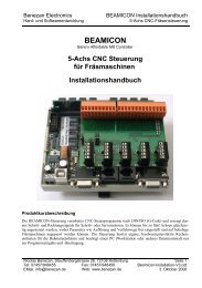
<strong>Benezan</strong> <strong>Electronics</strong>Hard- and Software Development<strong>Triple</strong> <strong>BEAST</strong> Stepper DriverInstallation Manualcan connect a 6 wire motor half or full winding, an 8 wire motor in series or parallel connection. With series orparallel connection polarity of the windings matter. But the <strong>Triple</strong>Beast will not be damaged by a false windingconnection. In the case of a misconnection the fault LED of the axis will light up.3.5 Configuration and Status DisplayOn the left side the <strong>Triple</strong>Beast has so called „piano switches“ to set operating mode and phase current of themotors. The switch is open (0=OFF) in the neutral position (right in the picture) and closed (1=ON) whenpressed down (left in the picture).No. Beschreibung1 0 = standard, 1 = remote configuration (not supported)2 Waveform: 0 = pure sine, 1 = sine wave with overtone3 Phase current selection for axis #1 (X)4 (see table below)5 Phase current selection for axis #2 (Y)6 (see table below)7 Phase current selection for axis #3 (Z)8 (see table below)9 Microstep resolution: 0 = 1/10 (2000/rev) 1 = 1/5 (1000/rev)10 Motor phase current, coarse range selection: 0 = 1.4..3.2A, 1 = 2.5..5ASwitch no. 10 is used to coarsly select the motor phase current range for all axes. Thismeans that the minimum and maximum current can't be used at the same time. All motorsmust be either between 1.4 and 3.2 or between 2.5 and 5A. The fine adjustment can beselected with switches no. 3 to 8 seperately for each motor.Switch no. 2 selects the current waveform. Some motors have a slightly distortedwaveform instead a pure sine wave. Closing the switch adds a small overtone component tothe current which reduces vibrations for those motors. It's hard to tell which setting isoptimum for a given motor. The easiest way to find out is by trying out.You can choose between two different microstep resolutions with switch no. 9. OFFmeans 1/10 microstep or 2000 steps per rovolution for a standard motor. ON means1/5 microstep or 1000 steps per revolution.Stepper motor drivers from other manufacturers often have a bewildering numberof resolution settings. Their idea is to select the highest possible resolution that doesn'trequire step rates above the frequency limit of the controller. In most cases, highresolution is not really necessary for accuracy but helps keeping noise and vibrationslow. With the <strong>Triple</strong> Beast things are completely different. Even at the lowestresolution of 1/5 microstep there are no noise or viration of distinct steps at all. Thedrive always outputs a smooth sine wave instead of a staircase function. For mostapplications 1/10 microstep resolution is the optimum and allows speeds up to1350rpm at 45kHz pulse frequency. Higher resolutions would result in no betteraccuracy because of the step tolerance of the motor (usually 5% of one full step). The1/5 microstep setting is for controller software which is limited to around 20kHz pulsefrequency.Status DisplayBereich■□ = 1Bereich□■ = 0The status of the drive is displayed by five LEDs on the left side (see picture above). The meaning ofcombinations of different colors is listed in the following table:□■□■□■■□■□□■■□■□2,5A□■□■ 1,4A3,2A□■■□ 2,0A4,2A■□□■ 2,5A5,0A■□■□ 3,2ANicolas <strong>Benezan</strong>, Stauffenbergstr. 26, 72108 RottenburgTel: +49 7457 / 946365 0 benezan-electronics.deSeite 5<strong>Triple</strong>Beast+BOB-Manual.odt2012-02-01
<strong>Benezan</strong> <strong>Electronics</strong>Hard- and Software Development<strong>Triple</strong> <strong>BEAST</strong> Stepper DriverInstallation ManualLEDs Beschriftung Beschreibung (green) Running Motors running at full current (yellow) Standby Motors standing still at reduced current (red blinking) Fault Axis .. A single LED blinking indicates a short circuit, overload or false wiringat the corresponding motor. The remaining motors are still active asshown by the yellow or green LED. (red blinking) Fault Axis .. If all red LEDs are blinking simultanously the power stage is overheatedand all motors are deenergized. (yellow redalternately)Fault Axis .. If all red and yellow LEDs are blinking alternatively the power stage hasbeen switched off due to overvoltage. The cause could be either thesupply or too much back EMF at decelleration.The LEDs on the top face diplay the status of the PC interface board.LEDs Beschriftung Beschreibung 1 (green) Power Power supply ok 2 (green) Charge Pump Watchdog (charge pump) aktive 3 (red) Drive Fault Fault at one or more power stages 4 (red) E-Stop Emergency stop switch open or disconnected 5 (yellow) Relay 1 Relay 1 on (spindle motor) 6 (yellow) Relay 2 Relay 2 on (coolant or vacuum)3.6 PC-AnschlussFor the connection of the breakout board to the PC or controller please use a parallel printer cable with 25 pinSUBD connectors (male/female). Each pin should be connected one by one, especially the ground pins (#18 to25). The maximum recommended length is 3m.The pion assignment is compatible to Mach3, EMC or WinPCNC. If you use different controller software itmight be necessary to use an adaptor or patch box to change the pin assignment. Please note that <strong>Benezan</strong><strong>Electronics</strong> is not able to know and support any software available. We only guarantee full functionality withMach3.The pinout is shown in the following table:Nicolas <strong>Benezan</strong>, Stauffenbergstr. 26, 72108 RottenburgTel: +49 7457 / 946365 0 benezan-electronics.deSeite 6<strong>Triple</strong>Beast+BOB-Manual.odt2012-02-01
<strong>Benezan</strong> <strong>Electronics</strong>Hard- and Software Development<strong>Triple</strong> <strong>BEAST</strong> Stepper DriverInstallation ManualNr. Beschreibung Nr. Beschreibung1 Relay #1 (spindle) or PWM 14 Relay #2 (coolant)2 Direction X 15 Home or limit switch 4 th axis3 Step pulse X 16 Charge pump or current hi/low4 Direction Y 17 PWM or current hi/low5 Step pulse Y 186 Direction Z 197 Step pulse Z 208 Direction 4 th axis 219 Step pulse 4 th axis 22Signal ground10 Home or limit switch Z 2311 Emergency stop 2412 Home or limit switch Y 2513 Home or limit switch XSome pins have more than one possible assignment to support different software or different machineconfigurations. The selection is made with the jumpers next to the SUBD-connector. The header pins for thejumpers are numbered from 1 on the right side to 11 on the left. A jumper always connects to neighbouring pins.(2-1) A Jumper on pins 1 and 2disables the watchdog, this means allfunctions are always enabled when thepins are connected, as if the chargepump signal was always present. This isrequired for software that does notsupport a charge pump or toggle signal.The drawback is that undefined orrandom states of the port pins duringbooting can accidentally cause unwantedswitching of the relays or movement ofthe axes which could be dangerous. Ifthe pins 1-2 are open the watchdog isactive and prevents unwantedmovements and switching.(9..3) These pins are used for theconfiguration of the PWM, currentreduction and relay signals. Choose oneof the following configuration:• 8-7, 6-5, 4-3: Relay #1 on ifPWM>10%, current reductionat pin 17, PWM at pin 1,watchdog at pin 16• 9-8, 7-6, 5-4: Relay #1 at pin 1, PWM at pin 17, current reduction at pin 16, no watchdog (jumper 1-2has to be closed)• 7-6, 5-4: Relay #1 at pin 1, PWM at pin 17, no current reduction, watchdog at pin 16• 8-7, 5-4: Relay #1 at pin 1, no PWM, current reduction at pin 17, watchdog at pin 16• 2-9 (jumper wire), 4-5, 6-7: special configuration for USB-CNC V5A, also see page 11(16..12) Theese jumpers are used to select the supply voltage for the home or limit switches and toenable/disable the 4 th axis (see below)3.7 Home or limit switchesUp to 4 inputs for home or limit switches are supported. If a switch for the 4th axis is not needed you canalternatively use this input for a tool length measurement switch.Nicolas <strong>Benezan</strong>, Stauffenbergstr. 26, 72108 RottenburgTel: +49 7457 / 946365 0 benezan-electronics.deSeite 7<strong>Triple</strong>Beast+BOB-Manual.odt2012-02-01
<strong>Benezan</strong> <strong>Electronics</strong>Hard- and Software Development<strong>Triple</strong> <strong>BEAST</strong> Stepper DriverInstallation ManualIt is possible to use mechanical switches or electronic proximity sensors. For mechanical switches, both NC orNO types can be used. You can invert the signal in the software if necessary. The jumper for the switch supplyshould be set to 13-14 and the supply voltage of the board can be any DC voltage from 15 to 80V. Connect eachswitch to terminals 1 and 2, 3 and 4, 5 and 6 or 7 and 8.If you use electronic sensors make sure to set jumper 12-13 for 24V sensor supply. As the board doesn't havea separate 24V voltage regulator it is required to use a 24V supply for the board. The motor supply can't be usedin this case if it's higher than 24V. Sensors should be connected as follows: positive supply (brown wire) toterminal 1, 3, 5, or 7, negative supply (blue wire) to ground (at the 24V power supply), sensor signal (black wire)to terminal 2, 4, 6, or 8.All inputs have an RC low pass filter and are protected against electromagnetic interference and voltagespikes up to 80V. Normally, shielded cables are not necessary for the switch inputs as long as EMC guidelinesfor motor cables and other high power devices (VFDs) are followed.3.8 Auxilliary functionsAt terminal X2 you can connect an emergency stop button and optionally a holding brake for a vertical axis andthe nominal speed input of a variable frequency drive (VFD).Emergency stopThe breakout board offers the following features to stop movement or program execution in the case ofemergeny or hardware problems:1. At the terminals X2.5 and X2.6 an emergency stop switch („mushrom button“) has to be connected. Ifthe circuit is open relays #1 and #2 are forced off. The E-stop condition is signaled with LED #4 (red,see picture on page 6) and pin 11 of the LPT port goes low so that the software can stop programexecution.2. If one or more of the power stages (axes 1 to 3) or an external drive (4th axis if present) signals a faultcondition, LED #3 („drive fault“, red) lights up and pin 11 of the LPT port also goes low. You can lookat the status leds for each axis on the left side to see which axis caused the fault.3. In the case of an emergency stop or drive fault the relay for the holding brake opens so that the brake (ifpresent) engages.4. If the watchdog is active (jumper 1-2 open) relay outputs and step pulse signals are only enabled ifthere's a valid charge pump (toggle) signal.Please be aware that depending on the risk of injury it may necessary to install additional security devices. Forexample, it might be necessary to cut power to the motor drivers with a second E-stop circuit.Analogue output (VFD speed signal)Th <strong>Triple</strong>Beast has an analogue 0..10V output to control the speed of a VFD (variable frequency drive). Theoutput signal is proportional to the duty cycle of the PWM (pulse width modulation) input signal at pin 1 or 17 ofthe LPT port. 0% duty results in 0V output, 20% in 2V and so on until 100% for 10V output.The base frequency of the PWM signal should be 45Hz or higher. This allows a resolution of 10 bits at 45kHzkernel speed with Mach3, for example. If all of the features 4th axis, PWM, relays and current reduction have tobe used at the same time it's likely to run out of pins at the LPT port. For this reason it is possible to use the samepin for PWM and relay #1. If jumper 3-4 is closed relay #1 switches on whenever the PWM signal has 10% dutyor more. Therefore the minimum pulse width should be set to 10% for this case.Brake for vertical axisWhen low friction ball screws are used together with heavy weight or high pitch at vertical axes it may berequired to use an electromechanical holding brake to avoid uncontrolled descending when power is off.Especially servo motors have nearly no detent torque and are sensitive to this phenomenon. For this reason,motors are available with brakes that are normally closed and open if 24V power is applied.The <strong>Triple</strong>Beast has a relay output for such holding brakes. The output is active (brake open) whenever the<strong>Triple</strong>Beast is powered and there is no e-stop or drive fault condition. The output has a free wheeling diode andcan be used to directly switch inductive loads up to 5A. The relay is directly connected to the supply voltage ofNicolas <strong>Benezan</strong>, Stauffenbergstr. 26, 72108 RottenburgTel: +49 7457 / 946365 0 benezan-electronics.deSeite 8<strong>Triple</strong>Beast+BOB-Manual.odt2012-02-01
<strong>Benezan</strong> <strong>Electronics</strong>Hard- and Software Development<strong>Triple</strong> <strong>BEAST</strong> Stepper DriverInstallation Manualthe breakout board. This means, you have to use a 24V supply if you have a 24V brake. If the brake ispneumatic, hydraulic or has a higher violtage you have to use an external relay or solenoid.4th Axis ExtensionA driver for a 4th axis can be connected to the RJ45 socket at the top. If you use a <strong>BEAST</strong> stepper driver orUHU servo drive from <strong>Benezan</strong> Electgronics you can simply use a standard network patch cable. Of course youcan also use drivers from other manufacturers. For this case the following pinout applies:No. Beschreibung1 current reduction2 signal ground3 step pulse4 +5V5 direction6 +5V7 status (0=ok, 1=error)8 signal groundIf the driver has no status output pin 7 and 8 have to be connected or jumper no. 15-16 must be closed. If you usea <strong>BEAST</strong> or UHU drive please leave jumper 15-16 open.4 Commissioning and troubleshootingIf you set the controller into operation for the first time please check the following items before.• Are all terminals properly aligned in their sockets• Is the supply conected to terminal X1 with the correct polarity?• If the supply voltage is more than 28V you have to select 12V as supply for the limit switches (jumper13-14 closed, 12 open)• Is the emergency stop switch connected? A jumper wire is only allowed for testing purposes if (andonly if) there's no risk of injury.• Please double check if all jumpoer settings match the pinout of the controller software.If theese conditions are met you can connect the <strong>Triple</strong>Beast to the PC, switch on the power supply and start upthe controller software. After startup the state of the LED lights should be as follows (some software requiresclicking the reset button):• Both green LEDs (power and charge pump) have to be lit,• both red LEDs (drive fault and E-stop) must be off,• the yellow LEDs (relay 1 and 2) must be off.If this is not the case please read the chapter „troubleshooting“ below. If everything is OK you can proceed withtesting the motors, relays and switches.Nicolas <strong>Benezan</strong>, Stauffenbergstr. 26, 72108 RottenburgTel: +49 7457 / 946365 0 benezan-electronics.deSeite 9<strong>Triple</strong>Beast+BOB-Manual.odt2012-02-01
<strong>Benezan</strong> <strong>Electronics</strong>Hard- and Software Development<strong>Triple</strong> <strong>BEAST</strong> Stepper DriverInstallation ManualTroubleshootingThe following table lists the most comon errors and possible causes.No. Symptom Ursache1 LED „Power“ (green) not lit Power supply not connected or polarity wrong, check terminal X1and V)2 LED „Charge Pump“ (green) notlit3 LED „Drive Fault“ (red, on top)is on, LEDs „Fault Axis 1-3“ (redat the left side) is off4 LED „Drive Fault“ (red, on top)is on, LEDs „Fault Axis 1-3“ (redat the left side) blinking5 LED „E-Stop“ (red) is on, LED„Standby“ (yellow) blinkingThere must be a square wave signal of at least 5kHz at pin 16 ofthe LPT port. If your controller software doesn't support this, closejumper no. 1-2without 4th axis: jumper 15-16 is missingwith 4th axis: driver not (properly) connected or not poweredOne or more motor drivers have a fault condition (overheated orshorted, see page 6)E-stop switch not connected or activated (X2 pin 5-6 open)6 Relays don't work a) yellow LEDs on but relays not: see case no. 5b) yellow LEDs off: jumpers or software configured incorrectly7 Motors don't turn a) green LED „ChargePump“ off: see case no. 2b) step and direction signals swapped? (LPT pins 2,4,6,8 = dir,pins 3,5,7,9 = step)8 VFD drive speed fluctuations PWM base frequency too low (minimum 45Hz)9 E-stop signal doesn't work (LPTpin 11)10 Motors move one step when E-stop switchespin 11 must be set as „active low“, LEDs „Drive Fault“ (see case3) and „E-Stop“ (see case 4) must be inactive.polarity of step signal wrong (toggle „active low“)Nicolas <strong>Benezan</strong>, Stauffenbergstr. 26, 72108 RottenburgTel: +49 7457 / 946365 0 benezan-electronics.deSeite 10<strong>Triple</strong>Beast+BOB-Manual.odt2012-02-01
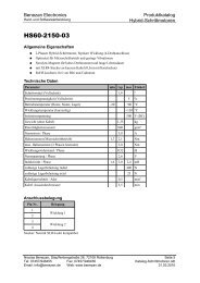
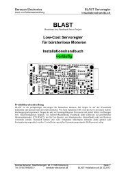
<strong>Benezan</strong> <strong>Electronics</strong>Hard- and Software Development<strong>Triple</strong> <strong>BEAST</strong> Stepper DriverInstallation Manual5 Software configurationMach3 config exampleIn the pictures on the left you can seethe input and output assignments forthe standard jumper setting (pins 3-4,5-6 and 7-8 closed). Additionalsettings:• XHome pin 13• YHome pin 12• ZHome pin 10• AHome or probe switch pin15• RelayControl:M3 and M4 → Output#1M7 and M8 → Output#2• Motor Control:√ Use Spindle Motor Output√ PWM ControlPWM Base Freq. = 45Minimum PWM = 10%In Mach3 the pins for step and dir outputs can be swapped arbitrarily. Therefore you can also assign the outputfor the 4th axis to the logical X, Y or Z axis. This is useful if you need a bigger motor (and an external, biggerdriver) for one of those axes.Configuration for USB-CNCThe <strong>Triple</strong> Beast can also be cennected directly to the USB-CNC controller V5A. For the watchdog to workproperly the jumper „WDCF“ on the USB-CNC board has to be set like this: upper jumper to the right, lowerjumper to the right. The jumper „Volt-PWM“ must also be set to the right.At the <strong>Triple</strong>Beast, jumper pin no. 9 must be connected to pin no. 2 with a jumper wire. Jumpers 4-5 and 6-7have to be closed, pins 1,3 and 8 have to be open. The remaining jumpers 12-16 can be set depending on theapplicationn as described on page 8..9.Other Control SoftwareThe <strong>Triple</strong>Beast also works well with NCdrive, EMC², WinPCNC and other CNC software. It would be out ofthe scope of this manual to cover any possible configuration. If you have questions abaout the setup of yoursoftware or compatibility issues please contact your dealer or <strong>Benezan</strong> <strong>Electronics</strong>.Nicolas <strong>Benezan</strong>, Stauffenbergstr. 26, 72108 RottenburgTel: +49 7457 / 946365 0 benezan-electronics.deSeite 11<strong>Triple</strong>Beast+BOB-Manual.odt2012-02-01
<strong>Benezan</strong> <strong>Electronics</strong>Hard- and Software Development<strong>Triple</strong> <strong>BEAST</strong> Stepper DriverInstallation Manual6 Specifications6.1 Absolute Maximum RatingsThe following operating parameters have to be kept within their limits or otherwise irreversible damage couldoccur:Parameter min. max. UnitSupply voltage -0,5 +63 VdcStorage temperature -40 +85 °Cambient temperature -20 +70 °CVoltage at LPT port (SUBD25), any pin to ground -0,5 +5,5 VVoltage at switch inputs -5 +63 VVoltage at relay contacts (X4) 30 Vdc250 Vaccurrent per relay contact pair (X4) 8 Aeffcurrent at brake relay output (X2) 5 Acurrent at analoge output 0..10V 20 mA6.2 Operating conditionsParameter min. max. UnitSupply voltage +24 55 Vdcquiescent current consumption (no load) 80 mA12V output max. load 300 mA5V output ma. load 200 mAambient temperature (operating) 0 +50 °Clow level input (LPT port) -0,5 +0,8 Vhigh level input (LPT port) 2,5 +5,5 Vcurrent at input @0..5V (LPT port) 0 1 mAstep pulse width 2 µssetup time direction valid to step 1 2 µshold time direction valid after step 2 µslow level output 0,8 Vhigh level output 3 Vstep frequency 0 200 kHzwatchdog (charge pump) frequency 5 100 kHztime delay step to current reduction 0,5 0,7 sovertemperature threshold 70 85 °Cmotor current accuracy -10 +10 %wire gauge supply voltage 0,5 2,5 mm²wire gauge motor outputs 0,22 1 mm²microsteps per full step 5 10 -microsteps per revolution for standard motor 2 1000 2000 -1 step is executed at rising edge, e.g. at transition from low to high level2 standard motor: 1,8° per full step, 200 full steps per revolutionNicolas <strong>Benezan</strong>, Stauffenbergstr. 26, 72108 RottenburgTel: +49 7457 / 946365 0 benezan-electronics.deSeite 12<strong>Triple</strong>Beast+BOB-Manual.odt2012-02-01