Series 100-200-586 - Düsen-Schlick GmbH
Series 100-200-586 - Düsen-Schlick GmbH
Series 100-200-586 - Düsen-Schlick GmbH
- No tags were found...

You also want an ePaper? Increase the reach of your titles
YUMPU automatically turns print PDFs into web optimized ePapers that Google loves.
www.duesen-schlick.de<strong>Schlick</strong><strong>Series</strong> <strong>100</strong>-<strong>200</strong> and<strong>Series</strong> <strong>586</strong>Hollow-Cone NozzlesApplications:- Air conditioning- Combustion- De-icing- Direct lubrication- Fabric moisturising- Gas conditioning- Gas cooling- Granulating equipment- Grease atomising- Humidifying- Mixing- Process engineering- Pulp moisturising- Spray drying- Steam condensation- Superheated steam cooling- Tobacco moisturising- Water recooling- Water treatmentTechnical information 5/01
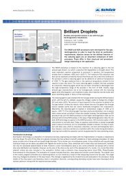
www.duesen-schlick.de<strong>Schlick</strong> hollow-cone nozzles• Hollow-cone nozzles atomise liquids under pressure intofinest droplets having a large specific surface.• The liquid is fed to the nozzle under pressure and entersthe swirl chamber through tangential slits.• In the swirl chamber the energy in the pressurised liquidis converted into rotational energy.• A centrifugal film of rotating liquid forms a hollow cone.After overcoming surface tension, the cone disperses intoa myriad of fine droplets.• The nozzles are available with 0.1 mm to 60 mm diameterorifices.• Nozzles from 0.1 to 0.5 mm diameter are fitted with astrainer to protect against clogging.• Spray angles of 15°, 30°, 45°, 60°, 90° and 120° are possible.• Nozzles with 0.1 to 0.3 diameter orifices are only availablewith standard spray angles.• Standard spray angles are approx.60° for 0.1 to 0.5 mm diameter orifices70° for 0.5 to 1.6 mm diameter orifices78° for 1.61 to 2.5 mm diameter orifices80 to 85° from 21 mm upwards• The nozzle is given a smaller or larger orifice than thosequoted in the table for smaller or larger spray angles. Therespective flow rates correspond to the standard orifice.The overall height of the nozzle may change.• Δp = 3 bar has been chosen as the test and rated pressure(generally available from the water mains).• The quality of the atomised spray and the dropletspectrum are related to the diameter of the orifice,pressure, spray angle, density, viscosity, and surfacetension.• Minimum atomising pressure0.1 – 0.5 mm diameter: Δp = 3 – 6 bar0.5 – 1.6 mm diameter: Δp = 0.5 bar< 1.6 mm diameter: Δp = 0.1 – 0.5 bar• For droplet size the following applies:For the same orifice,higher pressure → smaller dropletslower pressure → larger dropletsFor the same pressure,larger orifice → larger dropletssmaller orifice → smaller dropletsd T ~ diameterFor same pressure and same orifice,larger spray angle → smaller dropletssmaller spray angle → larger dropletsd T ~1spray angle• Liquids with a higher viscosity and surface tension haveto be tested, as atomisation could be coarser.Other hollow-cone nozzles:Models 118, 202, 432:Models 121, 123:Models 400, 401:for abrasive liquids and for spray dryingfor low flow rates and fine atomisingfor liquids with a tendency to clogNozzle designsModel <strong>100</strong> – Hollow-cone nozzleFig. 05001Model <strong>200</strong> – Hollow-cone nozzleFig. 050022
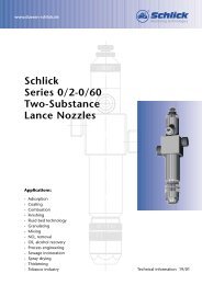
www.duesen-schlick.deAssembliesModel <strong>100</strong> Form 7-1 – Hollow-cone nozzlePneumatically controlled by control air. A needle closes theoutlet abruptly when the control air is shut off. Especiallysuitable for etching, marking, cyclic spraying and above allfor liquids under pressure where drips are to be avoided.Fig. 05003Model <strong>100</strong> Form 8 – Hollow-cone spray nozzleWith solenoid valve.Standard design: 220 V, 50 Hz, <strong>100</strong> % ED.Ambient temperature:max. 55 °C, enclosure protection IP 65.Cycling frequency: limited only by the changeover time.Fig. 05004Model 103 – Hollow-cone nozzleShort formFig. 05005Model 104 – Hollow-cone nozzleFor right-angled installationFig. 05006Model <strong>586</strong> – Hollow-cone nozzleFor cooling superheated steamMoving centrifugal core (non-return valve function)Dimensions and flow rates on requestStandard orifices in mm:Size 1, G 1 / 4 : 1.1 - 1.6 - 2.3 - 2.8 - 3.2 - 3.9 - 4.2 - 4.5 - 4.8Size 2, G 3 / 8 : 5.0 - 5.5 - 6.0Size 3, G 1 / 2 : 7.0 - 8.0Size 4, G 3 / 4 : 10.0 - 11.0Fig. 05007Materials- Brass- Acid resistant stainless steel- Heat resistant stainless steel- Titanium- Tantalum- HASTELLOY- INCONEL- Platinum-Iridium- PVC- PTFE- PP- RCH <strong>100</strong>0- PVDFCustom products from othermaterials available on request3
➝www.duesen-schlick.deDimensionsModel <strong>100</strong> standard design (length is longer for spray angles < 60°)Size 1 2 3 4 5 6 7 8 9 10Connector G ISO 228 1 /8 1 /4 3 /8 1 /2 3 /4 1 1 1 / 4 1 1 / 2 2 3Thread length L 8 9 11 14 16 19 20 21 24 30Total height H 26 32 40 50 63 80 90 <strong>100</strong> 110 160Spanner size SW 17 20 24 27 36 46 55 65 80 120Weight of brass ca. kg 0.03 0.05 0.08 0.12 0.28 0.70 0.88 1.40 2.40 6.00Model <strong>200</strong> with hexagonal fittingSize 1 2 3 4 5 6Connector G ISO 228 1 /8 1 /4 3 /8 1 /2 3 /4 1Thread length L 8 9 11 14 16 19Total height H 31 38 47 58 70 95Spanner size SW 17 20 24 27 36 46Weight of brass ca. kg 0.04 0.08 0.12 0.22 0.31 0.90Model 103 short designOrifices and flow rates are table sorted to size and not to connection threadSize 1 2 3 4 5 6 7Connector G ISO 228 3 /8 1 /2 3 /4 1 1 1 / 4 1 1 / 2 2Thread length L 11 14 16 19 20 21 24Total height H 18 21 28 36 46 60 68Spanner size SW 20 24 32 36 46 55 65Model 104 with right-angled connectionSize 1 2 3 4 5 6 7Connector G ISO 228 1 /8 1 /4 3 /8 1 /2 3 /4 1 1 1 / 4Thread length L 8 9 11 14 16 19 20Total height H 30 30 40 50 60 75 85Length A 30 30 40 50 60 70 80Cone diametermm0<strong>200</strong>400600800<strong>100</strong>01<strong>200</strong>140016001800<strong>200</strong>02<strong>200</strong>240026002800Size 3: orifice dia. 5 mm78°Model <strong>100</strong>0.5 1 2 478°Δ p barSize 6: orifice dia. 15 mmmm Ømm Ø0.5 Δ p bar–––––––––––––––––––––––➝–––––––––––––––––––––––––––––––➝1<strong>200</strong> <strong>200</strong>0 1<strong>200</strong> <strong>200</strong>0 28001600 24001600 2400 3<strong>200</strong>1-44
www.duesen-schlick.dePerformance specificationPerformance data of hollow-cone nozzlesModel<strong>100</strong>/<strong>200</strong>Nozzleorifice ØFlow rate in l/min atsize in mm 0.25 bar 0.5 bar 1 bar 2 bar 3 bar 4 bar 6 bar 8 bar 10 barNozzlesprayangle in °1. G 1 / 8 0.3 0.035 0.040 0.050 0.057 0.064 600.4 0.062 0.072 0.088 0.<strong>100</strong> 0.113 600.5 0.080 0.097 0.111 0.138 0.159 0.178 630.8 0.204 0.250 0.288 0.354 0.408 0.457 681.1 0.270 0.380 0.470 0.540 0.660 0.770 0.860 701.6 0.41 0.58 0.81 1.00 1.16 1.43 1.64 1.83 722.3 0.60 0.84 1.19 1.68 2.06 2.38 2.92 3.37 3.76 752.8 0.88 1.24 1.76 2.48 3.05 3.52 4.32 4.98 5.57 782. G 1 / 4 3.2 1.15 1.63 2.30 3.26 4.00 4.62 5.65 6.52 7.30 783.6 1.45 2.06 2.92 4.12 5.05 5.83 7.15 8.25 9.20 783.9 1.70 2.41 3.40 4.80 5.90 6.82 8.35 9.63 10.75 784.2 1.98 2.82 3.98 5.63 6.90 7.95 9.75 11.30 12.60 784.5 2.28 3.23 4.55 6.45 7.90 9.10 11.20 12.90 14.40 784.8 2.60 3.68 5.20 7.35 9.00 10.40 12.75 14.70 16.50 783. G 3 / 8 5.0 2.80 4.00 5.60 7.95 9.75 11.13 13.80 15.90 17.80 785.5 3.40 4.82 6.80 9.65 11.80 13.60 16.70 19.25 21.50 786.0 4.05 5.70 8.10 11.40 14.00 16.20 19.80 22.80 25.60 784. G 1 / 2 7.0 5.50 7.80 11.00 15.60 19.10 22.00 27.00 31.20 34.80 788.0 7.20 10.20 14.40 20.40 25.00 28.80 35.40 40.80 45.70 785. G 3 / 4 10.0 11.30 15.90 22.50 31.80 39.00 45.00 55.20 63.70 71.20 7811.0 13.60 19.20 27.20 38.40 47.00 54.50 66.50 77.00 86.00 786. G1 13.0 19.00 27.00 38.00 54.00 66.00 76.00 93.00 108.00 120.00 7815.0 25.00 36.00 51.00 72.00 88.00 102.00 124.00 144.00 161.00 787. G1 1 / 4 18.0 36.00 51.00 73.00 103.00 126.00 145.00 178.00 206.00 230.00 7921.0 50.00 70.00 99.00 140.00 172.00 197.00 244.00 281.00 314.00 808. G1 1 / 2 23.0 60.00 84.00 119.00 168.00 206.00 238.00 292.00 337.00 376.00 8125.0 70.00 <strong>100</strong>.00 140.00 198.00 243.00 280.00 344.00 397.00 445.00 829. G2 30.0 102.00 143.00 203.00 287.00 352.00 406.00 497.00 575.00 642.00 8336.0 145.00 206.00 292.00 412.00 505.00 583.00 650.00 715.00 825.00 8410. G3 50.0 280.00 400.00 560.00 795.00 975.00 1113.00 1380.00 1590.00 1780.00 8560.0 405.00 570.00 810.00 1140.00 1400.00 1620.00 1980.00 2280.00 2560.00 85• Flow referred to water at 16 °C – see conversion table for liquids of other densities.• Orifice diameters are given in 1 / 10 mm on the individual nozzles.• For technical reasons, nozzles with a spray angle that deviates from the standard are provided with a smaller or largeroutlet orifice. The individual flow rates, however, correspond to the standard orifice.Conversion factor for density1.61.41.21.00.80.6➝ Factor0.40.<strong>200</strong> 0.5 1.0 1.5 2.0 2.5 3.0 3.5➝ Density (kg/dm 3 )• Flow rates differ for liquids of densities deviating from that of water.• Use the conversion factors on the left to determine flow rates.• To convert the flow rate, simply multiply the value referring to water from thetable above by the respective conversion factor.• The influence of viscosity cannot be calculated. The flow rate must be determinedexperimentally for values differing largely from water.5
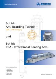
www.duesen-schlick.deDroplet SizeHollow-cone spray nozzlesMean volume droplet size in microns260240➝ Mean volume droplet size in microns220<strong>200</strong>180160140120<strong>100</strong>806040<strong>200</strong>080 bar50 bar30 bar20 bar10 bar6 bar3 bar1 bar0.1 0.2 0.3 0.4 0.5 0.6 0.7 0.8 0.9 1 1.1 1.2 1.3 1.4 1.5 1.6 1.7 1.8 1.9 2➝ Orifice diameter in mm for a standard spray angleLaser measurement of a Model <strong>100</strong> spray angle0.7 mm orifice with standard spray pattern at a liquiddifferential pressure of 8 bar6
www.duesen-schlick.deCustom versionsModel <strong>200</strong> S28 – Hollow-cone nozzleWith strainer attachmentFig. 05008Model <strong>200</strong> S8 – Hollow-cone nozzleWith extended thread fitting for installation in wallsFig. 05009Model 103 S14 – Hollow-cone nozzleFor insertion pipes, with slots to screw in the nozzleFig. 05010Custom designs/specialitiesModel <strong>100</strong> Form 5 S31 – Hollow-cone nozzleWith heating system and flanged mountingFig. 05011Model <strong>100</strong> Form 7-1 – Hollow-cone nozzleWith pneumatic OPEN/CLOSE control and diary fittingFig. 050127
www.duesen-schlick.deService spectrumPilot test laboratoryBefore any new spray nozzles are usedwe subject them to comprehensivetrials in our own test laboratory – if needbe to your operational parameters.During these tests, we preciselydetermine droplet size, velocities andflow densities with our modern DUALPDA laser-measuring equipment.Test nozzles<strong>Schlick</strong> spray nozzles are worldrenowned for highest precision. Wecan offer you the best and mostlasting solution to your requirements.And, if you want, we can supplyyou with test nozzles in advance –just contact us.EngineeringTake advantage of our comprehensiveexpertise – from design to installation– the conception of new products orthe optimisation of existing plant. Wewould be glad to help you improvethe success of your operation.Repair serviceAs well as competent advice and itsinception, you can profit from anefficient after-sales service thatguarantees long-term supply of allproducts. We carry out both repairand conversion of <strong>Schlick</strong> spraynozzles, and in emergency, we cansupply spare parts quickly and reliably.Onsite serviceIf required we will investigate anddevelop an optimal solution to suitindividual requirements onsite. Wewill advise you and give you supportduring installation and initial start-upof the plant. A further plus is thehelp available from our worldwidetechnical field service network.Custom productsAs one of the leading spray nozzlemanufacturers in Europe, we canoffer both high quality standardsolutions and are in the position ofdeveloping customised products forindividual tasks as fast as possible,even for small production runs.Documentation to thecustomer’s requirementsReliability and quality are the basisfor successful cooperation with ourinternational customers. This appliesboth to our products and to ourservice. If you wish, we will supplyyou with all necessary documentationsuch as technical handbooks for thenozzles (drawings, flow diagrams,installation and operating instructions)together with factory and materialspecifications.All specifications are subject to change (flowrates/dimensions).The performance/flow rate specifications quotedare descriptive or product identities and can varyby up to ±5 percent on delivery.Certified byto DIN EN ISO9001: <strong>200</strong>0Düsen-<strong>Schlick</strong> <strong>GmbH</strong>Hutstraße 496253 UntersiemauGermanyTel. +49 95 65 94 81 0Fax +49 95 65 28 70info@duesen-schlick.dewww.duesen-schlick.dewww.duesen-schlick.comd·LH·02.03